EP1433862A1 - Magnesium base composite material - Google Patents
Magnesium base composite material Download PDFInfo
- Publication number
- EP1433862A1 EP1433862A1 EP02763033A EP02763033A EP1433862A1 EP 1433862 A1 EP1433862 A1 EP 1433862A1 EP 02763033 A EP02763033 A EP 02763033A EP 02763033 A EP02763033 A EP 02763033A EP 1433862 A1 EP1433862 A1 EP 1433862A1
- Authority
- EP
- European Patent Office
- Prior art keywords
- magnesium
- composite material
- base composite
- less
- powder
- Prior art date
- Legal status (The legal status is an assumption and is not a legal conclusion. Google has not performed a legal analysis and makes no representation as to the accuracy of the status listed.)
- Withdrawn
Links
Images


Classifications
-
- C—CHEMISTRY; METALLURGY
- C22—METALLURGY; FERROUS OR NON-FERROUS ALLOYS; TREATMENT OF ALLOYS OR NON-FERROUS METALS
- C22C—ALLOYS
- C22C32/00—Non-ferrous alloys containing at least 5% by weight but less than 50% by weight of oxides, carbides, borides, nitrides, silicides or other metal compounds, e.g. oxynitrides, sulfides, whether added as such or formed in situ
- C22C32/0047—Non-ferrous alloys containing at least 5% by weight but less than 50% by weight of oxides, carbides, borides, nitrides, silicides or other metal compounds, e.g. oxynitrides, sulfides, whether added as such or formed in situ with carbides, nitrides, borides or silicides as the main non-metallic constituents
- C22C32/0078—Non-ferrous alloys containing at least 5% by weight but less than 50% by weight of oxides, carbides, borides, nitrides, silicides or other metal compounds, e.g. oxynitrides, sulfides, whether added as such or formed in situ with carbides, nitrides, borides or silicides as the main non-metallic constituents only silicides
-
- C—CHEMISTRY; METALLURGY
- C01—INORGANIC CHEMISTRY
- C01B—NON-METALLIC ELEMENTS; COMPOUNDS THEREOF; METALLOIDS OR COMPOUNDS THEREOF NOT COVERED BY SUBCLASS C01C
- C01B33/00—Silicon; Compounds thereof
- C01B33/06—Metal silicides
-
- C—CHEMISTRY; METALLURGY
- C04—CEMENTS; CONCRETE; ARTIFICIAL STONE; CERAMICS; REFRACTORIES
- C04B—LIME, MAGNESIA; SLAG; CEMENTS; COMPOSITIONS THEREOF, e.g. MORTARS, CONCRETE OR LIKE BUILDING MATERIALS; ARTIFICIAL STONE; CERAMICS; REFRACTORIES; TREATMENT OF NATURAL STONE
- C04B35/00—Shaped ceramic products characterised by their composition; Ceramics compositions; Processing powders of inorganic compounds preparatory to the manufacturing of ceramic products
- C04B35/515—Shaped ceramic products characterised by their composition; Ceramics compositions; Processing powders of inorganic compounds preparatory to the manufacturing of ceramic products based on non-oxide ceramics
- C04B35/58—Shaped ceramic products characterised by their composition; Ceramics compositions; Processing powders of inorganic compounds preparatory to the manufacturing of ceramic products based on non-oxide ceramics based on borides, nitrides, i.e. nitrides, oxynitrides, carbonitrides or oxycarbonitrides or silicides
- C04B35/58085—Shaped ceramic products characterised by their composition; Ceramics compositions; Processing powders of inorganic compounds preparatory to the manufacturing of ceramic products based on non-oxide ceramics based on borides, nitrides, i.e. nitrides, oxynitrides, carbonitrides or oxycarbonitrides or silicides based on silicides
-
- C—CHEMISTRY; METALLURGY
- C22—METALLURGY; FERROUS OR NON-FERROUS ALLOYS; TREATMENT OF ALLOYS OR NON-FERROUS METALS
- C22C—ALLOYS
- C22C29/00—Alloys based on carbides, oxides, nitrides, borides, or silicides, e.g. cermets, or other metal compounds, e.g. oxynitrides, sulfides
- C22C29/18—Alloys based on carbides, oxides, nitrides, borides, or silicides, e.g. cermets, or other metal compounds, e.g. oxynitrides, sulfides based on silicides
-
- B—PERFORMING OPERATIONS; TRANSPORTING
- B22—CASTING; POWDER METALLURGY
- B22F—WORKING METALLIC POWDER; MANUFACTURE OF ARTICLES FROM METALLIC POWDER; MAKING METALLIC POWDER; APPARATUS OR DEVICES SPECIALLY ADAPTED FOR METALLIC POWDER
- B22F3/00—Manufacture of workpieces or articles from metallic powder characterised by the manner of compacting or sintering; Apparatus specially adapted therefor ; Presses and furnaces
- B22F3/24—After-treatment of workpieces or articles
- B22F2003/248—Thermal after-treatment
-
- B—PERFORMING OPERATIONS; TRANSPORTING
- B22—CASTING; POWDER METALLURGY
- B22F—WORKING METALLIC POWDER; MANUFACTURE OF ARTICLES FROM METALLIC POWDER; MAKING METALLIC POWDER; APPARATUS OR DEVICES SPECIALLY ADAPTED FOR METALLIC POWDER
- B22F2998/00—Supplementary information concerning processes or compositions relating to powder metallurgy
- B22F2998/10—Processes characterised by the sequence of their steps
-
- B—PERFORMING OPERATIONS; TRANSPORTING
- B22—CASTING; POWDER METALLURGY
- B22F—WORKING METALLIC POWDER; MANUFACTURE OF ARTICLES FROM METALLIC POWDER; MAKING METALLIC POWDER; APPARATUS OR DEVICES SPECIALLY ADAPTED FOR METALLIC POWDER
- B22F2999/00—Aspects linked to processes or compositions used in powder metallurgy
-
- C—CHEMISTRY; METALLURGY
- C04—CEMENTS; CONCRETE; ARTIFICIAL STONE; CERAMICS; REFRACTORIES
- C04B—LIME, MAGNESIA; SLAG; CEMENTS; COMPOSITIONS THEREOF, e.g. MORTARS, CONCRETE OR LIKE BUILDING MATERIALS; ARTIFICIAL STONE; CERAMICS; REFRACTORIES; TREATMENT OF NATURAL STONE
- C04B2235/00—Aspects relating to ceramic starting mixtures or sintered ceramic products
- C04B2235/02—Composition of constituents of the starting material or of secondary phases of the final product
- C04B2235/30—Constituents and secondary phases not being of a fibrous nature
- C04B2235/38—Non-oxide ceramic constituents or additives
- C04B2235/3891—Silicides, e.g. molybdenum disilicide, iron silicide
-
- C—CHEMISTRY; METALLURGY
- C04—CEMENTS; CONCRETE; ARTIFICIAL STONE; CERAMICS; REFRACTORIES
- C04B—LIME, MAGNESIA; SLAG; CEMENTS; COMPOSITIONS THEREOF, e.g. MORTARS, CONCRETE OR LIKE BUILDING MATERIALS; ARTIFICIAL STONE; CERAMICS; REFRACTORIES; TREATMENT OF NATURAL STONE
- C04B2235/00—Aspects relating to ceramic starting mixtures or sintered ceramic products
- C04B2235/02—Composition of constituents of the starting material or of secondary phases of the final product
- C04B2235/30—Constituents and secondary phases not being of a fibrous nature
- C04B2235/40—Metallic constituents or additives not added as binding phase
- C04B2235/401—Alkaline earth metals
-
- C—CHEMISTRY; METALLURGY
- C04—CEMENTS; CONCRETE; ARTIFICIAL STONE; CERAMICS; REFRACTORIES
- C04B—LIME, MAGNESIA; SLAG; CEMENTS; COMPOSITIONS THEREOF, e.g. MORTARS, CONCRETE OR LIKE BUILDING MATERIALS; ARTIFICIAL STONE; CERAMICS; REFRACTORIES; TREATMENT OF NATURAL STONE
- C04B2235/00—Aspects relating to ceramic starting mixtures or sintered ceramic products
- C04B2235/02—Composition of constituents of the starting material or of secondary phases of the final product
- C04B2235/30—Constituents and secondary phases not being of a fibrous nature
- C04B2235/42—Non metallic elements added as constituents or additives, e.g. sulfur, phosphor, selenium or tellurium
- C04B2235/428—Silicon
-
- C—CHEMISTRY; METALLURGY
- C04—CEMENTS; CONCRETE; ARTIFICIAL STONE; CERAMICS; REFRACTORIES
- C04B—LIME, MAGNESIA; SLAG; CEMENTS; COMPOSITIONS THEREOF, e.g. MORTARS, CONCRETE OR LIKE BUILDING MATERIALS; ARTIFICIAL STONE; CERAMICS; REFRACTORIES; TREATMENT OF NATURAL STONE
- C04B2235/00—Aspects relating to ceramic starting mixtures or sintered ceramic products
- C04B2235/70—Aspects relating to sintered or melt-casted ceramic products
- C04B2235/80—Phases present in the sintered or melt-cast ceramic products other than the main phase
Definitions
- the present invention relates to a magnesium-base composite material having excellent mechanical properties, such as high tensile strength and high hardness, and high rigidity if desired, as well as excellent corrosion resistance, and a manufacturing method thereof.
- Japanese Patent Laying-Open No. 6-81068 has disclosed a manufacturing method of a magnesium-base composite material in which upon injection-molding magnesium alloy containing a large amount of Si component in a semi-molten state, an Mg matrix and Si are allowed to react with each other to synthesize Mg 2 Si and these Mg 2 Si grains are dispersed.
- Japanese Patent Laying-Open No. 8-41564 has disclosed a magnesium-base composite material obtained by a casting method in which Mg 2 Si grains and SiC grains are dispersed.
- Japanese Patent Laying-Open No. 2000-17352 has disclosed a magnesium-base composite material in which spherical Mg 2 Si grains are dispersed, and a casting method thereof.
- any of these manufacturing methods relating to the magnesium-base composite material are based on dissolving methods such as a casting method and an impregnating method.
- dissolving methods such as a casting method and an impregnating method.
- magnesium or magnesium alloy, constituting a matrix is once dissolved, and then subjected to coagulating and solidifying processes. Consequently, a coarse growth in the crystal grains size of the magnesium matrix and Mg 2 Si grains is observed, and subsequent degradation in mechanical properties such as strength and hardness is observed.
- Mg alloy has been applied to these products.
- Mg alloy in order to apply Mg alloy to these parts and products, it is necessary to greatly improve the corrosion resistance of the Mg alloy and, in particular, mechanical properties thereof, such as tensile strength, hardness and rigidity (Young's Modulus).
- the present inventors have found that, during a process of press-forming mixed powder of matrix powder containing Mg and Si powder, an oxidized coat film (MgO) on the Mg-powder surface is mechanically broken and separated to form active Mg newly-generated faces so that the contact area to the Si powder is increased to allow the reaction between the two materials to progress in a solid-phase temperature range of not more than the melting point of Mg.
- MgO oxidized coat film
- the present inventors have found that the product obtained from the above-mentioned reaction in a solid-phase temperature range not more than the melting point of Mg is further subjected to a warm plasticization treatment, so that it becomes possible to provide an Mg-base composite material having improved mechanical properties, such as, in particular, strength and hardness, and rigidity (Young's Modulus) if necessary as well as corrosion resistance.
- the present invention has a feature of adjusting a state where Mg and Si powder are made closely into contact with each other without the presence of an oxide film on the surface of Mg contained in matrix powder, i.e., the presence of MgO, thereby easily progressing the reaction of Mg and Si.
- a manufacturing method of a magnesium-base composite material precursor, the resulting precursor, a manufacturing method of a magnesium-base composite material derived from the precursor, and the resulting magnesium-base composite material will be described in this order.
- descriptions will be also given in the same order.
- descriptions will be also given in the same order; the aspect is mainly different from the other aspects in the embodiment of a solid body forming step and the embodiment of a warm plasticization treatment after heating (warm forging or warm extruding processes) in the present invention.
- a manufacturing method of a magnesium-base composite material precursor (hereinafter, referred to as "precursor” unless otherwise indicated) of the first aspect of the present invention comprises the steps of: preparing mixed powder; and applying a pressure to the mixed powder to form a precursor.
- matrix powder containing magnesium (Mg) and silicon (Si) powder are blended so as to prepare the mixed powder.
- the matrix powder containing Mg is preferably prepared as powder having a grain size of not less than 10 ⁇ m.
- the configuration of the matrix powder containing Mg is not particularly limited as long as it satisfies this point, and it is preferably prepared as, for example, configuration such as powder, chips and small granulates.
- the matrix powder containing Mg includes an alloy containing Mg, or a material composed of Mg.
- examples of an element other than Mg to be contained therein may include Al, Zn, Mn, Zr, Ce, Li, Ag and the like, but not limited thereto.
- the Si powder has a particle size of 10 to 500 ⁇ m, more preferably 10 to 200 ⁇ m, for the purpose of improving a mechanical joining property to the matrix powder containing Mg.
- a ratio of the weight of Si and the weight of Mg contained in the matrix powder i.e., (weight of Si powder)/(weight of Mg in matrix powder) is set to not more than 36.6/63.4.
- the amount of Si exceeding 36.6 wt% allows all Mg in the matrix powder to become Mg 2 Si on principle (i.e., no Mg exists as a matrix). In this case, the resulting material is very poor in strength, failing to provide a desired property. Therefore, the ratio of (weight of Si powder)/(weight of Mg in matrix powder) is preferably set to not more than 36.6/63.4, more preferably not more than 10/90 from the viewpoint of appropriate mechanical property and cutting property.
- Mixed powder is prepared by blending the above-mentioned matrix powder having Mg and silicon (Si) powder.
- any of conventional grinders may be utilized. Examples thereof may include a V-type mixer, a ball mill and the like, but not limited thereto.
- the mixing process can be performed under various environments, for example, in the air. Desirably, in the case where fine particles are used, it is preferable to prevent oxidation on the surface of powder during the mixing process by filling a mixing container with an inert gas such as nitrogen gas and argon gas.
- an inert gas such as nitrogen gas and argon gas.
- the above-mentioned mixing process makes it possible to provide mixed powder in which the matrix powder containing Mg and the silicon (Si) powder are mixed evenly.
- a container is filled with the resulting mixed powder and a pressure is applied thereto, so that a magnesium-base composite material precursor having a void content of not more than 35% or a compressed powder molded body is formed.
- processes which have been used in a conventional powder metallurgy method may be adopted. Examples thereof may include a method in which a container filled with mixed powder is subjected to a cold isostatic pressing (CIP); or a method in which a mold filled with powder is compressed by upper and lower punches to form a compressed powder body, but not limited thereto.
- CIP cold isostatic pressing
- the resulting precursor or compressed powder molded body has a void content of not more than 35%, more preferably not more than 20%.
- the reason for setting the void content to this value is to obtain the following functions.
- the surface of matrix powder is covered with an oxidized coat film (MgO). Since MgO is stable with small formation free energy, in comparison with other oxides, this MgO surface coat film suppresses the reaction between Mg and Si powder.
- a step of heating the powder to not less than the melting point (650°C) of Mg to generate a liquid phase of Mg is prepared, and the reaction between Mg in matrix powder and Si powder is then accelerated to synthesize Mg 2 Si.
- this temperature-raising step a problem with the grain-size coarse growth in the matrix and Mg 2 Si has been raised similar to a casting-dissolving method.
- a pressure is applied to the mixed powder in a manner so as to set its void content to not more than 35%.
- the surface coat film of MgO is mechanically separated and fractured by surface friction due to rearrangement of particles in the powder and plastic deformation of the particles, so that an active Mg matrix newly-generated surface appears in each of the corresponding portions.
- this surface is reacted with Si powder to synthesize Mg 2 Si.
- the synthesizing temperature of Mg 2 Si needs to be set in a liquid-phase area of not less than the melting point of Mg, that is, on the high-temperature side, with the result that coarse Mg 2 Si grains are formed.
- the magnesium-base composite material precursor or compressed powder molded body has the above-mentioned void content.
- This void content is measured in the following manner.
- the true density (A) of an element constituting the above-mentioned precursor or compressed powder molded body is found on the basis of its density, composition and component. Moreover, with respect to the resulting precursor or compressed powder molded body, its density (B) is measured in accordance with JIS R1643.
- void content means a value found by the measuring method unless otherwise indicated.
- the magnesium-base composite material precursor or compressed powder molded body is preferably set to have a heat-generation peak at 150 to 650°C, more preferably 350 to 650°C, in the measurements by the differential scanning calorimetry (DSC).
- DSC differential scanning calorimetry
- Fig. 2 shows the results of measurements by the differential scanning calorimetry (DSC) performed on the precursor or compressed powder molded body in the present invention, with the void content being varied.
- the precursors which have void contents of 9%, 19% and 32% respectively, have heat-generation peaks in the above-mentioned range, i.e., 150 to 650°C, more preferably 350 to 650°C, with no heat-absorbing peak being observed.
- Mg 2 Si is synthesized through the reaction between Mg and Si in a solid phase in these heat-generation peaks.
- the temperature causing the maximum heating value i.e., the synthesis starting temperature of Mg 2 Si
- the temperature causing the maximum heating value is shifted toward the low-temperature side.
- the fact that the temperature causing the maximum heating value (temperature of heat-generation peak) is lower than the melting point (650°C) of Mg indicates that the synthesizing reaction has been completed in the solid phase.
- the above-mentioned precursor or compressed powder molded body is heated, so that Mg 2 Si is formed by the reaction between Mg in the matrix powder and Si powder; thus, the magnesium-base composite material of the present invention is obtained.
- the heating atmosphere is preferably prepared as an inert gas atmosphere such as nitrogen gas or argon gas, or a vacuum state for the purpose of suppressing oxidation in Mg in the matrix (precursor or compressed powder molded body) or an Mg containing alloy.
- the heating temperature is preferably set to not less than 150°C, more preferably not less than 350°C, still more preferably not less than 450°C.
- the heating temperature in order to synthesize Mg 2 Si in a comparatively short period of time, it is preferable to set the heating temperature to not less than 450°C.
- the present invention makes it possible to mechanically separate and/or fracture the surface oxidized coat film (MgO), and consequently to synthesize Mg 2 Si at a temperature range lower than the temperature range of conventional manufacturing methods, i.e., a temperature range lower than 650°C.
- MgO surface oxidized coat film
- Mg 2 Si has the following characteristics.
- the grain size of Mg 2 Si is 10 to 200 ⁇ m, and the Mg 2 Si grains are formed in a state dispersed in the resulting magnesium-base composite material.
- Mg 2 Si has a thermal expansion coefficient smaller than that of magnesium and high rigidity and high hardness, and are also excellent in heat resistance and corrosion resistance with a low specific gravity.
- the resulting magnesium-base composite material of the present invention has excellent characteristics, such as excellent mechanical characteristics and corrosion resistance.
- the composite material having these excellent characteristics is preferably designed so that the amount of Mg 2 Si contained therein is set to not less than 3 wt%, more preferably not less than 5 wt%, with respect to 100 wt% of the composite material.
- the composite material of the present invention has at least either one kind of the following properties (A) and (B) or various combined properties of not less than two kinds thereof.
- the magnesium-base composite material has a Rockwell hardness (E scale) of not less than 40 to not more than 105, preferably from not less than 40 to not more than 95, and/or (ii) the magnesium-base composite material has a Rockwell hardness (E scale) greater than that of a matrix material of the magnesium-base composite material except the magnesium silicide by a value of not less than 20 to not more than 80, preferably not less than 20 to not more than 40; and
- the magnesium-base composite material has a tensile strength of not less than 100 MPa to not more than 350 MPa, preferably not less than 100 MPa to not more than 280 MPa, and/or (ii) the magnesium-base composite material has a tensile strength greater than that of the matrix material by a value of not less than 20 MPa to not more than 100 MPa, preferably not less than 20 MPa to not more than 50 MPa.
- the composite material of the present invention has any characteristics satisfying (A)-(i) or (A)-(ii), or satisfying (A)-(i) as well as (A)-(ii) with respect to (A), and/or has any characteristics satisfying (B)-(i) or (B)-(ii), or satisfying (B)-(i) as well as (B)-(ii) with respect to (B).
- the composite material of the present invention may have a characteristic which simultaneously satisfies any of the characteristics relating to (A) and any of the characteristics relating to (B).
- composite powder formed is prepared by blending matrix powder containing magnesium (Mg) and silicon (Si) powder, with Si being dispersed in the matrix powder.
- the particle size and the shape of matrix powder containing Mg and Si powder are not particularly limited. This is because, as will be described later, by providing a step of mechanically and repeatedly grinding, mixing and press-bonding the both mixed powder, it is possible to form a state where Mg and Si powder are brought closely into contact with each other, irrespective of coarse powder or small pieces of material.
- the powder preferably has a particle size of not less than 10 ⁇ m from the viewpoint of prevention of powder explosion and the like.
- the particle size of matrix powder containing Mg is preferably set to not less than 50 ⁇ m to not more than 700 ⁇ m, more preferably not less than 150 ⁇ m to not more than 500 ⁇ m, from the viewpoint of flowability and/or formation of the compressed powder molded body (precursor) having an even density distribution.
- the configuration of matrix powder containing Mg not particularly limited, for example, various configuration such as powder, chips or small block granulates may be used.
- the matrix powder containing Mg may include an alloy containing Mg or a material composed of Mg.
- examples of an element other than Mg to be contained therein include Al, Zn, Mn, Zr, Ce, Li, Ag and the like, but not limited thereto.
- materials such as AZ31 and AZ91 may be used.
- the particle size and shape of the Si powder are not particularly limited.
- the particle size is preferably set to 10 to 500 ⁇ m, more preferably 10 to 200 ⁇ m.
- the shape thereof is defined as chips, small granules and blocks.
- a ratio of the weight of Si and the weight of Mg contained in the matrix powder i.e., (weight of Si powder)/(weight of Mg in matrix powder) is preferably set to not more than 36.6/63.4.
- the amount of Si exceeding 36. 6 wt% allows all Mg in the matrix powder to become Mg 2 Si on principle (i.e., no Mg exists as a matrix). In this case, the resulting material is very poor in strength, failing to provide a desired property. Therefore, the ratio of (weight of Si powder)/(weight of Mg in matrix powder) is preferably set to not more than 36.6/63.4, more preferably not more than 10/90 from the viewpoint of appropriate mechanical property and cutting property.
- the matrix powder containing Mg and silicon (Si) powder are blended to prepare composite powder in which Si is dispersed in the matrix powder.
- the preparation step preferably includes the steps of: (a) blending Si powder and matrix powder to obtain blended powder; and (b) grinding and/or press-bonding and/or crushing the resulting blended powder. Moreover, the (b) step is preferably repeatedly performed a plurality of times.
- a grinder is preferably used.
- the grinder preferably has a mechanical grinding capability using impact energy generated by ball media.
- the grinder is preferably selected from the group consisting of a rotary ball mill, a vibration ball mill and a planetary-gear ball mill.
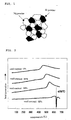
- Fig. 3 is a schematic view showing a composite powder sample obtained by this preparation step
- Fig. 4 shows an image observed by an optical microscope of a composite powder sample actually obtained by the preparation step.
- Fig. 3 shows that Si particles are dispersed in the matrix.
- Fig. 4 also shows that Si particles (white color) are dispersed in the matrix (black background).
- the preparation step may be performed in various environments such as in the air.
- the step is desirably performed under an inert gas atmosphere such as nitrogen gas and argon gas.
- a container is filled with the resulting composite powder and a pressure is applied thereto, thereby obtaining a compressed powder molded body or a magnesium-base composite material precursor.
- a method of applying a pressure and for solidifying the powder so as to obtain the precursor or the compressed powder molded body processes which have been used in a conventional powder metallurgy method may be adopted.
- a method in which a container is filled with mixed powder, thereby performing a cold isostatic pressing (CIP) thereon; or a method in which a mold is filled with powder and is compressed by upper and lower punches to form a compressed powder body may be used, but not limited thereto.
- the pressure at the time of the filling and pressure-applying step is preferably set to not less than 4 t/cm 2 to not more than 8 t/cm 2 .
- the upper limit of the pressure is set because of the following reasons. In other words, even when a high pressure is applied, only small effects are obtained in an increase in the density of the finally obtained composite material. Moreover, when a high pressure is applied, agglutination occurs between the metal mold and the molded body to be used, resulting in degradation in the service life of the metal mold; therefore, this is not preferable.
- the magnesium-base composite material precursor or compressed powder molded body preferably has a heat-generation peak, derived from the synthesizing reaction of Mg 2 Si, of 150 to 650°C, more preferably 150 to 350°C, in the measurements by the differential scanning calorimetry (DSC).
- a heat-generation peak derived from the synthesizing reaction of Mg 2 Si, of 150 to 650°C, more preferably 150 to 350°C, in the measurements by the differential scanning calorimetry (DSC).
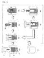
- Fig. 5 shows the results of DSC measurements of the following three samples.
- (1) With respect to the matrix powder containing Mg, 63.4 g of pure Mg (particle size: 111 ⁇ m) and 36.6 g of Si powder (particle size: 38 ⁇ m) are ground, mixed, press-bonded and crushed for 2 hours in a ball mill to prepare composite powder in which fine Si particles are dispersed in a matrix of Mg powder. This powder is used as a sample of the present invention in a powder state without making a compressed powder molded body.
- (2) The same components as the sample (1) are simply mixed, and a pressure of 5.8 t/cm 2 is applied thereto to obtain a sample (void content: 9%).
- (3) The same components as the samples (1) and (2) are simply mixed, and a pressure of 1.8 t/cm 2 is applied thereto to obtain a sample (void content: 52%).
- the above-mentioned precursor or compressed powder molded body is heated, so that Mg in the matrix powder and Si powder are allowed to react with each other to form Mg 2 Si, thereby obtaining the magnesium-base composite material of the present invention.
- the heating atmosphere is preferably prepared as an inert gas atmosphere such as nitrogen gas or argon gas, or a vacuum state for the purpose of suppressing oxidation in Mg in the matrix (precursor or compressed powder molded body) or an Mg containing alloy.
- the heating temperature is preferably set to not less than 150°C to not more than 350°C.
- the heating temperature is desirably set to not less than 200°C.
- a predetermined temperature is preferably maintained for a predetermined period of time.
- the maintaining time is preferably set to not more than 1 minute to not less than 30 minutes.
- a plastic treatment process such as a warm forging method and a warm extrusion method, is preferably further included.
- voids in the material are closed so that it is possible to increase the density of the composite material, and consequently to further improve the mechanical characteristics thereof.
- a method in which the composite material immediately after the heating step is directly subjected to a warm plasticization treatment and a method in which, after the heating step, the composite material is again heated, and then subjected to a warm plasticization treatment are listed.
- the former method is more advantageous.
- Mg 2 Si has the following characteristics.
- the grain size of Mg 2 Si is set to 10 to 200 ⁇ m with the Mg 2 Si grains being formed in a dispersed state in the resulting magnesium-base composite material.
- Mg 2 Si has a thermal expansion coefficient smaller than that of magnesium and high rigidity and high hardness, and are also excellent in heat resistance and corrosion resistance with a low specific gravity.
- the resulting magnesium-base composite material of the present invention has excellent characteristics, such as excellent mechanical characteristics and corrosion resistance.
- the composite material having these excellent characteristics is preferably designed so that the amount of Mg 2 Si contained therein is set to not less than 3 wt%, more preferably not less than 5 wt%, with respect to 100 wt% of the composite material.
- the composite material of the present invention has at least either one kind of the following properties (A) and (B) or various combined properties of not less than two kinds thereof.
- the tensile strength can be measured by using a method in accordance with Japanese Industrial Standard (JIS). Moreover, the tensile strength can also be measured by a method which will be described in examples. In other words, the tensile strength is measured in the following manner: test pieces, each having a diameter of ⁇ 3. 5 mm and a parallel portion of 14 mm, are prepared, and each test piece is attached to a 10 ton autograph, and a tensile load is applied thereto at a shifting speed of 0.5 mm/min to perform a tensile test; thus, a value obtained by dividing the load at which the test piece has been ruptured by the rupture area of the sample may be measured as the tensile strength.
- JIS Japanese Industrial Standard
- the manufacturing method i.e., the powder metallurgy method, of the present invention
- Mg in the matrix is allowed to have fine crystal grains with Mg 2 Si being also finely dispersed in the matrix so that it becomes possible to prepare a magnesium-base composite material having the above-mentioned excellent characteristics, such as excellent mechanical characteristics and corrosion resistance, with high economical efficiency.
- the resulting composite material and the precursor or compressed powder molded body have a small dimensional variation since they are manufactured through processes having no liquid phase of Mg. Therefore, the small dimensional variation between the precursor and the composite material (i.e., final product) forms one of advantages that is different from those of conventional methods.
- a magnesium-base composite material C and a manufacturing method C thereof which will be described below.
- magnesium silicide (Mg 2 Si) is dispersed in the matrix containing magnesium (Mg), and the amount of Si is set to not less than 2.5 parts by weight to not more than 10 parts by weight and the amount of Mg 2 Si is set to not less than 3 parts by weight to not more than 27.5 parts by weight, with respect to 100 parts by weight of the magnesium-base composite material, and the tensile strength of the magnesium-base composite material is set to not less than 100 MPa to not more than 500 MPa.
- the magnesium-base composite material contains magnesium silicide (Mg 2 Si) and magnesium (Mg) serving as a matrix.
- the material may be composed of these two components, or may contain other components.
- magnesium oxide (MgO), silica (SiO 2 ) and various components used for manufacturing the material are listed.
- the other components to be added may not impair the above-mentioned characteristics, e.g., the tensile strength.
- the other components to be added may not impair characteristics such as hardness (Micro Vickers hardness and/or Rockwell hardness (E scale)), which will be described later, rigidity and corrosion resistance.
- the magnesium-base composite material of the present invention preferably contains Si the amount of which is set to not less than 2 parts by weight to not more than 10 parts by weight, more preferably not less than 2.5 parts by weight to not more than 6 parts by weight, with respect to 100 parts by weight of the material.
- Si the amount of which is set to not less than 2 parts by weight to not more than 10 parts by weight, more preferably not less than 2.5 parts by weight to not more than 6 parts by weight, with respect to 100 parts by weight of the material.
- the Si amount is set in the same manner.
- the Si amount is too small, the composite material tends to fail to exert desired characteristics, in particular, mechanical characteristics.
- the characteristic values in particular, mechanical characteristic values tend to be saturated.
- the resulting composite material tends to have degradation in the toughness.
- the magnesium-base composite material of the present invention preferably contains Mg 2 Si the amount of which is set to not less than 3 parts by weight to not more than 27.5 parts by weight, more preferably not less than 6.8 parts by weight to not more than 15 parts by weight, with respect to 100 parts by weight of the material.
- the Mg 2 Si grains are preferably dispersed.
- the grain size of Mg 2 Si is preferably set to not more than 10 nm to not less than 30 ⁇ m, more preferably not more than 100 nm to not less than 10 ⁇ m. In general, as the grain size of Mg 2 Si becomes smaller, the mechanical properties of the magnesium-base composite material are further improved.
- the tensile strength is set to not less than 100 MPa to not more than 500 MPa, more preferably greater than 350 MPa to not more than 500 MPa, still more preferably 380 to 450 MPa.
- the magnesium-base composite material preferably has a Micro Vickers hardness (Hv) of 80 to 125, preferably 80 to 110, more preferably 85 to 105, and/or a Rockwell hardness of 40 to 120, preferably 80 to 105. Furthermore, its rigidity is preferably set to 47 to 65 GPa, more preferably 48 to 55 GPa. With such mechanical properties, this material is desirably applied to the above-mentioned products. Since conventional industrial Mg alloys have a tensile strength of approximately 200 to 350 MPa, the magnesium-base composite material of the present invention has excellent mechanical properties in comparison with these.
- Hv Micro Vickers hardness
- the magnesium-base composite material of the present invention containing Mg 2 Si makes it possible to greatly improve the value thereof.
- the Mg-base composite material which has Mg 2 Si grains having the above-mentioned grain-size range evenly dispersed in the material, makes it possible to greatly improve the hardness thereof.
- Mg 2 Si has high rigidity and high hardness, as well as excellent corrosion resistance and heat resistance, in comparison with Mg.
- the present inventors have found that, when Mg 2 Si is contained in an Mg alloy as dispersed grains, in particular, with its grain size being set to 10 nm to 30 ⁇ m, the resulting Mg-base composite material is allowed to have improved tensile strength, rigidity and hardness as well as improved corrosion resistance and heat resistance.
- the grain size of Mg 2 Si is preferably set in a range from 100 nm to 10 ⁇ m in an attempt to achieve both of excellent characteristics and economical efficiency.
- the controlling processes of the grain size of Mg 2 Si are performed by using, for example, methods described below; i.e., plastic treatments to be performed repeatedly on the mixed material filling a metal mold and adjustments of the succeeding heating conditions (heating temperature).
- MgO When dispersed in the Mg-base composite material, MgO makes it possible to improve the mechanical characteristics of the composite material in the same manner as Mg 2 Si. Simultaneously, MgO also has an effect for alleviating an opponent attacking property. In other words, MgO is harder than Mg alloys, and has a lower hardness in comparison with Mg 2 Si; therefore, even when used in sliding-contact with an opponent material, it is possible to prevent MgO from attacking the opponent material seriously.
- MgO grains having a grain size in the same range as that of Mg 2 Si i.e., a grain size of 10 nm to 30 ⁇ m, more preferably 100 nm to 10 ⁇ m, are evenly dispersed so that it is possible to provide an improved opponent-attacking property.
- SiO 2 which is an oxide, also alleviates the opponent-attacking property when dispersed in the magnesium-base composite material.
- SiO 2 is allowed to react with Mg to be reduced and decomposed upon generating Mg 2 Si and MgO.
- one portion of SiO 2 is allowed to remain in the composite material without reaction.
- the present invention provides a manufacturing method "C" of Mg-base composite material.
- the manufacturing method C of the present invention includes the steps of: (a) blending a first material containing Mg and a second material containing Si at a predetermined ratio to prepare a blended material; (b) performing a plastic treatment on the resulting blended material to form a solid body; (c) heating the solid body to allow Mg and Si to react with each other, thereby forming a heat solid body containing Mg 2 Si; and (d) performing a warm plasticization treatment on the heat solid body, and this method provides a magnesium-base composite material in which magnesium silicide (Mg 2 Si) is dispersed in a matrix containing magnesium (Mg).
- Mg 2 Si magnesium silicide
- the first material containing Mg is not particularly limited as long as it contains Mg, and examples thereof include pure magnesium; an Mg alloy mainly containing Mg, for example, AZ31, AZ91, AM50 and AM60; and an industrial magnesium alloy such as a ZK-based alloy.
- the particle size is preferably set to not less than 10 ⁇ m, more preferably not less than 50 ⁇ m, from the viewpoint of explosion prevention such as a powder explosion.
- the shape of the first material is not particularly limited as long as it satisfies the above-mentioned point, and it is preferably prepared as shapes such as chips, powder and small granulates. For example, a so-called thixo-mold-use material may be used.
- the second material containing Si is not particularly limited as long as it contains Si, and examples thereof include Si itself, silica and SiO 2 .
- the particle size is set in a wide range of sizes, for example, from a coarse material having a block shape with a unit of several centimeters to fine particles in a level of several microns that have been subjected to a mechanical grinding process.
- various weighing capacities of the respective materials and mixtures thereof are adopted. These steps are performed in the same methods as those conventionally used in the powder metallurgical field.
- conventionally known means such as a mixing grinder, for example, a V-type mixer and a ball mill, may be used.
- the mixing process may be performed in the air without causing any problems; however, it is preferably performed in a nitrogen or argon gas atmosphere so as to prevent oxidation on, for example, the powder surface of pure Mg powder. More specifically, in the case where fine particles are used, the mixing process is preferably performed with a mixing container filling the fine particles as well as nitrogen gas, argon gas or the like.
- the resulting blended material is then subjected to a solid body forming step of forming a solid body through a plastic treatment.
- the plastic treatment may be performed by using various means, and, for example, the methods described in the above-mentioned manufacturing methods (A) and (B) may be used.
- the blended matter is prepared as mixed powder of the first sample and the second sample, and the plastic treatment may be performed by filling the container with the mixed powder and applying a pressure thereto to obtain a solid body as a compressed powder molded body having a void content of not more than 35%.
- the blended material is prepared as an aggregate of composite powder in which Si is dispersed in matrix powder containing Mg, and the plastic treatment is performed by filling the container with the aggregate of the composite powder and applying a pressure thereto to obtain a solid body as a compressed powder molded body.
- the plastic treatment may be performed in the following manner: after filling a metal mold or a container with a blended material, the blended material is compressed and deformed, or extruded and deformed, or backward-extruded, and a desired combination of these operations is performed a plurality of times, so that the respective samples in the blended matter are mixed and/or ground and finally compressed to provide a solid body.
- the solid body forming steps are performed in such a manner that the solid body is preferably formed so as to contain Mg 2 Si grains having a grain size of not less than 10 nm to not more than 30 ⁇ m, more preferably not more than 1 ⁇ m, or Mg 2 Si grains having a grain size of not less than 10 nm to not more than 30 ⁇ m, more preferably not more than 1 ⁇ m, and a second material having a grain size of not less than 10 nm to not more than 30 ⁇ m, more preferably not more than 3 ⁇ m.
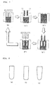
- Figs. 6(a) is a schematic view showing a state where a container constituted by a metal mold 1 and a lower punch 3 is filled with a blended material 5.
- blended material 5 is subjected to plastic treatments (b) to (f).
- Plastic treatments (b) to (f) are performed by using a press machine having a compression upper punch 7 and a pushing upper punch 9.
- the press machine used in this case, may be a press machine with any of the conventional driving systems such as a hydraulic system, a mechanical system and a screw system.
- the lowering speed of the punch is desirably set at a high speed, for example, approximately 50 to 500 mm/sec by using, for example, a screw-type press.
- step (b) compression upper punch 7 is lowered into the metal mold so that the blended and mixed power is compressed and solidified to obtain compressed body 8.
- step (d) pushing upper punch 9 is lowered into metal mold 1.
- compressed body 8 is extruded backward (in the direction indicated by arrow B) so that a plastic treatment is applied thereto; thus, the first material containing Mg and the second material containing Si are mechanically ground and formed into fine particles.
- step (e) compression upper punch 7 is again lowered into metal mold 1 to again compress the compression matter that has been formed into a U-shape as shown in Fig. 6(f).
- the solid body located along the inner face of metal mold 1 is allowed to reach the inside of metal mold 1 (in the direction indicated by arrow C).
- the sequence of these steps (b) to (f) is performed once, or repeated a plurality of times so that the first and second materials in blended power 5 are further mixed and stirred, and formed into fine powder.
- the sequence of steps (b) to (f), that is, the compressing process (pressure-applying and compressing processes by compression upper punch 7) and the backward extruding plastic treatment by pushing upper punch 9, is set as one cycle, and by repeating a predetermined number of cycles so as to evenly mix and grind the first and second materials, Mg 2 Si is synthesized through a solid-phase dispersing phenomenon by adjusting the number of cycles.
- the plastic treatment amount to be applied to the blended power is controlled so that the grain size of Mg 2 Si in the finally obtained composite material is adjusted, for example, in a range of 10 to 500 nm.
- the plastic treatment amount is controlled by changing various parameters. For example, with respect to these parameters, the relative density of the solid body obtained by a compression on the final stage of this process, the number of cycles of (b) to (f), the relationship between the load and speed of pushing upper punch 9 in (b) as well as the relationship between the inner diameter of metal mold 1 and the outer diameter of pushing upper punch 9, and the load and speed of compression upper punch 7 in (f) are listed.
- metal mold 1 is reversed upside down with an interval of predetermined cycles if necessary, or after the blended and mixed matter has been taken out, the blended and mixed power is reversed upside down so as to again perform the compressing and backward extruding processes.
- the step (b) is performed so that a solid body having a cylinder shape (Fig. 6(g)) can be obtained.
- the solid body is allowed to contain (a) Mg 2 Si grains having a grain size of not less than 10 nm to not more than 30 ⁇ m, preferably not more than 1 ⁇ m, or (b) Mg 2 Si grains having a grain size of not less than 10 nm to not more than 30 ⁇ m, preferably not more than 1 ⁇ m, and a second material (for example, Si particles or SiO 2 particles) having a particle size of not less than 10 nm to not more than 30 ⁇ m, preferably not more than 3 ⁇ m.
- a second material for example, Si particles or SiO 2 particles
- pushing upper punch 9 shown in Fig. 6 instead of pushing upper punch 9 shown in Fig. 6, two pushing upper punches 11 may be used, or not less than three pushing upper punches may be used.
- the shape, material and the like of the pushing upper punch may have shapes indicated by, for example, Figs. 8(a) to (c) so that the blended material is not subjected to agglutination and burning phenomena onto the punch top portion during the backward extruding process at the time of insertion.
- a spherical shaped curvature in the vicinity of the tip end portion of the pushing upper punch, (a) a spherical shaped curvature, (b) a curvature on only the comer portion, or (c) curvatures on the taper and corner portions may be formed.
- a coating process that is excellent in anti-abrasion and self-lubricating properties such as Ni-P plating, Cr plating, DLC (Diamond Like Carbon) and a nitriding process, may be applied to the punch surface.
- the solid body obtained by the solid body forming step has a relative density of approximately 75 to 95%, with the first material particles being insufficiently joined to each other; therefore, the solid body is then subjected to a heating step and a warm plasticization treatment step so as to have a finer structure.
- the heating step makes it possible (1) to allow the first material to be easily deformed in the succeeding warm plasticization step and (2) to allow unreacted portion of the second sample, for example, Si or SiO 2 if any, to perform a solid phase reaction with Mg.
- the heating temperature of the solid body is set to not less than 150°C to not more than 600°C, more preferably not less than 350°C to not more than 520°C.
- the heating temperature is less than 150°C, it is not possible to obtain the effects of the above-mentioned (1), and it is also not possible to obtain a sufficient joining strength between the first material particles. Consequently, the Mg-base composite material tends to have degradation in the relative density or mechanical characteristics.
- the heating temperature exceeds 600°C the first material (in particular, Mg), which constitutes the matrix material, tends to have coarse crystal grains and growth thereof, and consequently has degradation in the mechanical characteristics in the Mg-base composite material.
- the heating temperature of the solid body is desirably set to not less than 350°C to not more than 520°C, in order to progress the solid-phase reaction stably while preventing Mg 2 Si grains thus solid-phase synthesized from becoming coarse, and to prevent degradation in the mechanical properties of the Mg-base composite material.
- the heating atmosphere is prepared as an inert gas atmosphere such as nitrogen and argon or a vacuum state.
- the following tubular furnace was prepared.
- nitrogen gas gas flow rate: 3 dm 3 /min
- the inner temperature thereof was controlled to 580°C.
- the conditions of the powder forging method were set to metal-mold temperature: 250°C; face pressure: 8 t/cm 2 , and a water-soluble lubricating agent was applied to the metal mold side walls from the viewpoint of prevention of agglutination between the solid body and the metal mold.
- Table 1 shows characteristics of the compressed powder molded bodies A-1 to A-7 obtained as described above and the magnesium-base composite materials B-1 to B7.
- the void content was a value calculated by the aforementioned method.
- Table 1 also shows the synthesizing reaction starting temperature (in Table 1, simply referred to as “reaction starting temperature") of Mg 2 Si obtained through DSC measurements, the presence or absence of an Mg liquid phase, and mechanical characteristics of the magnesium-base composite materials B-1 to B-7 (hardness, tensile strength and breaking elongation).
- Hardness measurements were performed by using a Micro Vickers hardness tester under a load of 0.49 N.
- Test pieces having a diameter: ⁇ 3.5mm and parallel portions: 14 mm were prepared. Each test piece was attached to a 10 ton autograph, and a tensile load was applied thereto at a shifting speed of 0.5 mm/min to perform a tensile test. Thus, a value obtained by dividing the load at which the test piece had been ruptured by the rupture area of the sample was measured as the tensile strength.
- the breaking elongation was calculated based on the maximum displacement amount in an area (plastic deformation area) separated from a straight line having a constant gradient in a load-displacement curve obtained on chart paper during the tensile strength testing process.
- the compressed powder molded bodies A-1 to A-5 which had a void content in accordance with the present invention, were applied so that it became possible to form Mg 2 Si in a solid phase without causing a liquid phase of Mg. Moreover, as a result, composite materials B-1 to B-5 in which fine Mg 2 Si was dispersed in a magnesium base element were obtained, and as shown in Table 1, it was confirmed that the materials had excellent mechanical characteristics.
- AZ91D magnesium alloy powder (average particle size: 61 ⁇ m; nominal composition: Mg-9A1-1Zn/mass %) and 15 parts by weight of Si powder (average particle size: 64 ⁇ m) were prepared. After blending these, the resulting material was evenly mixed by a ball mill to obtain mixed powder. A circular metal mold having a diameter of 11.3 mm was filled with the resulting mixed powder, and a load having a face pressure of 5 t/cm 2 was applied thereto, thereby forming a compressed powder molded body A-8. The void content thereof was measured to find that it showed 12.3%, which satisfied the range defined by the present invention.
- the compressed powder molded body A-8 obtained as described above, was inserted into a tubular furnace through which nitrogen gas (gas flow rate: 2 dm 3 /min) was allowed to flow, and after having been heated at the respective heating temperatures shown in Table 2 for 30 minutes, and maintained, this was cooled to normal temperature in the furnace to provide composite materials B-8 to B-14.
- nitrogen gas gas flow rate: 2 dm 3 /min
- Table 2 shows the results of these.
- the heating process in an appropriate temperature range allows the reaction between Mg and Si to progress to synthesize Mg 2 Si.
- all the added Si powder contributes to the reaction with Mg so that no Si powder remains in the material after the Mg 2 Si synthesizing reaction.
- Pure Mg powder (average particle size: 112 ⁇ m) and Si powder (average particle size: 64 ⁇ m) were prepared as starting materials, and the two materials were mixed so as to have a blended composition as shown in Table 3, thereby obtaining mixed powder.
- a circular metal mold having a diameter of 11.3 mm was filled with the resulting mixed powder, and a load having a face pressure of 6 t/cm 2 was applied thereto, thereby forming green compact molded bodies A-9 to A-15.
- the void contents of these molded bodies A-9 to A-15 were measured to obtain values of 8.9 to 11%, each of which satisfies the range defined by the present invention.
- Table 3 shows that by setting the blend ratio of Mg and Si that are starting materials to an appropriate value (A-9 to A-13), a composite material (B-15 to B-19) having excellent shape and external appearance, and containing Mg 2 Si and Mg is obtained; in contrast, when the blend ratio is not an appropriate value (A-14 and A-15), a material (B-20 and B-21) containing Mg 2 Si and Mg fails to have sufficient strength, and is susceptible to damages upon transportation is obtained.
- Pure Mg powder (average particle size: 223 ⁇ m) and Si powder (average particle size: 105 ⁇ m) were prepared as starting materials, and the two materials were mixed so as to have a blended composition as shown in Table 4, thereby obtaining mixed powder.
- a circular metal mold having a diameter of 34 mm was filled with the resulting mixed powder, and a load having a face pressure of 6 t/cm 2 was applied thereto, thereby forming compressed powder molded bodies A-16 to A-22.
- the void contents of these molded bodies A-16 to A-22 were measured to obtain values of 8.3 to 10.7%, each of which satisfies the range defined by the present invention.
- the conditions of the powder forging method were set to metal-mold temperature: 250°C; face pressure: 8 t/cm 2 , and a water-soluble lubricating agent was applied to the metal mold side walls from the viewpoint of prevention of agglutination between the solid body and the metal mold.
- the average corrosion speed was measured.
- a cube (10 mm ⁇ 10 mm ⁇ 10 mm in thickness) was taken from each of the materials B-22 to B-28 through a machining process, and this was then polished by emery paper to prepare a test piece.
- This test piece was evaluated on its corrosion resistance by using a 5% salt-water atomizing test (100 hr).
- the average corrosion speed was calculated from weight changes before and after the test, and used as indexes of the corrosion resistance evaluation.
- Table 4 also shows the results thereof.
- Table 4 also shows the amount of Mg 2 Si (calculated value from blended composition).
- Table 4 shows that the composite materials B-22 to B-26 have excellent corrosion resistance. In contrast, the materials B-27 and B-28, which contain a small amount of Mg 2 Si, are poor in corrosion resistance.
- the following tubular furnace was prepared.
- nitrogen gas gas flow rate: 3 dm 3 /min
- the inner temperature thereof being controlled in the vicinity of 100 to 500°C shown in Table 1
- the conditions of the powder forging method were set to metal-mold temperature: 250°C; face pressure: 8 t/cm 2 , and a water-soluble lubricating agent was applied to the metal mold side walls from the viewpoint of prevention of agglutination between the solid body and the metal mold.
- Table 101 shows characteristics of the compressed powder molded body A-101 or A-102 and the magnesium-base composite materials B-101 to B-110.
- Table 101 “the presence or absence of Mg 2 Si” was observed through X-ray diffractions. Further, “the hardness” is a value obtained by a Rockwell tester of scale E. "The tensile strength” was measured by the above-mentioned method.
- Run Nos. 101 to 105 which used composite powder in accordance with the present invention and had a low heating temperature in a range of 150°C to 343°C, made it possible to obtain a composite material with high hardness.
- Run Nos. 106 and 107 were confirmed to generate Mg 2 Si since it used composite powder in accordance with the present invention; however, its hardness was lower than desired hardness. This is because the heating temperature was too high to allow Mg 2 Si particles to become coarse.
- Run No. 108 was not confirmed to generate Mg 2 Si since its heating temperature was too low, and also failed to provide sufficient hardness.
- Runs Nos. 109 and 110 did not use composite powder in accordance with the present invention, and its heating temperature was too low; therefore, Runs Nos. 109 and 110 were not confirmed to generate Mg 2 Si. Of course, these failed to provide sufficient hardness.
- AZ91D magnesium alloy powder (average particle size: 61 ⁇ m; nominal composition: Mg-9A1-1Zn/mass %) and 10 parts by weight of Si powder (average particle size: 64 ⁇ m) were prepared. After blending these, the resulting material was mechanically ground, mixed and press-bonded for 4 hours by using a vibration ball mill to obtain composite powder. A circular metal mold having a diameter of 34 mm was filled with the resulting composite powder, and a load having a face pressure of 6 t/cm 2 was applied thereto, thereby forming a green compact molded body A-103.
- the following tubular furnace was prepared.
- nitrogen gas gas flow rate: 3 dm 3 /min
- the inner temperature thereof being controlled in the vicinity of 80 to 530°C shown in Table 1
- the conditions of the powder forging method were set to metal-mold temperature: 250°C; face pressure: 8 t/cm 2 , and a water-soluble lubricating agent was applied to the metal mold side walls from the viewpoint of prevention of agglutination between the solid body and the metal mold.
- Table 102 shows characteristics of the compressed powder molded body A-103 or A-104 and the magnesium-base composite materials B-111 to B-120.
- Table 102 “the presence or absence of Mg 2 Si” was observed through X-ray diffractions. Further, “the hardness” is a value obtained by a Rockwell tester of scale E in the same manner as described above.
- Run Nos. 111 to 115 which used composite powder in accordance with the present invention and had a low heating temperature in a range of 150°C to 346°C, made it possible to obtain a composite material with high hardness.
- Run Nos. 116 and 117 were confirmed to generate Mg 2 Si since it used composite powder in accordance with the present invention; however, its hardness was lower than desired hardness. This is because the heating temperature was too high to make Mg 2 Si particles become coarse.
- Run No. 118 was not confirmed to generate Mg 2 Si since its heating temperature was too low, and also failed to provide sufficient hardness.
- Runs Nos. 109 and 110 did not use composite powder in accordance with the present invention, and its heating temperature was too low; therefore, Runs Nos. 109 and 110 were not confirmed to generate Mg 2 Si. Of course, they failed to provide sufficient hardness.
- a disc (diameter 50 mm, thickness 3 mm) made of pure Mg (pureness 99.85%) and the composite powder X-101 of example 101 were prepared.
- the disc was prepared with the composite powder X-101 being placed on one surface of the disc, and this was inserted into a furnace through which nitrogen gas (gas flow rate: 3 dm 3 /min) with the temperature thereof being controlled to 160°C, and heated and maintained for 5 minutes. Thereafter, a face pressure 8 t/cm 2 was applied thereto by using a hydraulic press so that a clad plate member on which the magnesium-base composite powder adhered to the magnesium round plate was formed. This was again inserted into the furnace in an nitrogen gas atmosphere, and heated at a temperature of 250°C and maintained for 10 minutes.
- the presence or absence of any Mg 2 Si peak was confirmed by X-ray diffraction, and after having been polished by emery paper, this was then evaluated on its corrosion resistance by using a 5% salt-water atomizing test (100 hr). The average corrosion speed was calculated from weight changes before and after the test, and used as indexes of the corrosion resistance evaluation.
- the average corrosion speed on the clad surface side was 0.014 g/m 2 /hr; in contrast, the average corrosion speed on the Mg plate member without cladding was 0.21 g/m 2 /hr. In other words, it was confirmed that the magnesium-base composite material with cladding makes it possible to improve the corrosion resistance greatly.
- AZ31D magnesium alloy powder (average particle size: 252 ⁇ m) and Si powder (average particle size: 42 ⁇ m) were prepared as starting materials. After blending the AZ31 powder and Si powder at a ratio shown in Table 201, the resulting material was evenly mixed by using a ball mill to obtain mixed powder. Next, 25 g of each mixed powder was put into a cylindrical metal mold (made of cemented carbide alloy) having an inner diameter of 35 mm, attached to a 100 ton screw-type press-working machine. As shown in Figs. 6(a) to 6(g), a plastic treatment by using a backward extrusion method using a pushing punch (made of SKD 11 steel) was repeatedly performed to finally obtain a solid body.
- the diameter of the pushing punch was 28 mm, and the punch top portion had a semi-circular shape with a radius of 14 mm.
- the relative density of the solid body was 88%, and the entire length (height) of the solid body was 30 mm.
- the number of cycles shown in Table 201 was used.
- one time of a pressure applying process by the compression punch and one time of a backward extrusion process by the insertion of the pushing punch are set to one cycle.
- each of the resulting solid body was inserted into a tubular furnace (inner furnace temperature: 500°C) through which nitrogen gas (gas flow rate: 3 dm 3 /min) was allowed to flow, and heated and maintained for 10 minutes, and the resulting molded body was taken out of the furnace, and this was immediately subjected to a warm extrusion method to obtain rod-shaped magnesium-base extruded composite materials M-1 to M-13 having a diameter of 7 mm.
- the warm extrusion conditions were: extrusion die temperature: 300°C and extrusion ratio: 37.
- Mg-base composite materials M-1 to M-9 With respect to Mg-base composite materials M-1 to M-9, it was confirmed that Mg 2 Si grains were dispersed in each of the resulting Mg-base composite materials through structure observations by using an optical microscope, a scanning electron microscope (SEM) and a transmission-type electron microscope (TEM).
- SEM scanning electron microscope
- TEM transmission-type electron microscope
- the Mg-base composite materials M-1 to M-9 were desired mechanical characteristics such as tensile strength, Vickers hardness and rigidity. These mechanical characteristics are dependent on the amount of Si and the number of cycles of plastic treatment used upon preparation of the composite material and Mg 2 Si particle sizes in the resulting material.
- the resulting Mg-base composite material M-10 was poor in the mechanical characteristics such as tensile strength, Vickers hardness and rigidity, and failed to provide desired characteristics.
- the Mg-base composite material M-11 contained Si powder as its starting material, the amount thereof was set to a low level of 1%; therefore, the resulting Mg-base composite material M-11 was poor in the mechanical characteristics, and failed to provide desired characteristics.
- the amount of Si serving as its starting material was set to a high level of 13% so that desired characteristics were obtained in its mechanical characteristics (tensile strength, Vickers hardness and rigidity); however, the toughness (elongation) thereof was considerably lowered to 0%, causing a problem with the cutting property of the extruded material due to tool abrasion.
- the Mg-base composite material M-13 was a material obtained by simply applying a compressing process to the mixture of the AZ31 alloy powder and Si powder without applying the repeated plastic treatment thereto. Therefore, the Si particles were not sufficiently ground, with the result that the Mg 2 Si grain size (35 to 52 ⁇ m) in the resulting Mg-base extruded composite material M-13 was approximately the same as the particle size (average particle size: 42 ⁇ m) of Si powder serving as the starting material, which was relatively large; consequently it was not possible to provide desired mechanical properties.
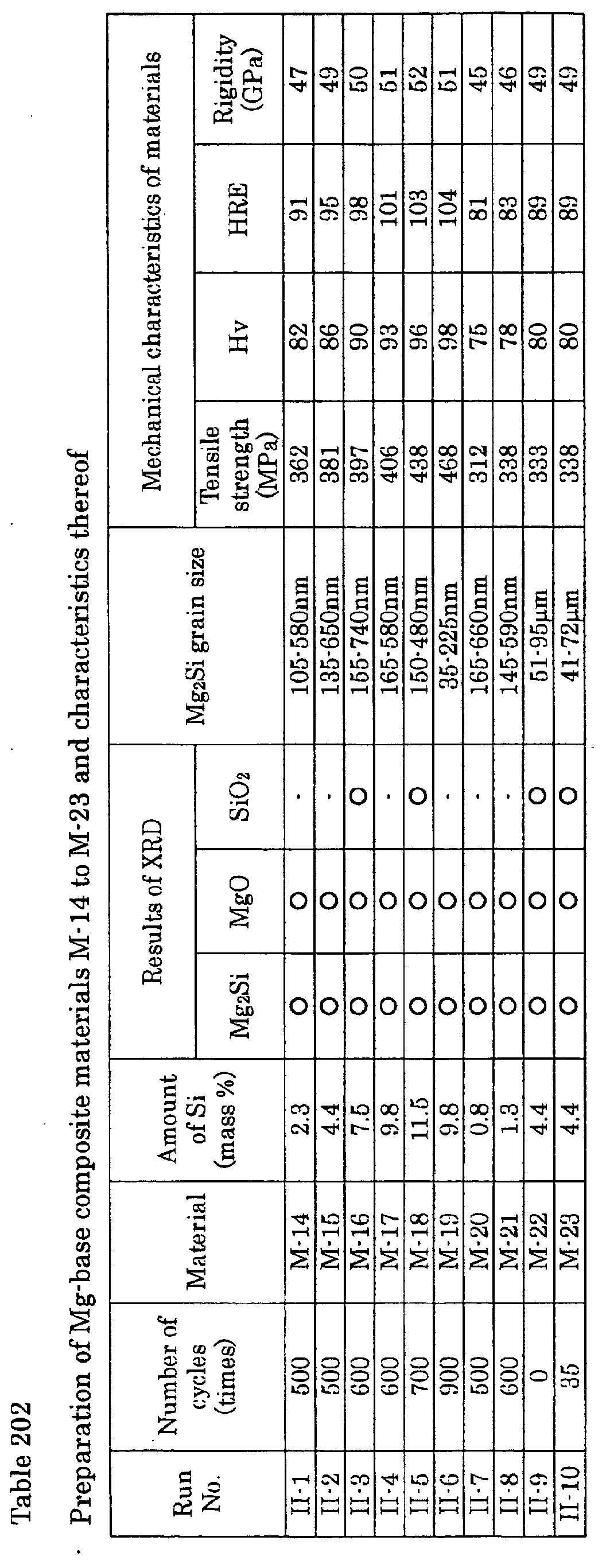
- AM60 magnesium alloy chips (length: 2 to 5 mm) and SiO 2 powder (average particle size: 68 ⁇ m) were prepared as starting materials. After blending these two materials at a ratio shown in Table 202, the resulting material was evenly mixed by using a ball mill to obtain mixed powder. Next, 25 g of each mixed powder was injected into a cylinder-shaped metal mold (made of cemented carbide alloy) having an inner diameter of 35 mm, attached to a 100 ton screw-type press-working machine. As shown in Figs. 6(a) to 6(g), a plastic treatment by using a backward extrusion method using a pushing-use punch (made of SKD 11 steel) was repeatedly performed to finally obtain a solid body.
- the diameter of the pushing punch was 28 mm
- the punch top portion had a semi-circular shape with a radius of 14 mm.
- the relative density of the solid body was 88%
- the entire length (height) of the solid body was 30 mm.
- the number of cycles shown in Table 202 was defined in the same manner as Example 201.
- Each of the resulting solid body was inserted into a tubular furnace (inner furnace temperature: 520°C) through which nitrogen gas (gas flow rate: 3 dm 3 /min) was allowed to flow, and heated and maintained for 10 minutes, and the resulting molded body was taken out of the furnace, and this was immediately subjected to a warm extrusion method to obtain rod-shaped magnesium-base extruded composite materials M-14 to M-23 having a diameter of 7 mm.
- nitrogen gas gas flow rate: 3 dm 3 /min
- the warm extrusion conditions were extrusion die temperature: 300°C and extrusion ratio: 37.
- the Si component amount was analyzed by ICP. Moreover, the presence or absence of the generated or remaining Mg 2 Si/MgO/SiO 2 was confirmed by using X-ray diffraction (XRD). Furthermore, with respect to the magnesium-base extruded composite materials M-14 to M-23, the tensile strength ⁇ , Micro Vickers hardness Hv, Rockwell hardness (E scale) HRE and rigidity (Young's Modulus) were measured. Table 202 shows the results thereof. Table 202 also shows the grain sizes of Mg 2 Si calculated in the same method as example 201.
- the Mg-base composite materials M-14 to M-19 had desired mechanical characteristics.
- the grain size of Mg 2 Si grains dispersed in the composite material was set to 10 nm to 30 ⁇ m, in particular, 10 nm to 800 nm.
- Table 202 even when the composite material contained MgO or MgO and SiO 2 , it was allowed to exert desired mechanical characteristics.
- any of the magnesium-base extruded composite materials M-20 to M-23 failed to provide desired tensile strength. The reasons for this are described as follows.
- Table 202 shows that, with respect to the composite materials M-20 and M-21, all the Si component contained in the material has been formed into Mg 2 Si; however, it is considered that, since the amount thereof is small, desired mechanical properties are not obtained.
- the composite material M-22 was a material obtained by simply applying a compressing process to the starting material without applying the repeated plastic treatment thereto. Therefore, the Mg 2 Si grain size (51 to 95 ⁇ m) in the resulting Mg-base extruded composite material was approximately the same as the particle size (average particle size: 68 ⁇ m) of SiO 2 powder serving as the starting material. Consequently, the SiO 2 powder was not finely ground, and it was not possible to provide desired mechanical properties.
- the repeated plastic treatment was performed; however, since the number of cycles was small, the SiO 2 powder was not finely ground in the same manner as the composite material M-22, and it was not possible to provide desired mechanical properties.
- AZ31 magnesium alloy powder (average particle size 252 ⁇ m) and Si powder (average particle size: 42 ⁇ m) were prepared as starting materials.
- the AZ31 powder and Si powder were blended at an Si content of 5% on the weight basis.
- the resulting material was evenly mixed by using a ball mill to obtain mixed powder.
- 25 g of each mixed powder was put into a cylindrical metal mold (made of cemented carbide alloy) having an inner diameter of 35 mm, attached to a 100 ton screw-type press working machine.
- a plastic treatment by using a backward extrusion method using a pushing-use punch (made of SKD 11 steel) was repeatedly performed to finally obtain solid bodies S-1 to S-10.
- the diameter of the pushing punch was 30 mm, and the punch top portion had a semi-circular shape with a radius of 15 mm.
- the applied pressure by the compression punch was adjusted so as to set the relative density of the resulting solid body to a value shown in Table 203.
- the number of cycles shown in Table 203 was defined in the same manner as example 201.
- the solid bodies S-1 to S-7 which were obtained by sufficiently performing the repeated plastic treatment, had Mg 2 Si grains that had been formed into fine grains. Therefore, it is confirmed that the repeated plastic treatment processes make it possible to solid-phase synthesize fine Mg 2 Si grains. Moreover, the solid bodies S-1 to S-6 had fine Si grains. The solid bodies S-1 to S-6 having fine, unreacted Si grains are then subjected to a heating process and a warm plasticization treatment process so that it also becomes possible to synthesize all the unreacted Si grains into Mg 2 Si grains.
- the Mg 2 Si grains obtained through these processes, are dependent on the grain size of the unreacted Si grains so that the Mg 2 Si grains of the Mg-base composite material, obtained by performing heating steps and warm plasticization treatment steps on the solid bodies S-1 to S-6, are allowed to have a fine structure.
- the solid bodies S-8 to S-10 were not subjected to the repeated plastic treatment (S-8), or were not subjected to a sufficient amount of repeated plastic treatment (S-9 and S-10); therefore, the resulting grain size of Mg 2 Si became approximately 30 ⁇ m or more.
- the unreacted Si grains, contained in the solid bodies S-8 to S-10, were also set to approximately 30 ⁇ m or more. Therefore, it is considered that, even when the solid bodies S-8 to S-10 are then subjected to the heating process and warm plasticization treatment process, the grain size of the resulting Mg 2 Si becomes approximately 30 ⁇ m or more, depending on the unreacted Si grain size.
- the magnesium-base composite material of the present invention has high strength, high abrasion resistance and high corrosion resistance in addition to its light-weight property, it is applicable to structural part materials, such as car parts and electric appliance parts, in which these properties are simultaneously demanded, as well as medical and welfare tools and protective tools such as caring beds, wheel chairs, canes and go-carts.
- the magnesium-base composite powder used in the manufacturing method of the present invention is applicable in the following manner: the powder is subjected to a plastic treatment such as pressing-compressing/rolling processes at normal temperature or a warm temperature, while being placed on a magnesium alloy plate, and then subjected to the heating step used in the present invention so that a clad plate member in which the magnesium-base composite powder of the present invention is contact-bonded to the magnesium alloy plate is formed.
- the clad plate member in which Mg 2 Si particles are dispersed only in the surface of the magnesium alloy plate, with the Mg 2 Si particles being firmly joined to the magnesium alloy plate can be prepared.
- This clad plate member has excellent corrosion resistance and abrasion resistance because of the Mg 2 Si grains that have been evenly dispersed, and suitably applied to structural parts such as light-weight pipes.
- the magnesium-base composite material of the present invention is subjected to secondary and/or tertiary processes such as cutting, forging, bending and joining processes, if necessary, to form the following products.
- secondary and/or tertiary processes such as cutting, forging, bending and joining processes, if necessary, to form the following products.
- examples thereof include a wide range of products as shown below, and it is applicable to those products to which aluminum alloys have been conventionally applied.
- Raw materials, intermediate products, finished products and assembled products formed by various processes, such as welding, fusion welding, brazing, bonding, thermal cutting, thermal processing, forging, extruding, drawing, rolling, shearing, plate molding, roll molding, form rolling, spinning, bending, leveling, high-energy speed machining, powder machining, various cutting processes and grinding processes; and composite products in which these products are combined with other material products.
- Raw materials, intermediate products, finished products and assembled products that have been subjected to various surface treatments such as metal coating, chemical conversion coating, surface curing, non-metal coating and painting, and composite products in which these products are combined with other material products.
- Golf club parts such as a shaft, a head, a toe, a heal and a sole.
- Bicycle products such as a transmission gear, a frame and a handle.
Landscapes
- Chemical & Material Sciences (AREA)
- Organic Chemistry (AREA)
- Engineering & Computer Science (AREA)
- Materials Engineering (AREA)
- Mechanical Engineering (AREA)
- Metallurgy (AREA)
- Ceramic Engineering (AREA)
- Inorganic Chemistry (AREA)
- Manufacturing & Machinery (AREA)
- Structural Engineering (AREA)
- Powder Metallurgy (AREA)
- Manufacture Of Alloys Or Alloy Compounds (AREA)
Abstract
Description



Claims (53)
- A magnesium-base composite material comprising magnesium silicide (Mg2Si) dispersed in a matrix containing magnesium (Mg), the magnesium-base composite material having an amount of Si of not less than 2 parts by weight to not more than 10 parts by weight and an amount of Mg2Si of not less than 3 parts by weight to not more than 27.5 parts by weight, with respect to 100 parts by weight of the magnesium-base composite material, and having a tensile strength of not less than 100 MPa to not more than 500 MPa.
- A magnesium-base composite material comprising magnesium silicide (Mg2Si) dispersed in a matrix containing magnesium (Mg), the magnesium-base composite material having an amount of Si of not less than 2 parts by weight to not more than 10 parts by weight and an amount of Mg2Si of not less than 3 parts by weight to not more than 27.5 parts by weight, with respect to 100 parts by weight of the magnesium-base composite material, and having a tensile strength of more than 350 MPa to not more than 500 MPa.
- The magnesium-base composite material according to claim 1 or 2, wherein Mg2Si is dispersed in the composite material as grains, and has a grain size of not less than 10 nm to not more than 30 µm.
- The magnesium-base composite material according to claim 3, wherein Mg2Si has a grain size of not less than 100 nm to not more than 10 µm.
- The magnesium-base composite material according to any of claims 1 to 4, wherein said magnesium-base composite material further comprises magnesium oxide (MgO) and/or silica (SiO2).
- The magnesium-base composite material according to any of claims 1 to 5, wherein said magnesium-base composite material has a Micro Vickers hardness (Hv) of 80 to 125.
- The magnesium-base composite material according to any of claims 1 to 6, wherein said magnesium-base composite material has a Rockwell hardness (E scale)(HRE) of 40 to 120.
- The magnesium-base composite material according to any of claims 1 to 7, wherein said magnesium-base composite material has a rigidity of 47 to 65 GPa.
- A magnesium-base composite material comprising magnesium silicide (Mg2Si) dispersed in a matrix containing magnesium (Mg), the magnesium-base composite material having at least one kind of characteristics selected from the following groups (A) and (B):(A) said magnesium-base composite material has a Rockwell hardness (E scale) of not less than 40 to not more than 105, and/or said magnesium-base composite material has a Rockwell hardness (E scale) greater than that of a base material obtained by removing the magnesium silicide from said magnesium-base composite material by a value of not less than 20 to not more than 80; and(B) said magnesium-base composite material has a tensile strength of not less than 100 MPa to not more than 350 MPa, and/or said magnesium-base composite material has a tensile strength greater than that of said base material by a value of not less than 20 MPa to not more than 100 MPa.
- A magnesium-base composite material comprising magnesium silicide (Mg2Si) dispersed in a matrix containing magnesium (Mg), the magnesium-base composite material having a tensile strength of not less than 100 MPa to not more than 350 MPa.
- The magnesium-base composite material according to claim 10, wherein said magnesium-base composite material has a Rockwell hardness (E scale) of not less than 40 to not more than 105.
- A magnesium-base composite material comprising magnesium silicide (Mg2Si) dispersed in a matrix containing magnesium (Mg), the magnesium-base composite material having a Rockwell hardness (E scale) of not less than 40 to not more than 105.
- The material according to any of claims 9 to 12, wherein said Mg2Si is set to not less than 3 wt% with respect to 100 wt% of said magnesium-base composite material.
- A magnesium-base composite material comprising magnesium silicide (Mg2Si) dispersed in a matrix containing magnesium (Mg), the magnesium-base composite material having at least one kind of characteristics selected from the following groups (A) and (B):(A) said magnesium-base composite material has a Rockwell hardness (E scale) of not less than 40 to not more than 95, and/or said magnesium-base composite material has a Rockwell hardness (E scale) greater than that of a base material obtained by removing the magnesium silicide from said magnesium-base composite material by a value of not less than 20 to not more than 40; and(B) said magnesium-base composite material has a tensile strength of not less than 100 MPa to not more than 280 MPa, and/or said magnesium-base composite material has a tensile strength greater than that of said base material by a value of not less than 20 MPa to not more than 50 MPa.
- A magnesium-base composite material comprising magnesium silicide (Mg2Si) dispersed in a matrix containing magnesium (Mg), the magnesium-base composite material having a tensile strength of not less than 100 MPa to not more than 280 MPa.
- The magnesium-base composite material according to claim 15, wherein said magnesium-base composite material has a Rockwell hardness (E scale) of not less than 40 to not more than 95.
- A magnesium-base composite material comprising magnesium silicide (Mg2Si) dispersed in a matrix containing magnesium (Mg), the magnesium-base composite material having a Rockwell hardness (E scale) of not less than 40 to not more than 95.
- The material according to any of claims 14 to 17, wherein said Mg2Si is set to not less than 3 wt% with respect to 100 wt% of said magnesium-base composite material.
- The magnesium-base composite material according to any of claims 9 to 18, wherein Mg2Si is dispersed in the composite material as grains, and has a grain size of not less than 10 nm to not more than 30 µm.
- The magnesium-base composite material according to claim 19, wherein Mg2Si has a grain size of not less than 100 nm to not more than 10 µm.
- The magnesium-base composite material according to any of claims 9 to 20, wherein Si is set to not less than 2 parts by weight to not more than 10 parts by weight with respect to 100 parts by weight of said magnesium-base composite material.
- The magnesium-base composite material according to any of claims 9 to 21, wherein Mg2Si is set to not less than 3 parts by weight to not more than 27.5 parts by weight with respect to 100 parts by weight of said magnesium-base composite material.
- The magnesium-base composite material according to any of claims 9 to 22, said magnesium-base composite material further comprises magnesium oxide (MgO) and/or silica (SiO2).
- The magnesium-base composite material according to any of claims 9 to 23, wherein said magnesium-base composite material has a Micro Vickers hardness (Hv) of 80 to 125.
- The magnesium-base composite material according to any of claims 9 to 24, wherein said magnesium-base composite material has a rigidity of 47 to 65 GPa.
- A product made of the magnesium-base composite material according to any of claims 1 to 25.
- The product according to claim 26, selected from the group consisting of: a raw material, an intermediate product, a finished product and an assembled product; a part for transport equipment; a part for electric appliance; a housing product; a part for precision machine; a sports product and a weapon; a medical instrument; and a welfare caring tool.
- A manufacturing method of a magnesium-base composite material comprising magnesium silicide (Mg2Si) dispersed in a matrix containing magnesium (Mg), the method comprising the steps of:(a) blending a first material containing Mg and a second material containing Si at a predetermined ratio to prepare a blended powder;(b) performing a plastic treatment on the resulting blended powder to form a solid body;(c) heating the solid body to allow Mg and Si to react with each other, thereby forming a heat solid body containing Mg2Si; and(d) performing a warm plasticization treatment on said heat solid body.
- The method according to claim 28, wherein said composite material has a tensile strength of not less than 100 MPa to not more than 500 MPa.
- The method according to claim 28, wherein said composite material has a tensile strength of not less than 100 MPa to not more than 350 MPa.
- The method according to claim 28, wherein said composite material has a tensile strength of greater than 350 MPa and not more than 500 MPa.
- The method according to any of claims 28 to 31, wherein in said solid body forming step (b), the blended powder is mixed powder of a first material and a second material, and a container is filled with the mixed powder and a pressure is applied thereto, thereby obtaining said solid body as a compressed powder molded body having a void content of not more than 35%.
- The method according to any of claims 28 to 31, wherein in said solid body forming step (b), said blended powder is prepared as an aggregation of composite powder formed by dispersing Si in matrix powder containing Mg, and a container is filled with the aggregation of composite powder and a pressure is applied thereto, thereby obtaining said solid body as a compressed powder molded body.
- The method according to any of claims 28 to 31, wherein in said solid body forming step (b), after filling a metal mold or a container with said blended powder, said blended powder is subjected to a compressing deformation process, an extruding deformation process or a backward extruding process, or a desired combination of these processes, each material of said blended powder is mixed and/or ground, and then a pressure is applied thereto, thereby obtaining said solid body.
- The method according to any of claims 28 to 34, wherein in said solid body forming step (b), the blended matter is subjected to a plastic treatment to form a solid body containing Mg2Si grains having a grain size of not less than 10 nm to not more than 30 µm or Mg2Si grains having a grain size of not less than 10 nm to not more than 30 µm and a second sample having a grain size of not less than 10 nm to not more than 30 µm.
- The method according to any of claims 28 to 35, further comprising the step of, after said warm plasticization treatment step, (e) re-heating the resulting substance.
- The method according to any of claims 28 to 36, wherein said warm plasticization treatment step is performed by using a warm extruding process or a warm forging process.
- The method according to any of claims 28 to 36, wherein said warm plasticization treatment step is performed by using a warm extruding process.
- The method according to any of claims 28 to 36, wherein said warm plasticization treatment step is performed by using a warm forging process.
- The method according to any of claims 28 to 39, wherein a heating temperature in said heating step is set to not less than 150°C to less than 650°C, preferably not less than 150°C to not more than 600°C, more preferably not less than 150°C to not more than 520°C.
- The method according to any of claims 28 to 39, wherein a heating temperature in said heating step is set to not less than 350°C to less than 650°C, preferably not less than 350°C to not more than 600°C, more preferably not less than 350°C to not more than 520°C.
- The method according to any of claims 28 to 39, wherein a heating temperature in said heating step is set to not less than 150°C to less than 350°C.
- The method according to any of claims 36 to 42, wherein a heating temperature in said re-heating step is set to not less than 150°C to less than 650°C, preferably not less than 150°C to not more than 600°C, more preferably not less than 150°C to not more than 520°C.
- The method according to any of claims 36 to 42, wherein a heating temperature in said re-heating step is set to not less than 350°C to less than 650°C, preferably not less than 350°C to not more than 600°C, more preferably not less than 350°C to not more than 520°C.
- The method according to any of claims 36 to 42, wherein a heating temperature in said re-heating step is set to not less than 150°C to less than 350°C.
- The method according to any of claims 28 to 45, wherein said magnesium-base composite material has a Micro Vickers hardness of 80 to 125.
- The method according to any of claims 28 to 46, wherein said magnesium-base composite material has a Rockwell hardness (E scale) (HRE) of 40 to 120.
- The method according to any of claims 28 to 47, wherein Mg2Si contained in said magnesium-base composite material has a grain size of not less than 10 nm to not more than 30 µm.
- The method according to claim 48, wherein Mg2Si contained in the magnesium-base composite material has a grain size of not less than 100 nm to not more than 10 µm.
- The method according to any of claims 28 to 49, wherein an amount of Si contained in said magnesium-base composite material is set to not less than 2.5 parts by weight to not more than 10 parts by weight with respect to 100 parts by weight of the material.
- The method according to any of claims 28 to 50, wherein said magnesium-base composite material further comprises magnesium oxide (MgO) and/or silica (SiO2).
- The method according to any of claims 28 to 51, wherein said magnesium-base composite material has a rigidity of 47 to 65 GPa.
- The method according to any of claims 28 to 52, wherein an amount of Mg2Si contained in said magnesium-base composite material is set to not less than 3 parts by weight to not more than 27.5 parts by weight with respect to 100 parts by weight of the material.
Applications Claiming Priority (7)
| Application Number | Priority Date | Filing Date | Title |
|---|---|---|---|
| JP2001292117 | 2001-09-25 | ||
| JP2001292118 | 2001-09-25 | ||
| JP2001292117 | 2001-09-25 | ||
| JP2001292118 | 2001-09-25 | ||
| WOPCT/JP02/02968 | 2002-03-27 | ||
| PCT/JP2002/002968 WO2003027341A1 (en) | 2001-09-25 | 2002-03-27 | Magnesium base composite material |
| PCT/JP2002/009502 WO2003027342A1 (en) | 2001-09-25 | 2002-09-17 | Magnesium base composite material |
Publications (2)
| Publication Number | Publication Date |
|---|---|
| EP1433862A1 true EP1433862A1 (en) | 2004-06-30 |
| EP1433862A4 EP1433862A4 (en) | 2006-05-31 |
Family
ID=27278786
Family Applications (1)
| Application Number | Title | Priority Date | Filing Date |
|---|---|---|---|
| EP02763033A Withdrawn EP1433862A4 (en) | 2001-09-25 | 2002-09-17 | COMPOSITE MATERIAL BASED ON MAGNESIUM |
Country Status (4)
| Country | Link |
|---|---|
| EP (1) | EP1433862A4 (en) |
| JP (1) | JP3668811B2 (en) |
| CN (1) | CN100567529C (en) |
| WO (1) | WO2003027342A1 (en) |
Cited By (4)
| Publication number | Priority date | Publication date | Assignee | Title |
|---|---|---|---|---|
| WO2005046911A1 (en) * | 2003-11-07 | 2005-05-26 | Mahle Gmbh | Method for producing metal matrix composite materials |
| EP1757387A1 (en) * | 2005-08-25 | 2007-02-28 | Fuji Jukogyo Kabushiki Kaisha | Metal particles, process for manufacturing the same, and process for manufacturing vehicle components therefrom |
| WO2014209682A1 (en) * | 2013-06-25 | 2014-12-31 | Dow Corning Corporation | Porous silicon-metal silicide products, and methods for producing the same |
| US11462671B2 (en) * | 2017-08-15 | 2022-10-04 | Mitsubishi Materials Corporation | Magnesium-based thermoelectric conversion material, magnesium-based thermoelectric conversion element, and method for producing magnesium-based thermoelectric conversion material |
Families Citing this family (16)
| Publication number | Priority date | Publication date | Assignee | Title |
|---|---|---|---|---|
| CN100431742C (en) * | 2003-01-08 | 2008-11-12 | 株式会社东京大学Tlo | Magnesium composite powder and manufacturing method thereof, magnesium-based composite material and manufacturing method thereof |
| JP2004225080A (en) * | 2003-01-21 | 2004-08-12 | Center For Advanced Science & Technology Incubation Ltd | Magnesium alloy containing magnesium silicide, method for producing the same, and method for producing magnesium silicide |
| JP3884741B2 (en) | 2004-03-15 | 2007-02-21 | 勝義 近藤 | Method for producing magnesium alloy granular powder raw material |
| JP4686690B2 (en) * | 2004-07-08 | 2011-05-25 | 株式会社東京大学Tlo | Magnesium-based composite powder, magnesium-based alloy material, and production method thereof |
| JP5587581B2 (en) * | 2009-09-30 | 2014-09-10 | 富士重工業株式会社 | Method for producing magnesium alloy containing silicon |
| CN101856722B (en) * | 2010-06-22 | 2011-08-03 | 黑龙江省机械科学研究院 | Method for manufacturing nano-crystal magnesium alloy powder gear |
| CN103451464B (en) * | 2013-08-27 | 2015-11-25 | 朱育盼 | A kind of Mg 2the Mg alloy composite materials that Si strengthens |
| CN104630588B (en) * | 2015-01-04 | 2017-01-04 | 河南科技大学 | A kind of magnesium base composite material and composite pot tool |
| CN105112696A (en) * | 2015-08-28 | 2015-12-02 | 苏州莱特复合材料有限公司 | Preparation method of magnesium alloy material |
| CN105603228B (en) * | 2016-01-28 | 2017-08-01 | 大连理工大学 | A kind of preparation method of in-situ nanoparticle reinforced magnesium matrix composite material |
| JP2017186600A (en) * | 2016-04-04 | 2017-10-12 | 東京印刷機材トレーディング株式会社 | Manufacturing method of alloy and alloy powder |
| CN107585738B (en) * | 2017-07-21 | 2020-12-22 | 华南理工大学 | A kind of Mg-Mg2Si composite hydrolysis hydrogen production material and preparation method thereof and method for hydrolysis hydrogen production |
| CN109746766B (en) * | 2019-01-21 | 2022-01-25 | 哈尔滨理工大学 | Method and system for determining temperature field of wear zone of rear cutter face of integral end mill |
| JP2023097684A (en) | 2021-12-28 | 2023-07-10 | セイコーエプソン株式会社 | Thixomolding material and method for producing thixomolding material |
| CN114892037B (en) * | 2022-05-18 | 2023-03-24 | 重庆大学 | Magnesium-based composite material with nearly zero thermal expansion coefficient within 20-150 ℃, and preparation method and application thereof |
| CN117187612A (en) * | 2023-09-12 | 2023-12-08 | 上海交通大学 | A three-modal configuration metal matrix composite material and its preparation method |
Family Cites Families (4)
| Publication number | Priority date | Publication date | Assignee | Title |
|---|---|---|---|---|
| JPH0372047A (en) * | 1989-08-11 | 1991-03-27 | Showa Alum Corp | Light al-base composite material and its manufacture |
| JPH0681068A (en) * | 1992-09-01 | 1994-03-22 | Honda Motor Co Ltd | Method for casting heat-resistant Mg alloy |
| JP2000054009A (en) * | 1998-08-07 | 2000-02-22 | Yazaki Corp | Method for producing alloy powder and method for producing thermoelectric element using the same |
| JP3035615B1 (en) * | 1999-03-26 | 2000-04-24 | 工業技術院長 | Metal short wire dispersed thermoelectric material and method for producing the same |
-
2002
- 2002-09-17 CN CNB028185315A patent/CN100567529C/en not_active Expired - Fee Related
- 2002-09-17 EP EP02763033A patent/EP1433862A4/en not_active Withdrawn
- 2002-09-17 JP JP2003530902A patent/JP3668811B2/en not_active Expired - Fee Related
- 2002-09-17 WO PCT/JP2002/009502 patent/WO2003027342A1/en not_active Ceased
Cited By (6)
| Publication number | Priority date | Publication date | Assignee | Title |
|---|---|---|---|---|
| WO2005046911A1 (en) * | 2003-11-07 | 2005-05-26 | Mahle Gmbh | Method for producing metal matrix composite materials |
| US8282748B2 (en) | 2003-11-07 | 2012-10-09 | Mahle Gmbh | Process for producing metal matrix composite materials |
| EP1757387A1 (en) * | 2005-08-25 | 2007-02-28 | Fuji Jukogyo Kabushiki Kaisha | Metal particles, process for manufacturing the same, and process for manufacturing vehicle components therefrom |
| EP2065108A1 (en) | 2005-08-25 | 2009-06-03 | Fuji Jukogyo Kabushiki Kaisha | Metal particles, process for manufacturing the same, and process for manufacturing vehicle components therefrom |
| WO2014209682A1 (en) * | 2013-06-25 | 2014-12-31 | Dow Corning Corporation | Porous silicon-metal silicide products, and methods for producing the same |
| US11462671B2 (en) * | 2017-08-15 | 2022-10-04 | Mitsubishi Materials Corporation | Magnesium-based thermoelectric conversion material, magnesium-based thermoelectric conversion element, and method for producing magnesium-based thermoelectric conversion material |
Also Published As
| Publication number | Publication date |
|---|---|
| WO2003027342A1 (en) | 2003-04-03 |
| CN100567529C (en) | 2009-12-09 |
| JP3668811B2 (en) | 2005-07-06 |
| EP1433862A4 (en) | 2006-05-31 |
| JPWO2003027342A1 (en) | 2005-01-06 |
| CN1556868A (en) | 2004-12-22 |
Similar Documents
| Publication | Publication Date | Title |
|---|---|---|
| JP3668811B2 (en) | Method for producing magnesium-based composite material | |
| US20050016638A1 (en) | Magnesium base composite material | |
| Zadra et al. | High-performance, low-cost titanium metal matrix composites | |
| KR100417943B1 (en) | Titanium alloy and method for producing the same | |
| EP0709476B1 (en) | Sintered friction material, composite copper alloy powder used therefor and manufacturing method thereof | |
| US20130098510A1 (en) | Metal composites and methods for forming same | |
| JP4140851B2 (en) | Magnesium-based composite material, compacted compact for producing magnesium-based composite material, and compacted compact manufacturing apparatus | |
| JP4215126B2 (en) | Magnesium-based composite material and method for producing the same | |
| Choe et al. | Effect of tungsten additions on the mechanical properties of Ti-6Al-4V | |
| JPH0617524B2 (en) | Magnesium-titanium sintered alloy and method for producing the same | |
| EP1036854B1 (en) | Amorphous alloy having excellent bending strength and impact strength, and method for producing the same | |
| JP2008075183A (en) | High-strength and high-toughness metal and process for producing the same | |
| EP0533950A1 (en) | Rotor made of aluminum alloy for oil pump and method of manufacturing said rotor | |
| EP1225237A1 (en) | Titanium alloy member | |
| JP4686690B2 (en) | Magnesium-based composite powder, magnesium-based alloy material, and production method thereof | |
| JP2016509627A (en) | Method for producing Al / TiC nanocomposite material | |
| US11085109B2 (en) | Method of manufacturing a crystalline aluminum-iron-silicon alloy | |
| JP7266269B2 (en) | Mg-based sintered composite material, manufacturing method thereof, and sliding member | |
| US4029475A (en) | Blank for rolling and forging and method of producing same | |
| WO1992007676A1 (en) | Hypereutectic aluminum/silicon alloy powder and production thereof | |
| JP3799474B2 (en) | Titanium alloy bolt | |
| JP3443336B2 (en) | Abrasion resistant member, method for producing the same, and aluminum alloy powder used therefor | |
| Mashhadi et al. | Effect of aluminum content on the mechanochemical synthesis of in-situ TiN in the Al–Ti–AlN system and subsequent shock consolidation | |
| CA3239799A1 (en) | Hot deformation processing of a precipitation hardening powder metal alloy | |
| JPH0317203A (en) | Manufacture of powder metallurgical product |
Legal Events
| Date | Code | Title | Description |
|---|---|---|---|
| PUAI | Public reference made under article 153(3) epc to a published international application that has entered the european phase |
Free format text: ORIGINAL CODE: 0009012 |
|
| 17P | Request for examination filed |
Effective date: 20040423 |
|
| AK | Designated contracting states |
Kind code of ref document: A1 Designated state(s): AT BE BG CH CY CZ DE DK EE ES FI FR GB GR IE IT LI LU MC NL PT SE SK TR |
|
| AX | Request for extension of the european patent |
Extension state: AL LT LV MK RO SI |
|
| RAP1 | Party data changed (applicant data changed or rights of an application transferred) |
Owner name: TOUDAI TLO, LTD. |
|
| A4 | Supplementary search report drawn up and despatched |
Effective date: 20060420 |
|
| RIC1 | Information provided on ipc code assigned before grant |
Ipc: C22C 1/05 20060101ALI20060412BHEP Ipc: C22C 1/04 20060101AFI20030409BHEP |
|
| 17Q | First examination report despatched |
Effective date: 20060718 |
|
| STAA | Information on the status of an ep patent application or granted ep patent |
Free format text: STATUS: THE APPLICATION IS DEEMED TO BE WITHDRAWN |
|
| 18D | Application deemed to be withdrawn |
Effective date: 20100331 |