EP1433722A1 - Auftriebssicherung für erdgedeckt aufgestellte Flüssiggasbehälter - Google Patents
Auftriebssicherung für erdgedeckt aufgestellte Flüssiggasbehälter Download PDFInfo
- Publication number
- EP1433722A1 EP1433722A1 EP03012977A EP03012977A EP1433722A1 EP 1433722 A1 EP1433722 A1 EP 1433722A1 EP 03012977 A EP03012977 A EP 03012977A EP 03012977 A EP03012977 A EP 03012977A EP 1433722 A1 EP1433722 A1 EP 1433722A1
- Authority
- EP
- European Patent Office
- Prior art keywords
- liquid gas
- gas container
- anchor plates
- container system
- base plate
- Prior art date
- Legal status (The legal status is an assumption and is not a legal conclusion. Google has not performed a legal analysis and makes no representation as to the accuracy of the status listed.)
- Granted
Links
- 239000007788 liquid Substances 0.000 title claims description 35
- 238000009434 installation Methods 0.000 claims description 11
- 239000000463 material Substances 0.000 claims description 2
- 229910000831 Steel Inorganic materials 0.000 claims 1
- 239000010959 steel Substances 0.000 claims 1
- 239000002689 soil Substances 0.000 description 5
- 239000002360 explosive Substances 0.000 description 2
- 238000012937 correction Methods 0.000 description 1
- 239000003673 groundwater Substances 0.000 description 1
- 239000002184 metal Substances 0.000 description 1
- XLYOFNOQVPJJNP-UHFFFAOYSA-N water Substances O XLYOFNOQVPJJNP-UHFFFAOYSA-N 0.000 description 1
Images

Classifications
-
- F—MECHANICAL ENGINEERING; LIGHTING; HEATING; WEAPONS; BLASTING
- F17—STORING OR DISTRIBUTING GASES OR LIQUIDS
- F17C—VESSELS FOR CONTAINING OR STORING COMPRESSED, LIQUEFIED OR SOLIDIFIED GASES; FIXED-CAPACITY GAS-HOLDERS; FILLING VESSELS WITH, OR DISCHARGING FROM VESSELS, COMPRESSED, LIQUEFIED, OR SOLIDIFIED GASES
- F17C3/00—Vessels not under pressure
- F17C3/005—Underground or underwater containers or vessels
-
- B—PERFORMING OPERATIONS; TRANSPORTING
- B65—CONVEYING; PACKING; STORING; HANDLING THIN OR FILAMENTARY MATERIAL
- B65D—CONTAINERS FOR STORAGE OR TRANSPORT OF ARTICLES OR MATERIALS, e.g. BAGS, BARRELS, BOTTLES, BOXES, CANS, CARTONS, CRATES, DRUMS, JARS, TANKS, HOPPERS, FORWARDING CONTAINERS; ACCESSORIES, CLOSURES, OR FITTINGS THEREFOR; PACKAGING ELEMENTS; PACKAGES
- B65D88/00—Large containers
- B65D88/76—Large containers for use underground
-
- E—FIXED CONSTRUCTIONS
- E02—HYDRAULIC ENGINEERING; FOUNDATIONS; SOIL SHIFTING
- E02D—FOUNDATIONS; EXCAVATIONS; EMBANKMENTS; UNDERGROUND OR UNDERWATER STRUCTURES
- E02D27/00—Foundations as substructures
- E02D27/32—Foundations for special purposes
- E02D27/38—Foundations for large tanks, e.g. oil tanks
-
- E—FIXED CONSTRUCTIONS
- E02—HYDRAULIC ENGINEERING; FOUNDATIONS; SOIL SHIFTING
- E02D—FOUNDATIONS; EXCAVATIONS; EMBANKMENTS; UNDERGROUND OR UNDERWATER STRUCTURES
- E02D31/00—Protective arrangements for foundations or foundation structures; Ground foundation measures for protecting the soil or the subsoil water, e.g. preventing or counteracting oil pollution
- E02D31/10—Protective arrangements for foundations or foundation structures; Ground foundation measures for protecting the soil or the subsoil water, e.g. preventing or counteracting oil pollution against soil pressure or hydraulic pressure
- E02D31/12—Protective arrangements for foundations or foundation structures; Ground foundation measures for protecting the soil or the subsoil water, e.g. preventing or counteracting oil pollution against soil pressure or hydraulic pressure against upward hydraulic pressure
-
- F—MECHANICAL ENGINEERING; LIGHTING; HEATING; WEAPONS; BLASTING
- F17—STORING OR DISTRIBUTING GASES OR LIQUIDS
- F17C—VESSELS FOR CONTAINING OR STORING COMPRESSED, LIQUEFIED OR SOLIDIFIED GASES; FIXED-CAPACITY GAS-HOLDERS; FILLING VESSELS WITH, OR DISCHARGING FROM VESSELS, COMPRESSED, LIQUEFIED, OR SOLIDIFIED GASES
- F17C13/00—Details of vessels or of the filling or discharging of vessels
- F17C13/08—Mounting arrangements for vessels
- F17C13/081—Mounting arrangements for vessels for large land-based storage vessels
-
- F—MECHANICAL ENGINEERING; LIGHTING; HEATING; WEAPONS; BLASTING
- F17—STORING OR DISTRIBUTING GASES OR LIQUIDS
- F17C—VESSELS FOR CONTAINING OR STORING COMPRESSED, LIQUEFIED OR SOLIDIFIED GASES; FIXED-CAPACITY GAS-HOLDERS; FILLING VESSELS WITH, OR DISCHARGING FROM VESSELS, COMPRESSED, LIQUEFIED, OR SOLIDIFIED GASES
- F17C2201/00—Vessel construction, in particular geometry, arrangement or size
- F17C2201/01—Shape
- F17C2201/0104—Shape cylindrical
- F17C2201/0109—Shape cylindrical with exteriorly curved end-piece
-
- F—MECHANICAL ENGINEERING; LIGHTING; HEATING; WEAPONS; BLASTING
- F17—STORING OR DISTRIBUTING GASES OR LIQUIDS
- F17C—VESSELS FOR CONTAINING OR STORING COMPRESSED, LIQUEFIED OR SOLIDIFIED GASES; FIXED-CAPACITY GAS-HOLDERS; FILLING VESSELS WITH, OR DISCHARGING FROM VESSELS, COMPRESSED, LIQUEFIED, OR SOLIDIFIED GASES
- F17C2201/00—Vessel construction, in particular geometry, arrangement or size
- F17C2201/03—Orientation
- F17C2201/035—Orientation with substantially horizontal main axis
-
- F—MECHANICAL ENGINEERING; LIGHTING; HEATING; WEAPONS; BLASTING
- F17—STORING OR DISTRIBUTING GASES OR LIQUIDS
- F17C—VESSELS FOR CONTAINING OR STORING COMPRESSED, LIQUEFIED OR SOLIDIFIED GASES; FIXED-CAPACITY GAS-HOLDERS; FILLING VESSELS WITH, OR DISCHARGING FROM VESSELS, COMPRESSED, LIQUEFIED, OR SOLIDIFIED GASES
- F17C2201/00—Vessel construction, in particular geometry, arrangement or size
- F17C2201/05—Size
- F17C2201/054—Size medium (>1 m3)
-
- F—MECHANICAL ENGINEERING; LIGHTING; HEATING; WEAPONS; BLASTING
- F17—STORING OR DISTRIBUTING GASES OR LIQUIDS
- F17C—VESSELS FOR CONTAINING OR STORING COMPRESSED, LIQUEFIED OR SOLIDIFIED GASES; FIXED-CAPACITY GAS-HOLDERS; FILLING VESSELS WITH, OR DISCHARGING FROM VESSELS, COMPRESSED, LIQUEFIED, OR SOLIDIFIED GASES
- F17C2205/00—Vessel construction, in particular mounting arrangements, attachments or identifications means
- F17C2205/01—Mounting arrangements
- F17C2205/0153—Details of mounting arrangements
- F17C2205/018—Supporting feet
-
- F—MECHANICAL ENGINEERING; LIGHTING; HEATING; WEAPONS; BLASTING
- F17—STORING OR DISTRIBUTING GASES OR LIQUIDS
- F17C—VESSELS FOR CONTAINING OR STORING COMPRESSED, LIQUEFIED OR SOLIDIFIED GASES; FIXED-CAPACITY GAS-HOLDERS; FILLING VESSELS WITH, OR DISCHARGING FROM VESSELS, COMPRESSED, LIQUEFIED, OR SOLIDIFIED GASES
- F17C2223/00—Handled fluid before transfer, i.e. state of fluid when stored in the vessel or before transfer from the vessel
- F17C2223/01—Handled fluid before transfer, i.e. state of fluid when stored in the vessel or before transfer from the vessel characterised by the phase
- F17C2223/0146—Two-phase
- F17C2223/0153—Liquefied gas, e.g. LPG, GPL
Definitions
- the invention relates to a liquefied gas container system, consisting of a liquid gas tank for underground Storage of liquid gas.
- the object of the present invention is to protect against buoyancy for LPG containers of the type described above Kind of creating that easy in the ground is to be introduced, the installation of the container relieved and effectively prevented its buoyancy.
- the liquid gas container lateral anchor plates are assigned.
- the anchor plates can be folded down at articulation points, the articulation points are assigned to the installation consoles.
- the attachment the saddle feet must be stable and durable it can be provided for this purpose, for example be that they run over the surface of the container rot-proof lashing straps are assigned.
- Additional concrete slabs and / or metal components are no longer necessary on site.
- the height level of the Container storage can be carried out immediately before storage of the container can be determined, and if necessary required Corrections can be made on site become.
- the complete pre-assembly on the container can be done by the container supplier, whereby save additional installation and planning costs to let.
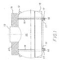
- Figure 1 is a liquid or liquefied gas container 10 for an underground, so-called earth-covered installation shown in side view.
- This liquefied gas container 10 are for installation under an earth cover 14 provided.
- the LPG container is for installation 10 with paired saddle feet 11 provided, which rest on a base plate 16.
- the LPG container 10 is schematic with a provided entry dome 13 provided by the Earth cover 14 is passed. Via the entry dome 13 is the LPG container 10 from the earth's surface 20 accessible from. For transport from the container manufacturer up to its installation site 22 is the Liquid gas container 10 provided with eyebolts 12.
- the liquefied gas container 10 with extending on both sides in the longitudinal direction, foldable Anchor plates 15 provided.
- the anchor plates 15 are shown folded here and the liquid gas container 10 assigned in the area of its saddle feet 11.
- the anchor plates 15 are at hinge points 17 on the Base plate 16 hinged.
- the liquid gas container 10 is with its saddle feet 11 connected to the base plate 16, preferably welded.
- Lashing straps are an additional safeguard 18 placed over the container surface 19.
- the lashing straps 18 are preferably connected to the saddle feet 11 and, as FIG. 1 shows, preferably arranged in pairs. They are made of a rot-proof material.
- the anchor plates 15 After installing the liquid gas container 10 on his Installation site 22, the anchor plates 15 in their Unfolded position 15a, as shown in FIG. 3 shows.
- the location 22 is usually one Pit that is installed after the installation of the LPG container 10 backfilled with soil 23. That around and over soil 23 heaped up on the liquid gas container 10 rests on the unfolded anchor plates 15 and serves as a counterweight for any buoyancy caused by entering Groundwater.
- the base plate 16 with laterally protruding stops 21 provided.
- the anchor plates 15 are after unfolding into their unfolded position 15a from the stops 21 held. With a possible buoyancy of the LPG containers 10 are intended to prevent the stops 21, that the anchor plates 15 laterally from the ground 23 can be drawn.
Landscapes
- Engineering & Computer Science (AREA)
- General Engineering & Computer Science (AREA)
- Mechanical Engineering (AREA)
- Life Sciences & Earth Sciences (AREA)
- Paleontology (AREA)
- Mining & Mineral Resources (AREA)
- General Life Sciences & Earth Sciences (AREA)
- Civil Engineering (AREA)
- Structural Engineering (AREA)
- Environmental & Geological Engineering (AREA)
- Hydrology & Water Resources (AREA)
- Filling Or Discharging Of Gas Storage Vessels (AREA)
- Supply Devices, Intensifiers, Converters, And Telemotors (AREA)
Abstract
Description
- Figur 1
- die Seitenansicht eines Flüssigkeitsbehälters, mit angeklappten Ankerplatten, Zurrgurten und mit schematisch angedeuteter Erdabdeckung, in Transportstellung;
- Figur 2
- die Vorderansicht eines Flüssigkeitsbehälters nach der Figur 1, mit angeklappten Ankerplatten;
- Figur 3
- die Vorderansicht eines Flüssigkeitsbehälters nach der Figur 1, mit ausgeklappten Ankerplatten.
- 10
- Flüssiggasbehälter
- 11
- Sattelfuß
- 12
- Transportöse
- 13
- Einstiegsdom
- 14
- Erdabdeckung
- 15
- Ankerplatte, angeklappt
- 15a
- Ausklappstellung der Ankerplatte
- 16
- Grundplatte
- 17
- Gelenkpunkt
- 18
- Zurrgurt
- 19
- Behälteroberfläche
- 20
- Erdoberfläche
- 21
- Anschlag
- 22
- Aufstellungsort
- 23
- Erdreich
Claims (10)
- Flüssiggasbehälteranlage, bestehend aus einem Flüssiggasbehälter zur unterirdischen Lagerung von Flüssiggas, mit Sattelfüßen zur Aufstellung, dadurch gekennzeichnet, dass dem Flüssiggasbehälter (10) beiderseits seitlich längsverlaufende Ankerplatten (15) zugeordnet sind.
- Flüssiggasbehälteranlage nach dem Anspruch 1, dadurch gekennzeichnet, dass die Ankerplatten (15) seitlich ausklappbar befestigt sind.
- Flüssiggasbehälteranlage nach den Ansprüchen 1 und 2, dadurch gekennzeichnet, dass die Ankerplatten (15) in Gelenkpunkten (17) ausklappbar sind.
- Flüssiggasbehälteranlage nach den Ansprüchen 1 bis 3, dadurch gekennzeichnet, dass die Gelenkpunkte (17) einer den Flüssiggasbehälter (10) tragenden Grundplatte (16) zugeordnet sind.
- Flüssiggasbehälteranlage nach den Ansprüchen 1 bis 4, dadurch gekennzeichnet, dass der Flüssiggasbehälter (10) auf Sattelfüßen (11) aufgestellt ist und die Sattelfüße (11) mit der Grundplatte (16) verbunden sind.
- Flüssiggasbehälteranlage nach den Ansprüchen 1 und 5, dadurch gekennzeichnet, dass die Sattelfüße (11) mit der Grundplatte (16) verschweißt sind.
- Flüssiggasbehälteranlage nach den Ansprüchen 1 bis 6, dadurch gekennzeichnet, dass der Flüssiggasbehälter (10) durch über seine Behälteroberfläche (19) verlaufende, aus einem verrottungsfesten Material bestehende Zurrgurte (18) mit der Grundplatte (16) verbunden ist.
- Flüssiggasbehälteranlage nach den Ansprüchen 1 bis 7, dadurch gekennzeichnet, dass die ausklappbaren Ankerplatten (15) in ihrer Länge etwa der Länge des einzulagernden Flüssiggasbehälters (10) und in ihrer Breite ca. einem Drittel des Behälterdurchmessers entsprechen.
- Flüssiggasbehälteranlage nach den Ansprüchen 1 bis 8, dadurch gekennzeichnet, dass die ausklappbaren Ankerplatten (15) aus Stahlblech bestehen.
- Flüssiggasbehälteranlage nach den Ansprüchen 1 bis 9, dadurch gekennzeichnet, dass die ausklappbaren Ankerplatten (15) mit Anschlägen (21) gegen die Grundplatte (16) abgestützt sind.
Applications Claiming Priority (2)
| Application Number | Priority Date | Filing Date | Title |
|---|---|---|---|
| DE20219993 | 2002-12-27 | ||
| DE20219993U | 2002-12-27 |
Publications (2)
| Publication Number | Publication Date |
|---|---|
| EP1433722A1 true EP1433722A1 (de) | 2004-06-30 |
| EP1433722B1 EP1433722B1 (de) | 2006-09-13 |
Family
ID=27798422
Family Applications (1)
| Application Number | Title | Priority Date | Filing Date |
|---|---|---|---|
| EP03012977A Expired - Lifetime EP1433722B1 (de) | 2002-12-27 | 2003-06-07 | Auftriebssicherung für erdgedeckt aufgestellte Flüssiggasbehälter |
Country Status (4)
| Country | Link |
|---|---|
| EP (1) | EP1433722B1 (de) |
| AT (1) | ATE339374T1 (de) |
| DE (2) | DE20307687U1 (de) |
| NO (1) | NO326006B1 (de) |
Cited By (2)
| Publication number | Priority date | Publication date | Assignee | Title |
|---|---|---|---|---|
| DE102018125171B3 (de) | 2018-10-11 | 2019-08-08 | SKG Umwelttechnik GmbH & Co. KG | Auftriebssicherung für einen erdgedeckt aufgestellten Behälter sowie erdgedeckt aufzustellender Behälter mit einer solchen Auftriebssicherung |
| EP3636985A1 (de) | 2018-10-11 | 2020-04-15 | SKG Umwelttechnik GmbH & Co. KG | Auftriebssicherung für einen erdgedeckt aufgestellten behälter sowie erdgedeckt aufzustellender behälter mit einer solchen auftriebssicherung |
Families Citing this family (3)
| Publication number | Priority date | Publication date | Assignee | Title |
|---|---|---|---|---|
| DE202013100382U1 (de) | 2013-01-28 | 2013-02-07 | TIS Transport Installation Service GmbH | Flüssiggasbehälteranlage und Auftriebssicherungsvorrichtung dafür |
| IT201700050764A1 (it) * | 2017-05-10 | 2018-11-10 | NoForm Srl | Metodo e sistema di ancoraggio a terra per un serbatoio di fermentazione/stoccaggio. |
| CN108978701A (zh) * | 2018-06-28 | 2018-12-11 | 武汉冶钢结构有限责任公司 | 用于覆土式储罐的支撑系统及其施工方法 |
Citations (3)
| Publication number | Priority date | Publication date | Assignee | Title |
|---|---|---|---|---|
| EP0758617A1 (de) * | 1995-08-16 | 1997-02-19 | Société Metallurgique Liotard Frères, Société Anonyme | Dem hydrostatischen Auftrieb widerstehender, unterirdischer Tank |
| FR2763050A1 (fr) * | 1997-05-09 | 1998-11-13 | Pierre Deschamps | Dispositif de protection d'une structure enterree, notamment d'une cuve |
| US6345933B1 (en) * | 2000-04-03 | 2002-02-12 | Clawson Tank Company | Tank with backfill deflectors |
-
2003
- 2003-05-16 DE DE20307687U patent/DE20307687U1/de not_active Expired - Lifetime
- 2003-06-07 DE DE50305022T patent/DE50305022D1/de not_active Expired - Lifetime
- 2003-06-07 EP EP03012977A patent/EP1433722B1/de not_active Expired - Lifetime
- 2003-06-07 AT AT03012977T patent/ATE339374T1/de active
- 2003-07-29 NO NO20033381A patent/NO326006B1/no not_active IP Right Cessation
Patent Citations (3)
| Publication number | Priority date | Publication date | Assignee | Title |
|---|---|---|---|---|
| EP0758617A1 (de) * | 1995-08-16 | 1997-02-19 | Société Metallurgique Liotard Frères, Société Anonyme | Dem hydrostatischen Auftrieb widerstehender, unterirdischer Tank |
| FR2763050A1 (fr) * | 1997-05-09 | 1998-11-13 | Pierre Deschamps | Dispositif de protection d'une structure enterree, notamment d'une cuve |
| US6345933B1 (en) * | 2000-04-03 | 2002-02-12 | Clawson Tank Company | Tank with backfill deflectors |
Cited By (2)
| Publication number | Priority date | Publication date | Assignee | Title |
|---|---|---|---|---|
| DE102018125171B3 (de) | 2018-10-11 | 2019-08-08 | SKG Umwelttechnik GmbH & Co. KG | Auftriebssicherung für einen erdgedeckt aufgestellten Behälter sowie erdgedeckt aufzustellender Behälter mit einer solchen Auftriebssicherung |
| EP3636985A1 (de) | 2018-10-11 | 2020-04-15 | SKG Umwelttechnik GmbH & Co. KG | Auftriebssicherung für einen erdgedeckt aufgestellten behälter sowie erdgedeckt aufzustellender behälter mit einer solchen auftriebssicherung |
Also Published As
| Publication number | Publication date |
|---|---|
| NO20033381L (no) | 2004-06-28 |
| DE20307687U1 (de) | 2003-08-28 |
| NO20033381D0 (no) | 2003-07-29 |
| DE50305022D1 (de) | 2006-10-26 |
| EP1433722B1 (de) | 2006-09-13 |
| ATE339374T1 (de) | 2006-10-15 |
| NO326006B1 (no) | 2008-09-01 |
Similar Documents
| Publication | Publication Date | Title |
|---|---|---|
| EP0954644B1 (de) | Mobile vorrichtung zum schutz gegen hochwasser | |
| LU100365B1 (de) | Absperrvorrichtung zum Verhindern der Durchfahrt von Landfahrzeugen | |
| DE102010026117B4 (de) | Offshore-Anlage, insbesondere Windkraftanlage | |
| US11565876B1 (en) | Surface mounted secondary containment system | |
| DE2700624A1 (de) | Dockanlage | |
| DE102016011572A1 (de) | Bauwerk zur Errichtung an Gewässeroberflächen und Verfahren zu seiner Errichtung | |
| DE69318730T2 (de) | Tankstelle und verfahren zu deren zusammenbau | |
| EP1433722B1 (de) | Auftriebssicherung für erdgedeckt aufgestellte Flüssiggasbehälter | |
| DE1243375B (de) | In das Erdreich einzubettender Lagerbehaelter | |
| DE2605392A1 (de) | Hochsee- bohr- und -foerderinsel | |
| WO1988008822A1 (fr) | Cylindre a gaz comprimes comportant un dispositif d'essai, de stockage et de surveillance de gaz comprimes comme l'ammoniac, le propane et similaire | |
| EP3448783B1 (de) | Vorrichtung zur verhinderung des aufschwimmens von tanks in schutzbauwerken im hochwasserfall | |
| DE10323556A1 (de) | Verfahren, Vorrichtung und Anordnung zum Auffangen von Unterwasser austretenden Medien | |
| DE29718815U1 (de) | Vorrichtung zur Absturzsicherung | |
| DE102007027690B3 (de) | Ölbohrinsel-Sprengung | |
| DE3543321C2 (de) | ||
| Johnson | The Davis Island Lock and Dam, 1870-1922 | |
| DE20015044U1 (de) | Tankstelle für Wasserfahrzeuge | |
| DE29511458U1 (de) | Hochwasserschutzwand | |
| DE2949063A1 (de) | Im wasser stehende anlagenplattform | |
| Percher et al. | Seismic Retrofit of an Existing MOT Using Float-In Construction for Rapid Turnaround | |
| DE202006004914U1 (de) | Behälter für wassergefährdende Flüssigkeiten in Überschwemmungsgebieten | |
| DE202010017856U1 (de) | Offshore-Anlage, insbesondere Windkraftanlage | |
| DE2060730C3 (de) | Stützbein für kugelförmige Behälter | |
| DE202006011308U1 (de) | Hochwasserschutzwand |
Legal Events
| Date | Code | Title | Description |
|---|---|---|---|
| PUAI | Public reference made under article 153(3) epc to a published international application that has entered the european phase |
Free format text: ORIGINAL CODE: 0009012 |
|
| AK | Designated contracting states |
Kind code of ref document: A1 Designated state(s): AT BE BG CH CY CZ DE DK EE ES FI FR GB GR HU IE IT LI LU MC NL PT RO SE SI SK TR |
|
| AX | Request for extension of the european patent |
Extension state: AL LT LV MK |
|
| 17P | Request for examination filed |
Effective date: 20041124 |
|
| 17Q | First examination report despatched |
Effective date: 20050117 |
|
| AKX | Designation fees paid |
Designated state(s): AT BE BG CH CY CZ DE DK EE ES FI FR GB GR HU IE IT LI LU MC NL PT RO SE SI SK TR |
|
| RAP1 | Party data changed (applicant data changed or rights of an application transferred) |
Owner name: STAHL- & INDUSTRIE- TOOLS VERTRIEBS GMBH |
|
| GRAP | Despatch of communication of intention to grant a patent |
Free format text: ORIGINAL CODE: EPIDOSNIGR1 |
|
| GRAS | Grant fee paid |
Free format text: ORIGINAL CODE: EPIDOSNIGR3 |
|
| GRAA | (expected) grant |
Free format text: ORIGINAL CODE: 0009210 |
|
| AK | Designated contracting states |
Kind code of ref document: B1 Designated state(s): AT BE BG CH CY CZ DE DK EE ES FI FR GB GR HU IE IT LI LU MC NL PT RO SE SI SK TR |
|
| PG25 | Lapsed in a contracting state [announced via postgrant information from national office to epo] |
Ref country code: SK Free format text: LAPSE BECAUSE OF FAILURE TO SUBMIT A TRANSLATION OF THE DESCRIPTION OR TO PAY THE FEE WITHIN THE PRESCRIBED TIME-LIMIT Effective date: 20060913 Ref country code: IT Free format text: LAPSE BECAUSE OF FAILURE TO SUBMIT A TRANSLATION OF THE DESCRIPTION OR TO PAY THE FEE WITHIN THE PRESCRIBED TIME-LIMIT;WARNING: LAPSES OF ITALIAN PATENTS WITH EFFECTIVE DATE BEFORE 2007 MAY HAVE OCCURRED AT ANY TIME BEFORE 2007. THE CORRECT EFFECTIVE DATE MAY BE DIFFERENT FROM THE ONE RECORDED. Effective date: 20060913 Ref country code: SI Free format text: LAPSE BECAUSE OF FAILURE TO SUBMIT A TRANSLATION OF THE DESCRIPTION OR TO PAY THE FEE WITHIN THE PRESCRIBED TIME-LIMIT Effective date: 20060913 Ref country code: NL Free format text: LAPSE BECAUSE OF FAILURE TO SUBMIT A TRANSLATION OF THE DESCRIPTION OR TO PAY THE FEE WITHIN THE PRESCRIBED TIME-LIMIT Effective date: 20060913 Ref country code: CZ Free format text: LAPSE BECAUSE OF FAILURE TO SUBMIT A TRANSLATION OF THE DESCRIPTION OR TO PAY THE FEE WITHIN THE PRESCRIBED TIME-LIMIT Effective date: 20060913 Ref country code: RO Free format text: LAPSE BECAUSE OF FAILURE TO SUBMIT A TRANSLATION OF THE DESCRIPTION OR TO PAY THE FEE WITHIN THE PRESCRIBED TIME-LIMIT Effective date: 20060913 |
|
| REG | Reference to a national code |
Ref country code: GB Ref legal event code: FG4D Free format text: NOT ENGLISH |
|
| REG | Reference to a national code |
Ref country code: CH Ref legal event code: EP |
|
| REG | Reference to a national code |
Ref country code: IE Ref legal event code: FG4D Free format text: LANGUAGE OF EP DOCUMENT: GERMAN |
|
| REF | Corresponds to: |
Ref document number: 50305022 Country of ref document: DE Date of ref document: 20061026 Kind code of ref document: P |
|
| PG25 | Lapsed in a contracting state [announced via postgrant information from national office to epo] |
Ref country code: BG Free format text: LAPSE BECAUSE OF FAILURE TO SUBMIT A TRANSLATION OF THE DESCRIPTION OR TO PAY THE FEE WITHIN THE PRESCRIBED TIME-LIMIT Effective date: 20061213 Ref country code: DK Free format text: LAPSE BECAUSE OF FAILURE TO SUBMIT A TRANSLATION OF THE DESCRIPTION OR TO PAY THE FEE WITHIN THE PRESCRIBED TIME-LIMIT Effective date: 20061213 |
|
| PG25 | Lapsed in a contracting state [announced via postgrant information from national office to epo] |
Ref country code: ES Free format text: LAPSE BECAUSE OF FAILURE TO SUBMIT A TRANSLATION OF THE DESCRIPTION OR TO PAY THE FEE WITHIN THE PRESCRIBED TIME-LIMIT Effective date: 20061224 |
|
| REG | Reference to a national code |
Ref country code: SE Ref legal event code: TRGR |
|
| REG | Reference to a national code |
Ref country code: CH Ref legal event code: NV Representative=s name: KELLER & PARTNER PATENTANWAELTE AG |
|
| GBT | Gb: translation of ep patent filed (gb section 77(6)(a)/1977) |
Effective date: 20070117 |
|
| PG25 | Lapsed in a contracting state [announced via postgrant information from national office to epo] |
Ref country code: PT Free format text: LAPSE BECAUSE OF FAILURE TO SUBMIT A TRANSLATION OF THE DESCRIPTION OR TO PAY THE FEE WITHIN THE PRESCRIBED TIME-LIMIT Effective date: 20070226 |
|
| NLV1 | Nl: lapsed or annulled due to failure to fulfill the requirements of art. 29p and 29m of the patents act | ||
| ET | Fr: translation filed | ||
| PLBE | No opposition filed within time limit |
Free format text: ORIGINAL CODE: 0009261 |
|
| STAA | Information on the status of an ep patent application or granted ep patent |
Free format text: STATUS: NO OPPOSITION FILED WITHIN TIME LIMIT |
|
| 26N | No opposition filed |
Effective date: 20070614 |
|
| PG25 | Lapsed in a contracting state [announced via postgrant information from national office to epo] |
Ref country code: MC Free format text: LAPSE BECAUSE OF NON-PAYMENT OF DUE FEES Effective date: 20070630 |
|
| PG25 | Lapsed in a contracting state [announced via postgrant information from national office to epo] |
Ref country code: GR Free format text: LAPSE BECAUSE OF FAILURE TO SUBMIT A TRANSLATION OF THE DESCRIPTION OR TO PAY THE FEE WITHIN THE PRESCRIBED TIME-LIMIT Effective date: 20061214 |
|
| PG25 | Lapsed in a contracting state [announced via postgrant information from national office to epo] |
Ref country code: EE Free format text: LAPSE BECAUSE OF FAILURE TO SUBMIT A TRANSLATION OF THE DESCRIPTION OR TO PAY THE FEE WITHIN THE PRESCRIBED TIME-LIMIT Effective date: 20060913 |
|
| PGFP | Annual fee paid to national office [announced via postgrant information from national office to epo] |
Ref country code: IE Payment date: 20090618 Year of fee payment: 7 |
|
| PG25 | Lapsed in a contracting state [announced via postgrant information from national office to epo] |
Ref country code: CY Free format text: LAPSE BECAUSE OF FAILURE TO SUBMIT A TRANSLATION OF THE DESCRIPTION OR TO PAY THE FEE WITHIN THE PRESCRIBED TIME-LIMIT Effective date: 20060913 Ref country code: LU Free format text: LAPSE BECAUSE OF NON-PAYMENT OF DUE FEES Effective date: 20070607 |
|
| PGFP | Annual fee paid to national office [announced via postgrant information from national office to epo] |
Ref country code: FI Payment date: 20090624 Year of fee payment: 7 Ref country code: SE Payment date: 20090623 Year of fee payment: 7 |
|
| PG25 | Lapsed in a contracting state [announced via postgrant information from national office to epo] |
Ref country code: TR Free format text: LAPSE BECAUSE OF FAILURE TO SUBMIT A TRANSLATION OF THE DESCRIPTION OR TO PAY THE FEE WITHIN THE PRESCRIBED TIME-LIMIT Effective date: 20060913 Ref country code: HU Free format text: LAPSE BECAUSE OF FAILURE TO SUBMIT A TRANSLATION OF THE DESCRIPTION OR TO PAY THE FEE WITHIN THE PRESCRIBED TIME-LIMIT Effective date: 20070314 |
|
| PGFP | Annual fee paid to national office [announced via postgrant information from national office to epo] |
Ref country code: BE Payment date: 20090623 Year of fee payment: 7 |
|
| PGFP | Annual fee paid to national office [announced via postgrant information from national office to epo] |
Ref country code: FR Payment date: 20090618 Year of fee payment: 7 |
|
| PGFP | Annual fee paid to national office [announced via postgrant information from national office to epo] |
Ref country code: GB Payment date: 20090623 Year of fee payment: 7 |
|
| BERE | Be: lapsed |
Owner name: STAHL- & INDUSTRIE- TOOLS VERTRIEBS GMBH Effective date: 20100630 |
|
| PG25 | Lapsed in a contracting state [announced via postgrant information from national office to epo] |
Ref country code: FI Free format text: LAPSE BECAUSE OF NON-PAYMENT OF DUE FEES Effective date: 20100607 |
|
| EUG | Se: european patent has lapsed | ||
| GBPC | Gb: european patent ceased through non-payment of renewal fee |
Effective date: 20100607 |
|
| REG | Reference to a national code |
Ref country code: FR Ref legal event code: ST Effective date: 20110228 |
|
| PG25 | Lapsed in a contracting state [announced via postgrant information from national office to epo] |
Ref country code: IE Free format text: LAPSE BECAUSE OF NON-PAYMENT OF DUE FEES Effective date: 20100607 |
|
| PG25 | Lapsed in a contracting state [announced via postgrant information from national office to epo] |
Ref country code: FR Free format text: LAPSE BECAUSE OF NON-PAYMENT OF DUE FEES Effective date: 20100630 |
|
| PG25 | Lapsed in a contracting state [announced via postgrant information from national office to epo] |
Ref country code: BE Free format text: LAPSE BECAUSE OF NON-PAYMENT OF DUE FEES Effective date: 20100630 |
|
| PG25 | Lapsed in a contracting state [announced via postgrant information from national office to epo] |
Ref country code: GB Free format text: LAPSE BECAUSE OF NON-PAYMENT OF DUE FEES Effective date: 20100607 |
|
| PG25 | Lapsed in a contracting state [announced via postgrant information from national office to epo] |
Ref country code: SE Free format text: LAPSE BECAUSE OF NON-PAYMENT OF DUE FEES Effective date: 20100608 |
|
| REG | Reference to a national code |
Ref country code: CH Ref legal event code: PCAR Free format text: NEW ADDRESS: EIGERSTRASSE 2 POSTFACH, 3000 BERN 14 (CH) |
|
| REG | Reference to a national code |
Ref country code: DE Ref legal event code: R082 Ref document number: 50305022 Country of ref document: DE Representative=s name: TERGAU & WALKENHORST PATENTANWAELTE PARTGMBB, DE Ref country code: DE Ref legal event code: R081 Ref document number: 50305022 Country of ref document: DE Owner name: BARTH, MICHEL, DE Free format text: FORMER OWNER: STAHL- & INDUSTRIE- TOOLS VERTRIEBS GMBH, ROHRMOOS, AT |
|
| REG | Reference to a national code |
Ref country code: CH Ref legal event code: PUE Owner name: MICHEL BARTH, DE Free format text: FORMER OWNER: STAHL- AND INDUSTRIE- TOOLS VERTRIEBS GMBH, AT |
|
| PGFP | Annual fee paid to national office [announced via postgrant information from national office to epo] |
Ref country code: DE Payment date: 20200629 Year of fee payment: 18 |
|
| REG | Reference to a national code |
Ref country code: AT Ref legal event code: PC Ref document number: 339374 Country of ref document: AT Kind code of ref document: T Owner name: MICHEL BARTH, DE Effective date: 20200623 |
|
| PGFP | Annual fee paid to national office [announced via postgrant information from national office to epo] |
Ref country code: AT Payment date: 20200618 Year of fee payment: 18 |
|
| REG | Reference to a national code |
Ref country code: CH Ref legal event code: PFA Owner name: MICHEL BARTH, DE Free format text: FORMER OWNER: MICHEL BARTH, DE |
|
| PGFP | Annual fee paid to national office [announced via postgrant information from national office to epo] |
Ref country code: CH Payment date: 20200630 Year of fee payment: 18 |
|
| REG | Reference to a national code |
Ref country code: DE Ref legal event code: R119 Ref document number: 50305022 Country of ref document: DE |
|
| REG | Reference to a national code |
Ref country code: CH Ref legal event code: PL |
|
| REG | Reference to a national code |
Ref country code: AT Ref legal event code: MM01 Ref document number: 339374 Country of ref document: AT Kind code of ref document: T Effective date: 20210607 |
|
| PG25 | Lapsed in a contracting state [announced via postgrant information from national office to epo] |
Ref country code: LI Free format text: LAPSE BECAUSE OF NON-PAYMENT OF DUE FEES Effective date: 20210630 Ref country code: DE Free format text: LAPSE BECAUSE OF NON-PAYMENT OF DUE FEES Effective date: 20220101 Ref country code: CH Free format text: LAPSE BECAUSE OF NON-PAYMENT OF DUE FEES Effective date: 20210630 Ref country code: AT Free format text: LAPSE BECAUSE OF NON-PAYMENT OF DUE FEES Effective date: 20210607 |