EP1433713B1 - Package comprising a sleeve with at least a container retaining element - Google Patents
Package comprising a sleeve with at least a container retaining element Download PDFInfo
- Publication number
- EP1433713B1 EP1433713B1 EP03292877A EP03292877A EP1433713B1 EP 1433713 B1 EP1433713 B1 EP 1433713B1 EP 03292877 A EP03292877 A EP 03292877A EP 03292877 A EP03292877 A EP 03292877A EP 1433713 B1 EP1433713 B1 EP 1433713B1
- Authority
- EP
- European Patent Office
- Prior art keywords
- containers
- flap
- lower wall
- packaging
- wall
- Prior art date
- Legal status (The legal status is an assumption and is not a legal conclusion. Google has not performed a legal analysis and makes no representation as to the accuracy of the status listed.)
- Expired - Lifetime
Links
- 238000004806 packaging method and process Methods 0.000 claims description 24
- 239000000853 adhesive Substances 0.000 abstract 1
- 230000001070 adhesive effect Effects 0.000 abstract 1
- 230000014759 maintenance of location Effects 0.000 description 7
- 235000013618 yogurt Nutrition 0.000 description 4
- 230000015572 biosynthetic process Effects 0.000 description 3
- 239000011229 interlayer Substances 0.000 description 2
- 125000006850 spacer group Chemical group 0.000 description 2
- 238000004026 adhesive bonding Methods 0.000 description 1
- 238000005452 bending Methods 0.000 description 1
- 210000004027 cell Anatomy 0.000 description 1
- 230000001419 dependent effect Effects 0.000 description 1
- 238000012423 maintenance Methods 0.000 description 1
- 238000004519 manufacturing process Methods 0.000 description 1
- 238000003856 thermoforming Methods 0.000 description 1
Images

Classifications
-
- B—PERFORMING OPERATIONS; TRANSPORTING
- B65—CONVEYING; PACKING; STORING; HANDLING THIN OR FILAMENTARY MATERIAL
- B65D—CONTAINERS FOR STORAGE OR TRANSPORT OF ARTICLES OR MATERIALS, e.g. BAGS, BARRELS, BOTTLES, BOXES, CANS, CARTONS, CRATES, DRUMS, JARS, TANKS, HOPPERS, FORWARDING CONTAINERS; ACCESSORIES, CLOSURES, OR FITTINGS THEREFOR; PACKAGING ELEMENTS; PACKAGES
- B65D71/00—Bundles of articles held together by packaging elements for convenience of storage or transport, e.g. portable segregating carrier for plural receptacles such as beer cans or pop bottles; Bales of material
- B65D71/06—Packaging elements holding or encircling completely or almost completely the bundle of articles, e.g. wrappers
- B65D71/12—Packaging elements holding or encircling completely or almost completely the bundle of articles, e.g. wrappers the packaging elements, e.g. wrappers being formed by folding a single blank
- B65D71/14—Packaging elements holding or encircling completely or almost completely the bundle of articles, e.g. wrappers the packaging elements, e.g. wrappers being formed by folding a single blank having a tubular shape, e.g. tubular wrappers without end walls
- B65D71/16—Packaging elements holding or encircling completely or almost completely the bundle of articles, e.g. wrappers the packaging elements, e.g. wrappers being formed by folding a single blank having a tubular shape, e.g. tubular wrappers without end walls with article-locating elements
-
- B—PERFORMING OPERATIONS; TRANSPORTING
- B65—CONVEYING; PACKING; STORING; HANDLING THIN OR FILAMENTARY MATERIAL
- B65D—CONTAINERS FOR STORAGE OR TRANSPORT OF ARTICLES OR MATERIALS, e.g. BAGS, BARRELS, BOTTLES, BOXES, CANS, CARTONS, CRATES, DRUMS, JARS, TANKS, HOPPERS, FORWARDING CONTAINERS; ACCESSORIES, CLOSURES, OR FITTINGS THEREFOR; PACKAGING ELEMENTS; PACKAGES
- B65D2571/00—Bundles of articles held together by packaging elements for convenience of storage or transport, e.g. portable segregating carrier for plural receptacles such as beer cans, pop bottles; Bales of material
- B65D2571/00123—Bundling wrappers or trays
- B65D2571/00648—Elements used to form the wrapper
- B65D2571/00654—Blanks
- B65D2571/0066—Blanks formed from one single sheet
-
- B—PERFORMING OPERATIONS; TRANSPORTING
- B65—CONVEYING; PACKING; STORING; HANDLING THIN OR FILAMENTARY MATERIAL
- B65D—CONTAINERS FOR STORAGE OR TRANSPORT OF ARTICLES OR MATERIALS, e.g. BAGS, BARRELS, BOTTLES, BOXES, CANS, CARTONS, CRATES, DRUMS, JARS, TANKS, HOPPERS, FORWARDING CONTAINERS; ACCESSORIES, CLOSURES, OR FITTINGS THEREFOR; PACKAGING ELEMENTS; PACKAGES
- B65D2571/00—Bundles of articles held together by packaging elements for convenience of storage or transport, e.g. portable segregating carrier for plural receptacles such as beer cans, pop bottles; Bales of material
- B65D2571/00123—Bundling wrappers or trays
- B65D2571/00709—Shape of the formed wrapper, i.e. shape of each formed element if the wrapper is made from more than one element
- B65D2571/00716—Shape of the formed wrapper, i.e. shape of each formed element if the wrapper is made from more than one element tubular without end walls
-
- B—PERFORMING OPERATIONS; TRANSPORTING
- B65—CONVEYING; PACKING; STORING; HANDLING THIN OR FILAMENTARY MATERIAL
- B65D—CONTAINERS FOR STORAGE OR TRANSPORT OF ARTICLES OR MATERIALS, e.g. BAGS, BARRELS, BOTTLES, BOXES, CANS, CARTONS, CRATES, DRUMS, JARS, TANKS, HOPPERS, FORWARDING CONTAINERS; ACCESSORIES, CLOSURES, OR FITTINGS THEREFOR; PACKAGING ELEMENTS; PACKAGES
- B65D2571/00—Bundles of articles held together by packaging elements for convenience of storage or transport, e.g. portable segregating carrier for plural receptacles such as beer cans, pop bottles; Bales of material
- B65D2571/00123—Bundling wrappers or trays
- B65D2571/00833—Other details of wrappers
- B65D2571/0087—Special features for machine processing, e.g. gripper apertures
Definitions
- the present invention relates to a package for packaging a group of at least two containers, the package being of the type comprising at least one longitudinally extending sheath and comprising an upper wall, a lower wall, two side walls connecting the lower walls and upper, and at least one container holding member, the holding member protruding from the bottom wall to be disposed between containers, the holding member comprising a shutter cut in the bottom wall and folded around a line bending, the flap being cut into the bottom wall of a first side of the fold line.
- the invention applies, for example, to the packaging of jars of yoghurt or compote.
- the sheath is made of cardboard and the bottom wall is formed of two half-walls fixed rune to another.
- the holding member is a beam which extends longitudinally between two rows of pots and which is formed from a shutter cut into the edge of a first of the lower half-walls.
- the flap is folded relative to the first half-bottom wall around a fold line and is attached to the other lower half-wall.
- the beam is located on the same side of the fold line as the one where the shutter was cut.
- Such a holding element structure requires using a lot of cardboard, and more than if the bottom wall was made in one piece.
- DE-39 28 076 also discloses a package comprising a sleeve with a holding beam which requires the use of a large amount of cardboard.
- An object of the invention is to solve this problem by providing a package of the aforementioned type in which the structure of the holding member can reduce the cost of packaging.
- the subject of the invention is a package according to claim 1.
- the package may comprise one or more of the features of the dependent claims.
- the invention also relates to an assembly according to claim 11.
- the invention further relates to a blank according to claim 12.
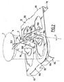
- FIG. 1 represents a set 1 comprising a group 2 of eight jars of yogurt 3 and a package 4.
- the pots 3 are identical, arranged vertically and have for example a generally frustoconical shape converging downwards. As illustrated for example in Figure 2, the pots 3 each have at their upper open end an annular rim 6 and a circular seal 7 closing this open end.
- pots 3 have been shown in phantom in Figures 1 and 2 and some pots 3 have not been shown for more visibility.
- the pots 3 are arranged in two superimposed levels, namely a lower level of four pots 3, and a top level of four pots 3.
- the pots 3 of the upper level each surmount a pot 3 of the lower level.
- the four pots 3 are regularly arranged in two rows 10 extending in a longitudinal direction L of the package 4.
- the package 4 comprises an outer sleeve 11 which externally envelops the group 2, and an insert 12 disposed between the lower level and the upper level of pots 3.
- the fold line 17 is interrupted by two cuts 35 formed in the right side wall 16. These cutouts 35 delimit two flanges 36 extending the upper wall 15 and two clearances 37 substantially rectangular.
- Two disc-shaped openings 38 are formed in the lower region 23 of the right-hand side wall 16.
- Two oblong slots 40 are formed substantially in the center of the bottom wall 25, facing the openings 38.
- Two cutouts 41 are formed in the lower region 31 of the left-hand lateral wall 27 and in the lower wall 25. These cut-outs 41 each comprise a section 42 in the shape of an arc in the region 31.
- the sections 42 have, for example, a corresponding shape. at the contour of the openings 38.
- the sections 42 are each extended by two curved end sections 44 which extend in the bottom wall 25 towards the slots 40.
- the cutouts 41 delimit two flaps 46 which are connected to the lower wall 25 by fold lines 48 which are each between the ends of the two sections 44 of the corresponding cut 41.
- Each flap 46 is thus cut on the left side (at the top in FIG. 3) of the corresponding fold line 48.
- Each flap 46 comprises from the fold line 48 corresponding four successive panels 50, 52, 54, 56 separated by longitudinal fold lines 58.
- the panel 56 farthest from the fold line 48 hereinafter referred to as an end panel, has a disk sector shape.
- the fold line 33 is interrupted by two cutouts 60 in U which delimit flanges 62 extending the fastening flap 32.
- the flaps 46 are folded from the side to the left of the fold lines 48 to the right side thereof.
- the end panels 56 are glued to the bottom wall 25 to the right of the fold lines 48 and beyond the oblong slots 40.
- the panels 50, 52, 54 and 56 are then folded relative to each other around the fold lines 58 substantially at right angles, as shown in FIG.
- Each flap 46 thus forms a beam 64 of substantially square section. Alternatively, this section may be rectangular.
- the beam 64 is located to the right of the fold line 48 corresponding, while the flap 46 has been cut to the left of this fold line 48.
- the side walls 16 and 27 are bent upwards with respect to the bottom wall 25.
- the formation of the beams 64 has cleared in the lower region 31 of the left lateral wall 27 two openings 38 of shape corresponding to that of the openings 38 formed in the lower region 23 of the right side wall 16.
- the lower ends of the lower pots 3 are engaged in the openings 38 of the right lateral wall 16 and of the left lateral wall 27, thus ensuring longitudinal retention of the lower pots 3 with respect to the sleeve 11.
- the two beams 64 project upward from the bottom wall 25 between the right and left rows of the lower pots 3.
- the front beam 64 in FIG. 1 is disposed between the lower front pots 3, and the rear beam 64 is disposed between the rear lower pots 3.
- the beams 64 hold the lower pots 3 transversely and lay them down in particular at the bottom of the openings 38.
- the lower right pots 3 each rest on the end panel 56 of the corresponding beam 64.
- the upper flap 32 is folded relative to the left side wall 27 and glued under the upper wall 15 which is itself folded with respect to the right side wall 16.
- Two oblong slots 92 are formed in the center of the central wall 74 one behind the other.
- a female tab 94 is cut in the central wall 74 to the left of each slot 92 and a male tab 96 is cut in the central wall 74 to the right of each slot 92.
- the female tabs 94 and the male tabs 96 have substantially U-shaped inverted shapes. They are connected to the remainder of the central wall 74 by longitudinal fold lines 98 arranged at the ends of the branches of the tabs 94 and 96.
- a notch 100 in the form of a disk sector is provided in each female lug 94.
- Each male lug 96 is extended by a tongue 102 in the form of a half-disk.
- the insert 12 is disposed inside the sheath 11 and the central wall 74 covers the lower pots 3 while the upper pots 3 rest on the central wall 74.
- the upper flanges 6 of the lower pots 3 are each engaged in an opening 104 thus ensuring longitudinal retention of the lower pots 3 with respect to the insert 12.
- the tabs 94 and 96 bordering each slot 92 are folded toward each other above the central wall 74 to form a trestle retaining member 106.
- the tongue 102 of the male lug 96 is then engaged in the notch 100 of the female lug 94 thus ensuring the holding of the retaining element 106.
- the two retaining elements 106 thus formed are arranged one behind the other above the central wall 74, the front element 106 being disposed between the upper front pots 3 and the rear element 106 between the upper pots 3 back.
- the retaining elements 106 retain the upper pots 3 both longitudinally and transversely with respect to the insert 12.
- the beams 64 are first formed on the lower wall 25 of the sheath 11, then the lower pots 3 are placed on the bottom wall 25.
- the spacer 12 is then placed on the lower pots 3 after having formed the retaining elements 106 on the central wall 74.
- the upper pots 3 are then placed on the insert 12 and then the side walls 16 and 27 of the sheath 11 are folded to envelop the group 2 of pots 3.
- top wall 15 is fixed to the fastening flap 32 by gluing.
- the slots 40 and 92 provided in the blanks 13 and 72 make it easy to handle them by means of suction cups and thus to automate the production of the assembly 1.
- the flaps 46 are each cut on the same side of a fold line 48 and folded over the lower wall 25 on the other side of this fold line 48, the bottom wall 25 may be of reduced dimensions.
- the cost of the blank 13 and the packaging 4 is therefore particularly small.
- the structure of the beams 64 formed by the flaps 46, and in particular their section, gives them a high rigidity so that the size of the openings 38 can be reduced.
- the risks of tearing of the sleeve 11 are reduced and a light weight cardboard or recycled cardboard can be used to form the sleeve 11, which further reduces the cost.
- the panels 56 on which the lower right pots 3 rest, also contribute to the strength of the beams 64.
- the insert 12 interposed between the lower pots 3 and the upper pots 3 protects the lids of the lower pots 3.
- openings 104 form lower pot retention means 3 which, in combination with the retaining elements 106 of the upper pots 3, allow satisfactory maintenance of the pots 3 in the sheath 11.
- the self-supporting structure of the retainers 106 also reduces the basis weight of the carton used to form the insert 12 so that the overall cost of the package 4 can be reduced.
- the two side walls 16 and 27 are not cut or deteriorated to ensure the retention of the lower pots 3 relative to the upper pots 3.
- holding beams 64 and the retaining means 104 and 106 may have different shapes from those described above.
- Figure 5 shows a blank 13 to form a sheath 11 according to a second embodiment.
- This blank 13 differs from that of Figure 3 in that the side walls 16 and 27 are of smaller height and do not have a middle fold line. Thus, this blank 13 is intended to form a packaging package 4 of a group of pots 3 arranged in a single level. The package 4 therefore does not include tab 12.
- packaging pots 3 whose upper ends are interconnected, for example yogurt pots made by thermoforming a plastic plate.
- these principles can be used to package other types of containers than yoghurt pots.
Landscapes
- Engineering & Computer Science (AREA)
- Mechanical Engineering (AREA)
- Cartons (AREA)
- Packages (AREA)
Abstract
Description
La présente invention concerne un emballage pour conditionner un groupe d'au moins deux récipients, l'emballage étant du type comprenant au moins un fourreau s'étendant longitudinalement et comprenant une paroi supérieure, une paroi inférieure, deux parois latérales reliant les parois inférieure et supérieure, et au moins un élément de maintien des récipients, l'élément de maintien faisant saillie depuis la paroi inférieure pour être disposé entre des récipients, l'élément de maintien comprenant un volet découpé dans la paroi inférieure et plié autour d'une ligne de pliage, le volet étant découpé dans la paroi inférieure d'un premier côté de la ligne de pliage.The present invention relates to a package for packaging a group of at least two containers, the package being of the type comprising at least one longitudinally extending sheath and comprising an upper wall, a lower wall, two side walls connecting the lower walls and upper, and at least one container holding member, the holding member protruding from the bottom wall to be disposed between containers, the holding member comprising a shutter cut in the bottom wall and folded around a line bending, the flap being cut into the bottom wall of a first side of the fold line.
L'invention s'applique par exemple, au conditionnement de pots de yaourt ou de compote.The invention applies, for example, to the packaging of jars of yoghurt or compote.
On connaît un emballage du type précité du document EP-271 056.There is known a package of the aforementioned type of EP-271 056.
Le fourreau y est réalisé en carton et la paroi inférieure est formée de deux demi-parois fixées rune à l'autre. L'élément de maintien est une poutre qui s'étend longitudinalement entre deux rangées de pots et qui est formée à partir d'un volet découpé dans le bord d'une première des demi-parois inférieures. Pour former la poutre, le volet est plié par rapport à la première deml-paroi inférieure autour d'une ligne de pliage et est fixé à l'autre demi-paroi inférieure. Dans le fourreau, la poutre est située du même côté de la ligne de pliage que celui où le volet a été découpé.The sheath is made of cardboard and the bottom wall is formed of two half-walls fixed rune to another. The holding member is a beam which extends longitudinally between two rows of pots and which is formed from a shutter cut into the edge of a first of the lower half-walls. To form the beam, the flap is folded relative to the first half-bottom wall around a fold line and is attached to the other lower half-wall. In the sheath, the beam is located on the same side of the fold line as the one where the shutter was cut.
Une telle structure d'élément de maintien nécessite d'employer beaucoup de carton, et notamment plus que si la paroi inférieure était réalisée en une seule partie.Such a holding element structure requires using a lot of cardboard, and more than if the bottom wall was made in one piece.
Ainsi, le coût d'un tel emballage s'avère élevé.Thus, the cost of such packaging is high.
DE-39 28 076 décrit également un emballage comprenant un fourreau avec une poutre de maintien qui nécessite d'employer beaucoup de carton.DE-39 28 076 also discloses a package comprising a sleeve with a holding beam which requires the use of a large amount of cardboard.
Un but de l'invention est de résoudre ce problème en foumissant un emballage du type précité dans lequel la structure de l'élément de maintien permet de réduire le coût de l'emballage.An object of the invention is to solve this problem by providing a package of the aforementioned type in which the structure of the holding member can reduce the cost of packaging.
A cet effet, l'invention a pour objet un emballage selon la revendication 1.For this purpose, the subject of the invention is a package according to claim 1.
Selon des modes particuliers de réalisation, l'emballage peut comprendre l'une ou plusieurs des caractéristiques des revendications dépendantes.According to particular embodiments, the package may comprise one or more of the features of the dependent claims.
L'invention a également pour objet un ensemble selon la revendication 11.The invention also relates to an assembly according to
L'invention a en outre pour objet un flan selon la revendication 12.The invention further relates to a blank according to
L'invention sera mieux comprise à la lecture de la description qui va suivre, donnée uniquement à titre d'exemple, et faite en se référant aux dessins annexés, sur lesquels :
- la figure 1 est une vue schématique en perspective d'un ensemble comprenant un groupe de récipients conditionné dans un emballage selon l'invention,
- la figure 2 est une vue schématique, agrandie, partielle et en perspective illustrant l'intercalaire de l'emballage de la figure 1 et sa coopération avec deux récipients,
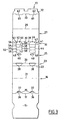
- la figure 3 est une vue schématique en plan d'un flan de carton pour former le fourreau extérieur de l'emballage de la figure 1,
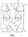
- la figure 4 est une vue analogue illustrant un flan de carton pour former l'intercalaire de l'emballage de la figure 1, et
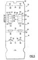
- la figure 5 est une vue analogue à la figure 3 illustrant un flan de carton pour la formation d'un emballage selon un autre mode de réalisation de l'invention.
- FIG. 1 is a schematic perspective view of an assembly comprising a group of containers packaged in a package according to the invention,
- FIG. 2 is a diagrammatic, enlarged, partial and perspective view illustrating the interlayer of the package of FIG. 1 and its cooperation with two containers,
- FIG. 3 is a diagrammatic plan view of a carton blank for forming the outer sleeve of the package of FIG. 1,
- FIG. 4 is a similar view illustrating a blank of cardboard to form the interlayer of the package of FIG. 1, and
- Figure 5 is a view similar to Figure 3 illustrating a blank of cardboard for the formation of a package according to another embodiment of the invention.
La figure 1 représente un ensemble 1 comprenant un groupe 2 de huit pots de yaourt 3 et un emballage 4.FIG. 1 represents a set 1 comprising a group 2 of eight jars of yogurt 3 and a package 4.
Les pots 3 sont identiques, disposés verticalement et ont par exemple une forme générale tronconique convergeant vers le bas. Comme illustré par exemple par la figure 2, les pots 3 présentent chacun à leur extrémité ouverte supérieure un rebord annulaire 6 et un opercule circulaire 7 fermant cette extrémité ouverte.The pots 3 are identical, arranged vertically and have for example a generally frustoconical shape converging downwards. As illustrated for example in Figure 2, the pots 3 each have at their upper open end an annular rim 6 and a circular seal 7 closing this open end.
Les pots 3 ont été représentés en traits mixtes sur les figures 1 et 2 et certains pots 3 n'ont pas été représentés pour plus de visibilité.The pots 3 have been shown in phantom in Figures 1 and 2 and some pots 3 have not been shown for more visibility.
Les pots 3 sont disposés en deux niveaux superposés, à savoir un niveau inférieur de quatre pots 3, et un niveau supérieur de quatre pots 3.The pots 3 are arranged in two superimposed levels, namely a lower level of four pots 3, and a top level of four pots 3.
Les pots 3 du niveau supérieur surmontent chacun un pot 3 du niveau inférieur.The pots 3 of the upper level each surmount a pot 3 of the lower level.
Pour chaque niveau, les quatre pots 3 sont régulièrement disposés en deux rangées 10 s'étendant selon une direction longitudinale L de l'emballage 4.For each level, the four pots 3 are regularly arranged in two
L'emballage 4 comprend un fourreau extérieur 11 qui enveloppe extérieurement le groupe 2, et un intercalaire 12 disposé entre le niveau inférieur et le niveau supérieur de pots 3.The package 4 comprises an
Les structures du fourreau 11 puis de l'intercalaire 12 vont maintenant être décrites à partir des figures 1 à 4. Dans cette description, les termes « longitudinal », « transversal », « vertical », « horizontal », « avant », « arrière », « inférieur », « supérieur », « droite » et « gauche » s'entendront par rapport à l'emballage 4 tel que représenté sur les figures 1 et 2.The structures of the
Le fourreau 11, qui est formé à partir d'un flan de carton 13 préalablement découpé et rainé (figure 3), comprend principalement :
- une paroi supérieure 15 sensiblement rectangulaire,
- une paroi latérale droite 16 sensiblement rectangulaire reliée à la paroi supérieure 15 par une ligne de
pliage 17 longitudinale, laparoi 16 présentant en outre une ligne depliage 21 médiane et longitudinale et une ligne depliage 22 inférieure et longitudinale qui délimite une région inférieure 23, - une paroi inférieure 25, de forme générale rectangulaire et de dimensions correspondant sensiblement à celles de la paroi supérieure 15, et reliée à la paroi latérale 16 par une ligne de
pliage 26 longitudinale, - une paroi latérale gauche 27 par exemple de mêmes dimensions que la paroi latérale droite 16, reliée à la paroi inférieure 25 par une ligne de
pliage 28 longitudinale, la paroi latérale gauche 27 comprenant une ligne depliage 29 médiane et longitudinale et une ligne depliage 30 inférieure et longitudinale délimitant une région inférieure 31, et - un
rabat 32 de fixation de la paroi latérale gauche 27 à la paroi supérieure 15, cerabat 32 étant relié à la paroi latérale gauche 27 par une ligne depliage 33 longitudinale.
- a substantially rectangular
upper wall 15, - a substantially rectangular
right side wall 16 connected to theupper wall 15 by alongitudinal fold line 17, thewall 16 further having a median andlongitudinal fold line 21 and a lower andlongitudinal fold line 22 which delimits alower region 23 , - a
bottom wall 25 of generally rectangular shape and of dimensions substantially corresponding to those of theupper wall 15, and connected to theside wall 16 by alongitudinal fold line 26, - a left
lateral wall 27, for example of the same dimensions as the rightlateral wall 16, connected to thelower wall 25 by alongitudinal fold line 28, the leftlateral wall 27 comprising a median andlongitudinal fold line 29 and a fold line Lower and longitudinal delimiting alower region 31, and - a
flap 32 for fixing the left-hand side wall 27 to theupper wall 15, thisflap 32 being connected to the left-hand side wall 27 by alongitudinal fold line 33.
La ligne de pliage 17 est interrompue par deux découpes 35 ménagées dans la paroi latérale droite 16. Ces découpes 35 délimitent deux rebords 36 prolongeant la paroi supérieure 15 et deux dégagements 37 sensiblement rectangulaires.The
Deux ouvertures 38 en forme de secteur de disque sont ménagées dans la région inférieure 23 de la paroi latérale droite 16.Two disc-
Deux fentes oblongues 40 sont ménagées sensiblement au centre de la paroi inférieure 25, en regard des ouvertures 38.Two oblong
Deux découpes 41 sont ménagées dans la région inférieure 31 de la paroi latérale gauche 27 et dans la paroi inférieure 25. Ces découpes 41 comprennent chacune un tronçon 42 en arc de cercle ménagé dans la région 31. Les tronçons 42 ont par exemple une forme correspondant au contour des ouvertures 38. Les tronçons 42 sont prolongés chacun par deux tronçons courbes d'extrémité 44 qui s'étendent dans la paroi inférieure 25 vers les fentes 40.Two
Les découpes 41 délimitent deux volets 46 qui sont reliés à la paroi inférieure 25 par des lignes de pliage 48 qui s'entendent chacune entre les extrémités des deux tronçons 44 de la découpe 41 correspondante.The
Chaque volet 46 est donc découpé du côté gauche (en haut sur la figure 3) de la ligne de pliage 48 correspondante.Each
Chaque volet 46 comprend depuis la ligne de pliage 48 correspondante quatre panneaux successifs 50, 52, 54, 56 séparés par des lignes de pliage 58 longitudinales.Each
Le panneau 56 le plus éloigné de la ligne de pliage 48, dénommé par la suite panneau d'extrémité, a une forme de secteur de disque.The
La ligne de pliage 33 est interrompue par deux découpes 60 en U qui délimitent des rebords 62 prolongeant le rabat 32 de fixation.The
Dans le fourreau 11 mis en volume (figure 1), les volets 46 sont repliés depuis le côté situé à gauche des lignes de pliage 48 vers le côté situé à droite de celles-ci. Les panneaux d'extrémité 56 sont collés sur la paroi inférieure 25, à droite des lignes de pliage 48 et au-delà des fentes oblongues 40.In the
Les panneaux 50, 52, 54 et 56 sont alors pliés les uns par rapport aux autres autour des lignes de pliage 58 sensiblement à angles droits, comme illustré par la figure 1.The
Chaque volet 46 forme ainsi une poutre 64 de section sensiblement carrée. En variante, cette section peut être rectangulaire. La poutre 64 est située à droite de la ligne de pliage 48 correspondante, alors que le volet 46 a été découpé à gauche de cette ligne de pliage 48.Each
Les parois latérales 16 et 27 sont repliées vers le haut par rapport à la paroi inférieure 25.The
La formation des poutres 64 a dégagé dans la région inférieure 31 de la paroi latérale gauche 27 deux ouvertures 38 de forme correspondante à celle des ouvertures 38 ménagées dans la région inférieure 23 de la paroi latérale droite 16.The formation of the
Les extrémités inférieures des pots 3 inférieurs sont engagés dans les ouvertures 38 de la paroi latérale droite 16 et de la paroi latérale gauche 27, en assurant ainsi une retenue longitudinale des pots 3 inférieurs par rapport au fourreau 11.The lower ends of the lower pots 3 are engaged in the
Les deux poutres 64 font saillie vers le haut depuis la paroi inférieure 25 entre les rangées droite et gauche des pots 3 inférieurs.The two
Ainsi, la poutre 64 avant sur la figure 1 est disposée entre les pots 3 inférieurs avant, et la poutre arrière 64 est disposée entre les pots 3 inférieurs arrière.Thus, the
Les poutres 64 maintiennent transversalement les pots 3 inférieurs et les plaquent notamment au fond des ouvertures 38.The
Les pots 3 inférieurs droits reposent chacun sur le panneau d'extrémité 56 de la poutre 64 correspondante.The lower right pots 3 each rest on the
Le rabat supérieur 32 est plié par rapport à la paroi latérale gauche 27 et collé sous la paroi supérieure 15 qui est elle-même pliée par rapport à la paroi latérale droite 16.The
Le pliage du rabat 32 a libéré dans la paroi latérale gauche 27 des ouvertures 68 qui reçoivent les rebords supérieurs 6 des pots 3 supérieurs gauches. Ces ouvertures 68 vont assurer une retenue longitudinale des pots 3 supérieurs gauches.Folding the
De même, le pliage de la paroi supérieure 15 par rapport à la paroi latérale droite 16 a libéré dans la paroi latérale 16 des ouvertures de réception des rebords supérieurs 6 des pots 3 supérieurs droits.Similarly, the folding of the
L'intercalaire 12 (figure 2), qui est formé à partir d'un flan de carton 72 préalablement découpé et rainé (figure 4), comprend principalement :
- une paroi centrale 74 sensiblement rectangulaire,
- un rabat latéral droit 76 relié au panneau central 74 par une ligne de pliage 78 longitudinale interrompue par deux découpes 80 en forme de U délimitant deux rebords 82 prolongeant la paroi centrale 74, et
- un rabat latéral gauche 84 relié à la paroi centrale 74 par une ligne de pliage 86 longitudinale interrompue par deux découpes 88 en forme de U délimitant deux rebords 90 prolongeant la paroi centrale 74.
- a
central wall 74 substantially rectangular, - a right
lateral flap 76 connected to thecentral panel 74 by alongitudinal fold line 78 interrupted by twoU-shaped cutouts 80 delimiting twoflanges 82 extending thecentral wall 74, and - a left
lateral flap 84 connected to thecentral wall 74 by alongitudinal fold line 86 interrupted by twoU-shaped cutouts 88 delimiting twoflanges 90 extending thecentral wall 74.
Deux fentes oblongues 92 sont ménagées au centre de la paroi centrale 74 l'une derrière l'autre.Two
Une patte femelle 94 est découpée dans la paroi centrale 74 à gauche de chaque fente 92 et une patte mâle 96 est découpée dans la paroi centrale 74 à droite de chaque fente 92.A
Les pattes femelles 94 et les pattes mâles 96 ont sensiblement des formes de U inversé. Elles sont reliées au reste de la paroi centrale 74 par des lignes de pliage 98 longitudinales disposées aux extrémités des branches des pattes 94 et 96.The
Une encoche 100 en forme de secteur de disque est ménagée dans chaque patte femelle 94.A
Chaque patte mâle 96 est prolongée par une languette 102 en forme de demi-disque.Each
Dans l'ensemble 1 de la figure 1, les rabats latéraux 76 et 84 sont repliés vers le bas par rapport à la paroi centrale 74 en dégageant ainsi des ouvertures 104 (figure 2) dans les rabats latéraux 76 et 84.In the assembly 1 of Figure 1, the side flaps 76 and 84 are folded downward relative to the
L'intercalaire 12 est disposé à l'intérieur du fourreau 11 et la paroi centrale 74 recouvre les pots 3 inférieurs tandis que les pots 3 supérieurs reposent sur la paroi centrale 74.The
Les rebords supérieurs 6 des pots 3 inférieurs sont engagés chacun dans une ouverture 104 en assurant ainsi une retenue longitudinale des pots 3 inférieurs par rapport à l'intercalaire 12.The upper flanges 6 of the lower pots 3 are each engaged in an
Les pattes 94 et 96 bordant chaque fente 92 sont repliées l'une vers l'autre au-dessus de la paroi centrale 74 pour former un élément de retenue 106 en forme de tréteau. La languette 102 de la patte mâle 96 est alors engagée dans l'encoche 100 de la patte femelle 94 en assurant ainsi la tenue de l'élément de retenue 106.The
Les deux éléments de retenue 106 ainsi formés sont disposés l'un derrière l'autre au-dessus de la paroi centrale 74, l'élément 106 avant étant disposé entre les pots 3 supérieurs avant et l'élément 106 arrière entre les pots 3 supérieurs arrière.The two retaining
Le pliage des pattes 94 et 96 a libéré entre leurs branches des dégagements 108 semi-circulaires. Chaque dégagement 108 reçoit l'extrémité inférieure d'un pot 3 supérieur.The folding of the
Ainsi, les éléments de retenue 106 retiennent les pots 3 supérieurs à la fois longitudinalement et transversalement par rapport à l'intercalaire 12.Thus, the retaining
Pour former l'ensemble 1, on peut par exemple procéder comme suit.To form the assembly 1, one can for example proceed as follows.
On commence par former les poutres 64 sur la paroi inférieure 25 du fourreau 11 puis on dispose les pots 3 inférieurs sur la paroi inférieure 25.The
On dispose ensuite l'intercalaire 12 sur les pots 3 inférieurs après avoir formé les éléments de retenue 106 sur la paroi centrale 74.The
On place ensuite les pots 3 supérieurs sur l'intercalaire 12 puis on replie les parois latérales 16 et 27 du fourreau 11 pour venir envelopper le groupe 2 de pots 3.The upper pots 3 are then placed on the
Enfin, on vient fixer la paroi supérieure 15 sur le rabat de fixation 32 par collage.Finally, the
On notera que les fentes 40 et 92 prévues dans les flans 13 et 72 permettent de les manipuler facilement grâce à des ventouses et donc d'automatiser la réalisation de l'ensemble 1.It will be noted that the
Les volets 46 étant découpés chacun d'un même côté d'une ligne de pliage 48 et repliés au-dessus de la paroi inférieure 25 de l'autre côté de cette ligne de pliage 48, la paroi inférieure 25 peut être de dimensions réduites. Le coût du flan 13 et de l'emballage 4 est donc particulièrement réduit.The
En outre, on observera que la structure des poutres 64 formées par les volets 46, et en particulier leur section, leur confère une rigidité importante de sorte que la taille des ouvertures 38 peut être réduite. Ainsi, les risques de déchirement du fourreau 11 sont réduits et un carton de faible grammage ou un carton recyclé peut être utilisé pour former le fourreau 11, ce qui permet encore d'en réduire le coût.In addition, it will be observed that the structure of the
De plus, les panneaux 56, sur lesquels les pots 3 inférieurs droits s'appuient, contribuent également à la solidité des poutres 64.In addition, the
L'intercalaire 12 interposé entre les pots 3 inférieurs et les pots 3 supérieurs permet de protéger les opercules des pots 3 inférieurs.The
En outre, les ouvertures 104 forment des moyens de retenue des pots 3 inférieurs qui, en combinaison avec les éléments de retenue 106 des pots 3 supérieurs, permettent un maintien satisfaisant des pots 3 dans le fourreau 11.In addition, the
On notera que ces moyens 104 et 106 de retenue n'entraînent pas une surconsommation de carton.It will be noted that these retention means 104 and 106 do not cause overconsumption of cardboard.
On remarquera que la structure auto-portante des éléments de retenue 106 permet également de réduire le grammage du carton utilisé pour former l'intercalaire 12 de sorte que le coût global de l'emballage 4 peut être réduit.It will be appreciated that the self-supporting structure of the
De plus, les deux parois latérales 16 et 27 ne sont pas découpées ou détériorées pour assurer la retenue des pots 3 inférieurs par rapport aux pots 3 supérieurs.In addition, the two
De manière plus générale, les poutres de maintien 64 et les moyens de retenue 104 et 106 peuvent avoir des formes différentes de celles décrites précédemment.More generally, the holding
On notera en outre que ces deux aspects peuvent être utilisés indépendamment l'un de l'autre.It should be noted further that these two aspects can be used independently of one another.
Ainsi, on peut utiliser un intercalaire 12 à moyens 104 et 106 de retenue sans utiliser la structure d'éléments de maintien 64 dans la paroi inférieure 25 du fourreau 11.Thus, it is possible to use a
L'inverse est également vrai et illustré par la figure 5 qui représente un flan 13 pour former un fourreau 11 selon un second mode de réalisation.The opposite is also true and illustrated in Figure 5 which shows a blank 13 to form a
Ce flan 13 se distingue de celui de la figure 3 par le fait que les parois latérales 16 et 27 sont de hauteur plus réduite et ne comportent pas de ligne de pliage médiane. Ainsi, ce flan 13 est destiné à former un emballage 4 de conditionnement d'un groupe de pots 3 disposés en un seul niveau. L'emballage 4 ne comprend donc pas d'intercalaire 12.This blank 13 differs from that of Figure 3 in that the
Les principes décrits ci-dessus peuvent également s'appliquer au conditionnement de pots 3 dont les extrémités supérieures sont reliées entre elles, par exemple des pots de yaourt réalisés par thermoformage d'une plaque en matière plastique.The principles described above can also be applied to the packaging pots 3 whose upper ends are interconnected, for example yogurt pots made by thermoforming a plastic plate.
De manière plus générale, ces principes peuvent être utilisés pour conditionner d'autres types de récipients que des pots de yaourt.More generally, these principles can be used to package other types of containers than yoghurt pots.
Claims (12)
- Packaging (4) for packaging a group (2) of at least two containers (3), the packaging being of the type comprising at least one sleeve (11) extending longitudinally and comprising an upper wall (15), a lower wall (25), two lateral walls (16, 27) connecting the lower and upper walls, and at least one element (64) for retaining the containers (3), the retaining element (64) projecting from the lower wall (25) so that it lies between the containers (3), the retaining element (64) comprising a flap (46) cut into the lower wall (25) and folded around a folding line (48), and the flap being cut out from the lower wall (25) on a first side of a folding line (48), characterised in that the flap (46) is folded and fixed relative to the lower wall (25) on the side of the folding line (48) opposite the first side.
- Packaging according to claim 1, characterised in that the folding line (48) extends substantially longitudinally and in that the retaining element (64) is adapted to retain the containers (3) transversely.
- Packaging according to claim 1 or claim 2, characterised in that the flap (46) comprises an end region (56) by means of which it is fixed to the lower wall (25).
- Packaging according to claim 3, characterised in that the end region (56) of the flap (46) is glued to the lower wall (25).
- Packaging according to claim 3 or claim 4, characterised in that the flap (46) comprises a plurality of successive regions (50, 52, 54, 56) connected to each other by folding lines (58), the retaining element (64) having a quadrilateral section.
- Packaging according to any one of the preceding claims, characterised in that, the group (2) comprising at least a bottom layer of containers (3) and a top layer of containers (3), the packaging further comprises an insert (12) adapted to be placed between the bottom layer and the top layer of containers (3).
- Packaging according to claim 6, characterised in that the insert (12) comprises first retaining means (104) for retaining the containers (3) of the bottom layer and second retaining means (106) for retaining the containers (3) of the top layer relative to the insert (12).
- Packaging according to claim 7, characterised in that the first retaining means comprise apertures (104) adapted to receive upper regions of containers (3) of the bottom layer.
- Packaging according to claim 7 or claim 8, characterised in that the second retaining means (106) project upward from the insert (12) so as to be disposed between the containers (3) of the top layer.
- Packaging according to claim 9, characterised in that the second retaining means comprise at least two tabs (94, 96) cut out from the insert (12), folded and engaged one within the other.
- A combination comprising a group (2) of at least two containers (3) and packaging (4) in which the group is packaged, characterised in that the packaging is packaging according to any one of the preceding claims.
- A pre-cut cardboard blank with scored lines adapted to form the sleeve (11) of packaging according to any one of claims 1 to 10, the blank comprising an upper wall (15), a lower wall (25), two lateral walls (16, 27) adapted to connect the lower and upper walls, and a flap (46) cut out from the lower wall (25) on a first side of a folding line (48), the flap (46) being adapted to be folded abour the folding line (48) and fixed to the lower wall (25) on the opposite side of the folding line (48) to the first side and thus to form a container-retaining element (64) projecting from the lower wall (25) so as to lie between containers (3).
Applications Claiming Priority (2)
| Application Number | Priority Date | Filing Date | Title |
|---|---|---|---|
| FR0216563 | 2002-12-23 | ||
| FR0216563A FR2848993B1 (en) | 2002-12-23 | 2002-12-23 | PACKAGING COMPRISING AN OVEN WITH AT LEAST ONE CONTAINER HOLDING ELEMENT, TOGETHER COMPRISING SUCH PACKAGING AND CORRESPONDING CONTAINERS AND FLANKS. |
Publications (2)
| Publication Number | Publication Date |
|---|---|
| EP1433713A1 EP1433713A1 (en) | 2004-06-30 |
| EP1433713B1 true EP1433713B1 (en) | 2006-03-15 |
Family
ID=32406437
Family Applications (1)
| Application Number | Title | Priority Date | Filing Date |
|---|---|---|---|
| EP03292877A Expired - Lifetime EP1433713B1 (en) | 2002-12-23 | 2003-11-18 | Package comprising a sleeve with at least a container retaining element |
Country Status (6)
| Country | Link |
|---|---|
| EP (1) | EP1433713B1 (en) |
| AT (1) | ATE320389T1 (en) |
| DE (1) | DE60304020T2 (en) |
| ES (1) | ES2260591T3 (en) |
| FR (1) | FR2848993B1 (en) |
| PT (1) | PT1433713E (en) |
Family Cites Families (6)
| Publication number | Priority date | Publication date | Assignee | Title |
|---|---|---|---|---|
| US4703847A (en) * | 1987-01-30 | 1987-11-03 | The Mead Corporation | Multipack for flanged primary containers |
| GB2207904B (en) * | 1987-08-13 | 1991-01-30 | Bonar Cooke Cartons Ltd | Carton |
| DE3928076A1 (en) * | 1989-08-25 | 1991-02-28 | Unilever Nv | Multiple container packing carrier - has central web which has several punched-out tab |
| FR2723353B1 (en) * | 1994-08-02 | 1996-10-31 | 4 P Emballages France | OVERPACKING FOR A SET OF OBJECTS SUCH AS INDIVIDUAL COLLAR POTS, PROVIDED WITH IMPROVED SETTING MEANS |
| US5638956A (en) * | 1995-12-11 | 1997-06-17 | Riverwood International Corporation | Wrap-around carrier with lock-box keel |
| GB0010734D0 (en) * | 2000-05-04 | 2000-06-28 | Mead Corp | Carton and carton blank |
-
2002
- 2002-12-23 FR FR0216563A patent/FR2848993B1/en not_active Expired - Fee Related
-
2003
- 2003-11-18 AT AT03292877T patent/ATE320389T1/en not_active IP Right Cessation
- 2003-11-18 DE DE60304020T patent/DE60304020T2/en not_active Expired - Fee Related
- 2003-11-18 EP EP03292877A patent/EP1433713B1/en not_active Expired - Lifetime
- 2003-11-18 ES ES03292877T patent/ES2260591T3/en not_active Expired - Lifetime
- 2003-11-18 PT PT03292877T patent/PT1433713E/en unknown
Also Published As
| Publication number | Publication date |
|---|---|
| PT1433713E (en) | 2006-06-30 |
| DE60304020T2 (en) | 2006-11-02 |
| FR2848993B1 (en) | 2005-07-08 |
| FR2848993A1 (en) | 2004-06-25 |
| ES2260591T3 (en) | 2006-11-01 |
| EP1433713A1 (en) | 2004-06-30 |
| ATE320389T1 (en) | 2006-04-15 |
| DE60304020D1 (en) | 2006-05-11 |
Similar Documents
| Publication | Publication Date | Title |
|---|---|---|
| EP2225162B1 (en) | Packing case with centring tab, set of cutouts and method for creating such a case | |
| EP0615920B1 (en) | Cardboard blank for forming a tubular envelope to hold a group of containers and package thus obtained | |
| EP0461947B1 (en) | Packaging device for group of articles | |
| WO2012059655A1 (en) | Tray having raised edges and rounded centering devices, and blank for producing such a tray | |
| EP1433713B1 (en) | Package comprising a sleeve with at least a container retaining element | |
| EP0738664B1 (en) | Selfsupporting paperboard sales package,in particular for thermoformed pots | |
| EP0972718B1 (en) | Wrap-aroud package, blank and assembly comprising the package wraped around objects | |
| FR2853886A1 (en) | Parallelepiped case for packing and transporting object, has base with central panel including flaps that are fixed on external peripheral part of front shutter which defines central recess with top to capture object | |
| FR2631314A1 (en) | Improved stackable container for storage and transport | |
| FR2780703A1 (en) | Package made from semi rigid material for diverse items | |
| EP1279618B1 (en) | Closed packaging case and lid made of different materials | |
| EP0223623A1 (en) | Cross-section for forming compartments in a goods container | |
| FR2733740A1 (en) | Package for grouped objects, e.g. containers of drink, made from two or more cardboard panels and interlocking elements | |
| EP0885150A1 (en) | Grouping element for assembling packages containing pots arranged in layers | |
| FR2813588A1 (en) | Packaging for group of containers comprises side walls and lower and upper end walls with transverse retaining band for holding containers | |
| FR3052444B1 (en) | PACKAGING TYPE CAISSE AMERICAN AUTOMATIC BACKGROUND OR SEMI-AUTOMATIC SECURE. | |
| EP0614821A1 (en) | Blank and device for holding and gripping layers of containers | |
| FR2832389A1 (en) | Packaging for yogurt pots connected by upper ends comprises upper, front, lower and rear walls. Latter comprising lower band passing between two successive pots | |
| FR2600307A1 (en) | Package for bottles laid head-to-tail | |
| FR2813589A1 (en) | Packaging for group of containers comprises side walls and lower and upper end walls with transverse retaining strap for containers located near lower end wall | |
| EP1279617B1 (en) | Closed package as rigid crate and corresponding assembly of two blanks | |
| EP2383191B1 (en) | Stapelfähige Faltschale aus Karton, und Zuschnitt zur Herstellung einer solchen Platte | |
| FR2719561A1 (en) | Corrugated cardboard package for bottles | |
| FR2813587A1 (en) | Packaging for group of containers located in two levels comprises side walls lower and upper end walls and tongue separating containers in two levels | |
| FR2795049A1 (en) | Set of blanks for construction of folding crate form tray and lid and crate has transverse side wall which may be manually torn from remainder of crate |
Legal Events
| Date | Code | Title | Description |
|---|---|---|---|
| PUAI | Public reference made under article 153(3) epc to a published international application that has entered the european phase |
Free format text: ORIGINAL CODE: 0009012 |
|
| AK | Designated contracting states |
Kind code of ref document: A1 Designated state(s): AT BE BG CH CY CZ DE DK EE ES FI FR GB GR HU IE IT LI LU MC NL PT RO SE SI SK TR |
|
| AX | Request for extension of the european patent |
Extension state: AL LT LV MK |
|
| 17P | Request for examination filed |
Effective date: 20041210 |
|
| 17Q | First examination report despatched |
Effective date: 20050208 |
|
| AKX | Designation fees paid |
Designated state(s): AT BE BG CH CY CZ DE DK EE ES FI FR GB GR HU IE IT LI LU MC NL PT RO SE SI SK TR |
|
| GRAP | Despatch of communication of intention to grant a patent |
Free format text: ORIGINAL CODE: EPIDOSNIGR1 |
|
| GRAS | Grant fee paid |
Free format text: ORIGINAL CODE: EPIDOSNIGR3 |
|
| GRAA | (expected) grant |
Free format text: ORIGINAL CODE: 0009210 |
|
| AK | Designated contracting states |
Kind code of ref document: B1 Designated state(s): AT BE BG CH CY CZ DE DK EE ES FI FR GB GR HU IE IT LI LU MC NL PT RO SE SI SK TR |
|
| PG25 | Lapsed in a contracting state [announced via postgrant information from national office to epo] |
Ref country code: IT Free format text: LAPSE BECAUSE OF FAILURE TO SUBMIT A TRANSLATION OF THE DESCRIPTION OR TO PAY THE FEE WITHIN THE PRESCRIBED TIME-LIMIT;WARNING: LAPSES OF ITALIAN PATENTS WITH EFFECTIVE DATE BEFORE 2007 MAY HAVE OCCURRED AT ANY TIME BEFORE 2007. THE CORRECT EFFECTIVE DATE MAY BE DIFFERENT FROM THE ONE RECORDED. Effective date: 20060315 Ref country code: SK Free format text: LAPSE BECAUSE OF FAILURE TO SUBMIT A TRANSLATION OF THE DESCRIPTION OR TO PAY THE FEE WITHIN THE PRESCRIBED TIME-LIMIT Effective date: 20060315 Ref country code: SI Free format text: LAPSE BECAUSE OF FAILURE TO SUBMIT A TRANSLATION OF THE DESCRIPTION OR TO PAY THE FEE WITHIN THE PRESCRIBED TIME-LIMIT Effective date: 20060315 Ref country code: IE Free format text: LAPSE BECAUSE OF FAILURE TO SUBMIT A TRANSLATION OF THE DESCRIPTION OR TO PAY THE FEE WITHIN THE PRESCRIBED TIME-LIMIT Effective date: 20060315 Ref country code: FI Free format text: LAPSE BECAUSE OF FAILURE TO SUBMIT A TRANSLATION OF THE DESCRIPTION OR TO PAY THE FEE WITHIN THE PRESCRIBED TIME-LIMIT Effective date: 20060315 Ref country code: AT Free format text: LAPSE BECAUSE OF FAILURE TO SUBMIT A TRANSLATION OF THE DESCRIPTION OR TO PAY THE FEE WITHIN THE PRESCRIBED TIME-LIMIT Effective date: 20060315 Ref country code: RO Free format text: LAPSE BECAUSE OF FAILURE TO SUBMIT A TRANSLATION OF THE DESCRIPTION OR TO PAY THE FEE WITHIN THE PRESCRIBED TIME-LIMIT Effective date: 20060315 |
|
| REG | Reference to a national code |
Ref country code: GB Ref legal event code: FG4D Free format text: NOT ENGLISH Ref country code: CH Ref legal event code: EP |
|
| GBT | Gb: translation of ep patent filed (gb section 77(6)(a)/1977) |
Effective date: 20060315 |
|
| REG | Reference to a national code |
Ref country code: IE Ref legal event code: FG4D Free format text: LANGUAGE OF EP DOCUMENT: FRENCH |
|
| REF | Corresponds to: |
Ref document number: 60304020 Country of ref document: DE Date of ref document: 20060511 Kind code of ref document: P |
|
| PG25 | Lapsed in a contracting state [announced via postgrant information from national office to epo] |
Ref country code: SE Free format text: LAPSE BECAUSE OF FAILURE TO SUBMIT A TRANSLATION OF THE DESCRIPTION OR TO PAY THE FEE WITHIN THE PRESCRIBED TIME-LIMIT Effective date: 20060615 Ref country code: DK Free format text: LAPSE BECAUSE OF FAILURE TO SUBMIT A TRANSLATION OF THE DESCRIPTION OR TO PAY THE FEE WITHIN THE PRESCRIBED TIME-LIMIT Effective date: 20060615 Ref country code: BG Free format text: LAPSE BECAUSE OF FAILURE TO SUBMIT A TRANSLATION OF THE DESCRIPTION OR TO PAY THE FEE WITHIN THE PRESCRIBED TIME-LIMIT Effective date: 20060615 |
|
| REG | Reference to a national code |
Ref country code: PT Ref legal event code: SC4A Effective date: 20060421 |
|
| REG | Reference to a national code |
Ref country code: IE Ref legal event code: FD4D |
|
| REG | Reference to a national code |
Ref country code: ES Ref legal event code: FG2A Ref document number: 2260591 Country of ref document: ES Kind code of ref document: T3 |
|
| PG25 | Lapsed in a contracting state [announced via postgrant information from national office to epo] |
Ref country code: MC Free format text: LAPSE BECAUSE OF NON-PAYMENT OF DUE FEES Effective date: 20061130 |
|
| PLBE | No opposition filed within time limit |
Free format text: ORIGINAL CODE: 0009261 |
|
| STAA | Information on the status of an ep patent application or granted ep patent |
Free format text: STATUS: NO OPPOSITION FILED WITHIN TIME LIMIT |
|
| 26N | No opposition filed |
Effective date: 20061218 |
|
| REG | Reference to a national code |
Ref country code: FR Ref legal event code: TP |
|
| PGFP | Annual fee paid to national office [announced via postgrant information from national office to epo] |
Ref country code: DE Payment date: 20071108 Year of fee payment: 5 Ref country code: ES Payment date: 20071119 Year of fee payment: 5 Ref country code: NL Payment date: 20071017 Year of fee payment: 5 |
|
| PGFP | Annual fee paid to national office [announced via postgrant information from national office to epo] |
Ref country code: IT Payment date: 20071115 Year of fee payment: 5 |
|
| PGFP | Annual fee paid to national office [announced via postgrant information from national office to epo] |
Ref country code: BE Payment date: 20071203 Year of fee payment: 5 |
|
| PG25 | Lapsed in a contracting state [announced via postgrant information from national office to epo] |
Ref country code: GR Free format text: LAPSE BECAUSE OF FAILURE TO SUBMIT A TRANSLATION OF THE DESCRIPTION OR TO PAY THE FEE WITHIN THE PRESCRIBED TIME-LIMIT Effective date: 20060616 Ref country code: CZ Free format text: LAPSE BECAUSE OF FAILURE TO SUBMIT A TRANSLATION OF THE DESCRIPTION OR TO PAY THE FEE WITHIN THE PRESCRIBED TIME-LIMIT Effective date: 20060315 |
|
| PGFP | Annual fee paid to national office [announced via postgrant information from national office to epo] |
Ref country code: GB Payment date: 20071114 Year of fee payment: 5 |
|
| PGFP | Annual fee paid to national office [announced via postgrant information from national office to epo] |
Ref country code: PT Payment date: 20071017 Year of fee payment: 5 |
|
| PG25 | Lapsed in a contracting state [announced via postgrant information from national office to epo] |
Ref country code: EE Free format text: LAPSE BECAUSE OF FAILURE TO SUBMIT A TRANSLATION OF THE DESCRIPTION OR TO PAY THE FEE WITHIN THE PRESCRIBED TIME-LIMIT Effective date: 20060315 |
|
| PG25 | Lapsed in a contracting state [announced via postgrant information from national office to epo] |
Ref country code: HU Free format text: LAPSE BECAUSE OF FAILURE TO SUBMIT A TRANSLATION OF THE DESCRIPTION OR TO PAY THE FEE WITHIN THE PRESCRIBED TIME-LIMIT Effective date: 20060916 Ref country code: LI Free format text: LAPSE BECAUSE OF NON-PAYMENT OF DUE FEES Effective date: 20071130 Ref country code: TR Free format text: LAPSE BECAUSE OF FAILURE TO SUBMIT A TRANSLATION OF THE DESCRIPTION OR TO PAY THE FEE WITHIN THE PRESCRIBED TIME-LIMIT Effective date: 20060315 Ref country code: CH Free format text: LAPSE BECAUSE OF NON-PAYMENT OF DUE FEES Effective date: 20071130 Ref country code: LU Free format text: LAPSE BECAUSE OF NON-PAYMENT OF DUE FEES Effective date: 20061118 |
|
| REG | Reference to a national code |
Ref country code: CH Ref legal event code: PL |
|
| PG25 | Lapsed in a contracting state [announced via postgrant information from national office to epo] |
Ref country code: CY Free format text: LAPSE BECAUSE OF FAILURE TO SUBMIT A TRANSLATION OF THE DESCRIPTION OR TO PAY THE FEE WITHIN THE PRESCRIBED TIME-LIMIT Effective date: 20060315 |
|
| REG | Reference to a national code |
Ref country code: PT Ref legal event code: MM4A Free format text: LAPSE DUE TO NON-PAYMENT OF FEES Effective date: 20090518 |
|
| BERE | Be: lapsed |
Owner name: GOOSSENS BEAUVAIS Effective date: 20081130 |
|
| GBPC | Gb: european patent ceased through non-payment of renewal fee |
Effective date: 20081118 |
|
| PG25 | Lapsed in a contracting state [announced via postgrant information from national office to epo] |
Ref country code: NL Free format text: LAPSE BECAUSE OF NON-PAYMENT OF DUE FEES Effective date: 20090601 |
|
| NLV4 | Nl: lapsed or anulled due to non-payment of the annual fee |
Effective date: 20090601 |
|
| PG25 | Lapsed in a contracting state [announced via postgrant information from national office to epo] |
Ref country code: PT Free format text: LAPSE BECAUSE OF NON-PAYMENT OF DUE FEES Effective date: 20090518 Ref country code: IT Free format text: LAPSE BECAUSE OF NON-PAYMENT OF DUE FEES Effective date: 20081118 |
|
| PG25 | Lapsed in a contracting state [announced via postgrant information from national office to epo] |
Ref country code: BE Free format text: LAPSE BECAUSE OF NON-PAYMENT OF DUE FEES Effective date: 20081130 |
|
| PG25 | Lapsed in a contracting state [announced via postgrant information from national office to epo] |
Ref country code: DE Free format text: LAPSE BECAUSE OF NON-PAYMENT OF DUE FEES Effective date: 20090603 |
|
| PG25 | Lapsed in a contracting state [announced via postgrant information from national office to epo] |
Ref country code: GB Free format text: LAPSE BECAUSE OF NON-PAYMENT OF DUE FEES Effective date: 20081118 |
|
| REG | Reference to a national code |
Ref country code: ES Ref legal event code: FD2A Effective date: 20081119 |
|
| PG25 | Lapsed in a contracting state [announced via postgrant information from national office to epo] |
Ref country code: ES Free format text: LAPSE BECAUSE OF NON-PAYMENT OF DUE FEES Effective date: 20081119 |
|
| PGFP | Annual fee paid to national office [announced via postgrant information from national office to epo] |
Ref country code: FR Payment date: 20130419 Year of fee payment: 10 |
|
| REG | Reference to a national code |
Ref country code: FR Ref legal event code: ST Effective date: 20140731 |
|
| PG25 | Lapsed in a contracting state [announced via postgrant information from national office to epo] |
Ref country code: FR Free format text: LAPSE BECAUSE OF NON-PAYMENT OF DUE FEES Effective date: 20131202 |