EP1279618B1 - Closed packaging case and lid made of different materials - Google Patents
Closed packaging case and lid made of different materials Download PDFInfo
- Publication number
- EP1279618B1 EP1279618B1 EP02291655A EP02291655A EP1279618B1 EP 1279618 B1 EP1279618 B1 EP 1279618B1 EP 02291655 A EP02291655 A EP 02291655A EP 02291655 A EP02291655 A EP 02291655A EP 1279618 B1 EP1279618 B1 EP 1279618B1
- Authority
- EP
- European Patent Office
- Prior art keywords
- packaging case
- side wall
- case according
- containers
- side walls
- Prior art date
- Legal status (The legal status is an assumption and is not a legal conclusion. Google has not performed a legal analysis and makes no representation as to the accuracy of the status listed.)
- Expired - Lifetime
Links
Images


Classifications
-
- B—PERFORMING OPERATIONS; TRANSPORTING
- B65—CONVEYING; PACKING; STORING; HANDLING THIN OR FILAMENTARY MATERIAL
- B65D—CONTAINERS FOR STORAGE OR TRANSPORT OF ARTICLES OR MATERIALS, e.g. BAGS, BARRELS, BOTTLES, BOXES, CANS, CARTONS, CRATES, DRUMS, JARS, TANKS, HOPPERS, FORWARDING CONTAINERS; ACCESSORIES, CLOSURES, OR FITTINGS THEREFOR; PACKAGING ELEMENTS; PACKAGES
- B65D71/00—Bundles of articles held together by packaging elements for convenience of storage or transport, e.g. portable segregating carrier for plural receptacles such as beer cans or pop bottles; Bales of material
- B65D71/06—Packaging elements holding or encircling completely or almost completely the bundle of articles, e.g. wrappers
- B65D71/38—Packaging elements holding or encircling completely or almost completely the bundle of articles, e.g. wrappers the packaging elements, e.g. wrappers being formed by folding and interconnecting two or more blanks
-
- B—PERFORMING OPERATIONS; TRANSPORTING
- B65—CONVEYING; PACKING; STORING; HANDLING THIN OR FILAMENTARY MATERIAL
- B65D—CONTAINERS FOR STORAGE OR TRANSPORT OF ARTICLES OR MATERIALS, e.g. BAGS, BARRELS, BOTTLES, BOXES, CANS, CARTONS, CRATES, DRUMS, JARS, TANKS, HOPPERS, FORWARDING CONTAINERS; ACCESSORIES, CLOSURES, OR FITTINGS THEREFOR; PACKAGING ELEMENTS; PACKAGES
- B65D2571/00—Bundles of articles held together by packaging elements for convenience of storage or transport, e.g. portable segregating carrier for plural receptacles such as beer cans, pop bottles; Bales of material
- B65D2571/00123—Bundling wrappers or trays
- B65D2571/00129—Wrapper locking means
- B65D2571/00135—Wrapper locking means integral with the wrapper
- B65D2571/00141—Wrapper locking means integral with the wrapper glued
-
- B—PERFORMING OPERATIONS; TRANSPORTING
- B65—CONVEYING; PACKING; STORING; HANDLING THIN OR FILAMENTARY MATERIAL
- B65D—CONTAINERS FOR STORAGE OR TRANSPORT OF ARTICLES OR MATERIALS, e.g. BAGS, BARRELS, BOTTLES, BOXES, CANS, CARTONS, CRATES, DRUMS, JARS, TANKS, HOPPERS, FORWARDING CONTAINERS; ACCESSORIES, CLOSURES, OR FITTINGS THEREFOR; PACKAGING ELEMENTS; PACKAGES
- B65D2571/00—Bundles of articles held together by packaging elements for convenience of storage or transport, e.g. portable segregating carrier for plural receptacles such as beer cans, pop bottles; Bales of material
- B65D2571/00123—Bundling wrappers or trays
- B65D2571/00432—Handles or suspending means
- B65D2571/00456—Handles or suspending means integral with the wrapper
- B65D2571/00462—Straps made by two slits in a wall
-
- B—PERFORMING OPERATIONS; TRANSPORTING
- B65—CONVEYING; PACKING; STORING; HANDLING THIN OR FILAMENTARY MATERIAL
- B65D—CONTAINERS FOR STORAGE OR TRANSPORT OF ARTICLES OR MATERIALS, e.g. BAGS, BARRELS, BOTTLES, BOXES, CANS, CARTONS, CRATES, DRUMS, JARS, TANKS, HOPPERS, FORWARDING CONTAINERS; ACCESSORIES, CLOSURES, OR FITTINGS THEREFOR; PACKAGING ELEMENTS; PACKAGES
- B65D2571/00—Bundles of articles held together by packaging elements for convenience of storage or transport, e.g. portable segregating carrier for plural receptacles such as beer cans, pop bottles; Bales of material
- B65D2571/00123—Bundling wrappers or trays
- B65D2571/00432—Handles or suspending means
- B65D2571/00518—Handles or suspending means with reinforcements
- B65D2571/0053—Handles or suspending means with reinforcements attached
-
- B—PERFORMING OPERATIONS; TRANSPORTING
- B65—CONVEYING; PACKING; STORING; HANDLING THIN OR FILAMENTARY MATERIAL
- B65D—CONTAINERS FOR STORAGE OR TRANSPORT OF ARTICLES OR MATERIALS, e.g. BAGS, BARRELS, BOTTLES, BOXES, CANS, CARTONS, CRATES, DRUMS, JARS, TANKS, HOPPERS, FORWARDING CONTAINERS; ACCESSORIES, CLOSURES, OR FITTINGS THEREFOR; PACKAGING ELEMENTS; PACKAGES
- B65D2571/00—Bundles of articles held together by packaging elements for convenience of storage or transport, e.g. portable segregating carrier for plural receptacles such as beer cans, pop bottles; Bales of material
- B65D2571/00123—Bundling wrappers or trays
- B65D2571/00432—Handles or suspending means
- B65D2571/00537—Handles or suspending means with stress relieving means
- B65D2571/00543—Handles or suspending means with stress relieving means consisting of cut-outs, slits, or the like
-
- B—PERFORMING OPERATIONS; TRANSPORTING
- B65—CONVEYING; PACKING; STORING; HANDLING THIN OR FILAMENTARY MATERIAL
- B65D—CONTAINERS FOR STORAGE OR TRANSPORT OF ARTICLES OR MATERIALS, e.g. BAGS, BARRELS, BOTTLES, BOXES, CANS, CARTONS, CRATES, DRUMS, JARS, TANKS, HOPPERS, FORWARDING CONTAINERS; ACCESSORIES, CLOSURES, OR FITTINGS THEREFOR; PACKAGING ELEMENTS; PACKAGES
- B65D2571/00—Bundles of articles held together by packaging elements for convenience of storage or transport, e.g. portable segregating carrier for plural receptacles such as beer cans, pop bottles; Bales of material
- B65D2571/00123—Bundling wrappers or trays
- B65D2571/00555—Wrapper opening devices
- B65D2571/00561—Lines of weakness
- B65D2571/00574—Lines of weakness whereby contents can still be carried after the line has been torn
-
- B—PERFORMING OPERATIONS; TRANSPORTING
- B65—CONVEYING; PACKING; STORING; HANDLING THIN OR FILAMENTARY MATERIAL
- B65D—CONTAINERS FOR STORAGE OR TRANSPORT OF ARTICLES OR MATERIALS, e.g. BAGS, BARRELS, BOTTLES, BOXES, CANS, CARTONS, CRATES, DRUMS, JARS, TANKS, HOPPERS, FORWARDING CONTAINERS; ACCESSORIES, CLOSURES, OR FITTINGS THEREFOR; PACKAGING ELEMENTS; PACKAGES
- B65D2571/00—Bundles of articles held together by packaging elements for convenience of storage or transport, e.g. portable segregating carrier for plural receptacles such as beer cans, pop bottles; Bales of material
- B65D2571/00123—Bundling wrappers or trays
- B65D2571/00648—Elements used to form the wrapper
- B65D2571/00654—Blanks
- B65D2571/00666—Blanks formed from two or more sheets
-
- B—PERFORMING OPERATIONS; TRANSPORTING
- B65—CONVEYING; PACKING; STORING; HANDLING THIN OR FILAMENTARY MATERIAL
- B65D—CONTAINERS FOR STORAGE OR TRANSPORT OF ARTICLES OR MATERIALS, e.g. BAGS, BARRELS, BOTTLES, BOXES, CANS, CARTONS, CRATES, DRUMS, JARS, TANKS, HOPPERS, FORWARDING CONTAINERS; ACCESSORIES, CLOSURES, OR FITTINGS THEREFOR; PACKAGING ELEMENTS; PACKAGES
- B65D2571/00—Bundles of articles held together by packaging elements for convenience of storage or transport, e.g. portable segregating carrier for plural receptacles such as beer cans, pop bottles; Bales of material
- B65D2571/00123—Bundling wrappers or trays
- B65D2571/00709—Shape of the formed wrapper, i.e. shape of each formed element if the wrapper is made from more than one element
- B65D2571/00796—Shape of the formed wrapper, i.e. shape of each formed element if the wrapper is made from more than one element cross-like
Definitions
- the present invention relates to a packaging according to the preamble of claim 1.
- the invention applies in particular to the packaging of bottles, especially beer.
- bottles that contain it are packed in a completely wrapped closed.
- such closed packaging commonly known as a "suitcase”
- US-4,715,493 describes a package produced from two blanks distinct from the same material. A handle is formed by an attached strip.
- a grip handle is cut from the wall upper part of the cap part. To transport the packaging containing a consumer grabs this handle.
- An object of the invention is to solve this problem by providing a packaging according to the preamble of claim 1 which is more resistant to operations grip and transport and which generates reduced costs.
- the subject of the invention is a packaging according to claim 1.
- the invention further relates to an assembly according to claim 13.
- Figure 1 illustrates a closed package 1 containing a group of containers 2 of which only some have been shown.
- These containers 2 are for example beer bottles.
- the closed packaging 1 comprises a box 3 covered by a cap 4.
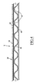
- Box 3 more particularly illustrated in Figure 2 was obtained from a blank of cardboard 6, previously cut and provided with grooves, and illustrated by figure 3.
- This blank 6 is symmetrical with respect to a transverse median axis, which is vertical in Figure 3.
- the blank 6 comprises a rectangular bottom wall panel 8 extended at its long sides by a side wall panel 10 and by a side wall panel 12, which is of reduced height than the panel 10.
- the panels 10 and 12 are connected to the bottom wall panel 8 by severely interrupted cutting lines 14 which form lines of folding. These lines 14 are horizontal (as seen in Figure 3).
- the panel 10 is extended at its short sides, that is to say to the right and to the left in FIG. 3, by flaps 16 in the form of trapezoid rectangle.
- Each flap 16 is connected to the panel 10 by a line of vertical folding 18 (as seen in Figure 3).
- the panel 12 is extended at its short sides, that is to say to the right and to the left in FIG. 3, by flaps 20 in the form of trapezoid rectangle. These shutters are each connected to the panel 12 by lines 22 vertical folding (as seen in Figure 3).
- the bottom wall panel 8 is extended at its small sides, i.e. to the right and to the left in Figure 3, by side wall panels 24. Each panel 24 is connected to panel 8 by a vertical fold line 26 (as seen in Figure 3).
- a severely interrupted central cutting line 28 is provided in each panel 24.
- This line 28 forms a fold line. She is parallel to line 26 and divides panel 24 into a first adjacent zone 30 at line 26 and which is rectangular, and in a second area 32 of shape converging towards the outside of the blank 6.
- Two interrupted cutting lines 34 extend longitudinally in the side wall panel 10 and in the adjacent flaps 16.
- the lines 34 have cusps 35 at their longitudinal ends.
- the lines 34 delimit between them a first region 36 under form of a strip and whose longitudinal ends 38 located in the flaps 16 are slightly divergent.
- the ends 38 of the first region 36 each extend over substantially half the length of the corresponding flap 16.
- the cusps 35 are oriented towards the transverse median axis of the blank 6 and towards the outside of the first region 36.
- a tab 40 is also cut from the side wall panel 10 to be adjacent to the first region 36. This tab 40 is delimited by one of the cutting lines 34 and by another curved cutting line 42.
- the blank 6 is made of corrugated cardboard comprising a flat sheet 44, which will form an inner face in the box 3, a fluted sheet 46 and a flat sheet 48, which will form an outer face in the box 3.
- the fluted sheet 46 is located between the two flat sheets 44 and 48.
- the grammage of the cardboard of the blank 6 is between about 350g / m 2 and about 500g / m 2, e.g., about 425g / m 2.
- the blank 6 comprises a straight reinforcing strip 50 which extends over the entire length of the side wall panel 10 and adjacent flaps 16. This strip 50 extends in the region 36 and therefore over its entire length.
- the strip 50 is arranged between the flat sheet 44 and the fluted sheet 46 of the blank 6.
- This strip 50 is for example made of polypropylene fibers coated with glue. It was inserted between the flat sheet 44 and the fluted sheet 46 during the blank cardboard manufacturing process 6.
- This strip 50 is orthogonal to the direction in which the grooves 52 of the grooved sheet 46 extend.
- the panels 10 and 12 are folded relative to the lower wall panel 8 thanks to lines 14 until they are orthogonal to panel 8. We fold then the flaps 16 and the flaps 20 towards the inside of the lower wall panel.
- the side wall panels 24 are then pivoted to that they are orthogonal to the lower wall panel 8. We then glue the flaps 16 and 20 by their outer faces on the inner faces of the first zones 30 of the side wall panels 24.
- the body 3 thus obtained comprises a bottom wall or bottom 8, two large opposite side walls 10 and 12 and two small side walls opposite 54.
- the walls 54 are each formed by a panel 24 and the flaps 16 and 20 correspondents.
- the side walls 10, 12 and 54 form a belt 56 extending continuously around the entire periphery of the bottom 8.
- the side walls 10, 12 and 54 and the bottom 8 delimit together four trihedra each located in a corner of the bottom 8.
- the walls 8, 10 and 54 define two trihedrons T1 and T2 situated in front in FIG. 2.
- the side walls 10, 12 and 54 came integrally with the wall lower 8 along the fold lines 14 and 26.
- the side walls 54 are on the one hand with the side wall 10 along the lines of folding 18, and on the other hand with the side wall 12 along the folding lines 22.
- the side walls 10, 12 and 54 and the bottom wall 8 are rigidly connected to each other.
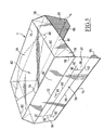
- the cap 4, illustrated more particularly by FIG. 5, is obtained from a blank of cardboard 60, previously cut and provided with grooves and illustrated by figure 6.
- the blank 60 is symmetrical with respect to a median longitudinal axis oriented vertically in Figure 6.
- the blank 60 includes a rectangular top wall panel 62 extended at its long sides, that is to say upwards and towards the bottom in FIG. 6, by panels of inclined walls 64, then by two panels side walls 66 and 67 respectively, and finally by two flaps 68.
- the inclined wall panels 64 are connected to the panel 62 by two fold lines 70 horizontal (as seen in Figure 6). These panels 64 are in the form of an isosceles trapezium diverging towards the outside of the blank 60.
- the side wall panels 66 and 67 are connected by two lines 72 horizontal folding (as seen in Figure 6) to the panels 64.
- the panels 66 and 67 are rectangular.
- the flaps 68 are connected to the side wall panels 66 and 67 by interrupted cutting lines 74 forming fold lines. These lines 74 are horizontal in Figure 6. The flaps 68 are slightly convergent to the outside of the blank 60.
- the panels 64 are extended to the right and to the left on Figure 6, that is to say at their inclined edges, by flaps 76 of substantially triangular in shape. Each flap 76 is connected to the panel 64 corresponding by an oblique fold line 78.
- the upper wall panel 62 is extended at its short sides, i.e. to the right and to the left in Figure 6, by flaps 80 in the form of an isosceles trapezoid diverging towards the outside.
- flaps 80 are connected to the upper wall panel 62 by vertical fold lines 82 (as seen in Figure 6).
- cutouts are provided in panel 62 to delimit therein.
- a diamond 84 intended to be torn, after pressing two tabs 86 cut from the flaps 80 and located in opposite corners of the rhombus 84, to allow access to the containers 2 covered by the cover 4 in packaging 1.
- the blank 60 is symmetrical with respect to a transverse median axis, oriented horizontally in Figure 6, except for what will be described later.
- Two interrupted longitudinal cutting lines 88 are provided in the side wall panel 67 (bottom in Figure 6).
- Two short interrupted 90 transverse cutting lines connect lines 88, a short distance from their ends 92.
- Lines 88 and 90 delimit between them a second region 94 in the form of a band and the ends of which are divergent.
- This second region 94 is extended at its ends by flaps 96 delimited by the ends 92 of lines 88 and by the lines 90.
- flaps 96 are articulated to the rest of the side wall panel 67 by vertical fold lines 97 (as seen in Figure 6).
- a tab 98 is cut from the panel 67 in the vicinity of the second region 94.
- This tab 96 is delimited by one of the two lines 88 and by a 99 curved cutting line.
- This tab 98 is adjacent to the second region 94.
- the cardboard used to form the blank 60 is a compact cardboard, that is to say non-corrugated.
- this carton 60 comprises for example several layers or superimposed flat sheets.
- the cardboard used for the blank 60 has a basis weight between about 250g / m 2 and about 400g / m 2 and for example about 360 g / m 2.
- the cap 4 it is rotated, thanks to the fold lines 70 and 72, the inclined wall panels 64 and the side wall panels 66 and 67 down from the top wall panel 62.
- the shutters 76 are then folded inwards towards the inside of the wall panel upper 62 thanks to the fold lines 78.
- the flaps 80 are then pivoted downwards thanks to the fold lines 82, then the flaps 76 are glued by their external faces on the internal face of the flaps 80.
- the end flaps 68 are folded towards the inside of the panel. upper walls 62 thanks to the fold lines 74.
- the flaps 68 are substantially parallel to the upper wall 62 and the side walls 66 and 67 are substantially orthogonal to the wall upper 62.
- the walls 64 and the flaps 80 are inclined at a lower angle at 90 ° to the upper wall 62.
- the containers 2 are arranged in the box 3 and are supported on its lower wall 8 by their bottoms or lower extremities.
- the containers 2 are supported on the upper wall 62 of the cap 4 by their necks or upper ends.
- the side wall 67 of the cap 4 is glued to the side wall 10 of the body 3 on the one hand under the first and second regions 36 and 94, and on the other hand above these regions 36 and 94.
- a collage is also insured between overlapping regions 36 and 94, the second region 94 having dimensions greater than those of the first region 36 as seen in Figure 1.
- the second region 94 then detaches from the rest of the panel 67 and follows the first region 36 towards the outside of the packaging 1. Regions 36 and 94 then form a grip 100 ( Figure 1) projecting from the rest of the packaging 1.
- the packaging 1 is particularly resistant to handle 100 and transport operations.
- packaging 1 being produced in two separate parts 3 and 4, blanks 6 and 60 can be supplied flat to a company having a machine for setting volume of these blanks. Due to the size reduced by these blanks, such a machine is simple and of reduced cost.
- the blanks 6 are less costly to package and deliver. as prior art sleeves which require conditioning especially at checkout.
- the blanks 6 and 60 can be stored on pallets at the output of the blank cutting and printing machines 6 and 60.
- the packaging 1 makes it possible to condition at low cost a number important beer bottles.
- the packaging 1 makes it possible to condition a group of twenty four bottles 2 divided into four rows of six bottles.
- FIG. 8 illustrates a variant of the packaging 1 of FIG. 1 in which the flaps 76 of the cover 3 are connected to the flaps 80 by lines of folding 103 obliques. Each component 76 is divided in two by a line of folding 104 oblique. The flaps 76 thus form gussets which are folded the inside of the cap 3 and which is glued to the flaps 80 to reach the structure Figures 1 and 5.
- the upper wall 62 of the cap 3 comprises a network of openings for passage of the upper ends containers 2.
- Figures 9 and 10 illustrate a second embodiment of the invention according to which the handle 100 is provided on a small side wall 54 of the body 3 and no longer on the side wall 10 of the body 3 and on the wall lateral 67 of the cover 4.
- the blank 6 used to form box 3 no longer includes flaps 16 and 20.
- the side wall panels 24 are extended at the level of their short sides, that is to say up and down in the figure 10, by flaps 105 in the shape of a rectangular trapezoid.
- flaps 105 are each connected to the corresponding panel 24 by a horizontal fold line 106 in FIG. 10.
- the first region 36 and therefore the interrupted cutting lines 34, extend transversely in the right panel 24 (as seen in the figure 10) and in the corresponding flaps 105. Similarly, tab 40 is spared in the same panel 24.
- the handle 100 is formed simply by the first region 36. It will be noted that the cap 4 no longer has a second region 94.
- the ends 38 of the handle 100 cooperate with the containers 2 arranged in the right corners of the box 3, as previously described.
- the packaging according to the second embodiment allows also to package a large number of containers 2 with costs reduced.
- the number of containers 2 as the packaging 1 according to this second embodiment can condition is less than that the packaging of Figures 1 to 8 can condition.
- the packaging 1 according to the second embodiment can condition a group of twelve bottles 2.
Abstract
Description
La présente invention concerne un emballage selon le préambule de la revendication 1.The present invention relates to a packaging according to the preamble of claim 1.
L'invention s'applique en particulier au conditionnement de bouteilles, notamment de bière.The invention applies in particular to the packaging of bottles, especially beer.
Pour éviter la dégradation de la bière dans le temps, il est utile que les bouteilles qui la contiennent soient conditionnées dans un emballage entièrement fermé.To avoid the degradation of beer over time, it is useful that the bottles that contain it are packed in a completely wrapped closed.
Généralement, un tel emballage fermé, communément appelé « valisette », est obtenu à partir d'un flan unique de carton plié et collé pour former un fourreau à extrémités ouvertes. Ce fourreau est mis en volume pour y placer les récipients. Ensuite, on vient fermer les extrémités du fourreau pour obtenir l'emballage fermé.Generally, such closed packaging, commonly known as a "suitcase ", Is obtained from a single blank of cardboard folded and glued to form a scabbard with open ends. This sheath is set in volume to place the containers. Then we just close the ends of the sheath to get closed packaging.
Ces fourreaux sont conditionnés dans des caisses spéciales puis livrés aux sociétés productrices des bouteilles. Ces sociétés assurent alors la mise en volume, le remplissage et la fermeture des fourreaux.These sleeves are packaged in special cases and then delivered to the companies producing the bottles. These companies then provide volume setting, filling and closing of the sleeves.
Les coûts logistiques associés sont relativement importants notamment en raison du conditionnement particulier que les fourreaux nécessitent.The associated logistics costs are relatively high, in particular because of the special conditioning that the sleeves require.
La mise en volume directe du flan unique autour des bouteilles résoudrait les problèmes logistiques mentionnés précédemment. Toutefois, elle impliquerait l'utilisation, par les sociétés productrices de bouteilles, de machines de conditionnement complexes et coûteuses.The direct volume of the single blank around the bottles would solve the logistical problems mentioned above. However, it would imply the use, by the companies producing bottles, of machines complex and expensive packaging.
US-4 715 493 décrit un emballage réalisé à partir de deux flans distincts d'un même matériau. Une poignée est formée par une bande rapportée.US-4,715,493 describes a package produced from two blanks distinct from the same material. A handle is formed by an attached strip.
On connaít également de FR-2 707 260 un emballage selon le préambule de la revendication 1. Une poignée de saisie est découpée dans la paroi supérieure de la partie formant coiffe. Pour transporter l'emballage contenant des récipients, un consommateur saisit cette poignée.We also know from FR-2 707 260 a packaging according to the preamble of claim 1. A grip handle is cut from the wall upper part of the cap part. To transport the packaging containing a consumer grabs this handle.
On a constaté que la résistance d'un tel emballage aux opérations de saisie de sa poignée et de transport est particulièrement faible, de sorte qu'il s'ouvre fréquemment avec le risque de voir les récipients s'échapper et se briser sur le sol. It was found that the resistance of such packaging to operations grip and transport is particularly weak, so it opens frequently with the risk of the containers escaping and breaking On the ground.
Ce risque est d'autant plus important que les récipients à conditionner sont lourds ou nombreux. Ainsi, un tel emballage est mal adapté pour conditionner un grand nombre de bouteilles de bières.This risk is all the more important as the containers to be packaged are heavy or numerous. Thus, such packaging is unsuitable for packaging a large number of beer bottles.
Un but de l'invention est de résoudre ce problème en fournissant un emballage selon le préambule de la revendication 1 qui résiste mieux aux opérations de saisie de sa poignée et de transport et qui engendre des coûts réduits.An object of the invention is to solve this problem by providing a packaging according to the preamble of claim 1 which is more resistant to operations grip and transport and which generates reduced costs.
A cet effet, l'invention a pour objet un emballage selon la revendication 1.To this end, the subject of the invention is a packaging according to claim 1.
Des modes particuliers de réalisation de l'emballage font l'objet des
revendications dépendantes 2 à 12.Specific embodiments of the packaging are the subject of
L'invention a en outre pour objet un ensemble selon la revendication 13.The invention further relates to an assembly according to claim 13.
L'invention sera mieux comprise à la lecture de la description qui va suivre, donnée uniquement à titre d'exemple, et faite en se référant aux dessins annexés, sur lesquels :
- la figure 1 est une vue schématique en perspective d'un emballage fermé selon l'invention,
- la figure 2 est une vue schématique en perspective illustrant la caisse de l'emballage de la figure 1,
- la figure 3 est une vue schématique en plan d'un flan de carton pour former la caisse de la figure 2,
- la figure 4 est une vue partielle, schématique, agrandie et en coupe prise suivant la ligne IV-IV de la figure 3,
- la figure 5 est une vue en perspective de la coiffe de l'emballage de la figure 1,
- la figure 6 est une vue schématique en plan d'un flan de carton pour former la coiffe de la figure 5,
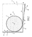
- la figure 7 est une vue partielle, schématique, agrandie et en coupe prise suivant le plan VII-VII de la figure 1,
- la figure 8 est une vue analogue à la figure 6 illustrant une variante de l'emballage de la figure 1,
- la figure 9 est une vue analogue à la figure 1 illustrant un emballage selon un deuxième mode de réalisation de l'invention, et
- la figure 10 est une vue schématique en plan d'un flan de carton pour former la caisse de l'emballage de la figure 9.
- FIG. 1 is a schematic perspective view of a closed package according to the invention,
- FIG. 2 is a schematic perspective view illustrating the box of the packaging of FIG. 1,
- FIG. 3 is a schematic plan view of a cardboard blank for forming the box of FIG. 2,
- FIG. 4 is a partial schematic view, enlarged and in section taken along line IV-IV of FIG. 3,
- FIG. 5 is a perspective view of the cover of the packaging of FIG. 1,
- FIG. 6 is a schematic plan view of a cardboard blank for forming the cover of FIG. 5,
- FIG. 7 is a partial, schematic view, enlarged and in section taken along the plane VII-VII of FIG. 1,
- FIG. 8 is a view similar to FIG. 6 illustrating a variant of the packaging of FIG. 1,
- FIG. 9 is a view similar to FIG. 1 illustrating a package according to a second embodiment of the invention, and
- FIG. 10 is a schematic plan view of a cardboard blank for forming the box of the packaging of FIG. 9.
La figure 1 illustre un emballage fermé 1 contenant un groupe de
récipients 2 dont seuls certains ont été représentés.Figure 1 illustrates a closed package 1 containing a group of
Ces récipients 2 sont par exemple des bouteilles de bière.These
L'emballage fermé 1 comprend une caisse 3 recouverte par une
coiffe 4.The closed packaging 1 comprises a box 3 covered by a
La caisse 3, illustrée plus particulièrement par la figure 2, a été obtenue
à partir d'un flan de carton 6, préalablement découpé et muni de raines, et
illustré par la figure 3.Box 3, more particularly illustrated in Figure 2, was obtained
from a blank of
Ce flan 6 est symétrique par rapport à un axe médian transversal, qui est vertical sur la figure 3.This blank 6 is symmetrical with respect to a transverse median axis, which is vertical in Figure 3.
Le flan 6 comprend un panneau de paroi inférieure 8 rectangulaire
prolongé au niveau de ses grands côtés par un panneau de paroi latérale 10 et
par un panneau de paroi latérale 12, qui est de hauteur plus réduite que le panneau
10.The blank 6 comprises a rectangular
Les panneaux 10 et 12 sont reliés au panneau de paroi inférieure 8
par des lignes de découpe 14 fortement interrompues qui forment lignes de
pliage. Ces lignes 14 sont horizontales (comme vu sur la figure 3).The
Le panneau 10 est prolongé au niveau de ses petits côtés, c'est-à-dire
vers la droite et vers la gauche sur la figure 3, par des volets 16 en forme de
trapèze rectangle. Chaque volet 16 est relié au panneau 10 par une ligne de
pliage 18 verticale (comme vu sur la figure 3).The
Le panneau 12 est prolongé au niveau de ses petits côtés, c'est-à-dire
vers la droite et vers la gauche sur la figure 3, par des volets 20 en forme de
trapèze rectangle. Ces volets sont chacun reliés au panneau 12 par des lignes
de pliage 22 verticales (comme vu sur la figure 3). The
Le panneau de paroi inférieure 8 est prolongé au niveau de ses petits
côtés, c'est-à-dire vers la droite et vers la gauche sur la figure 3, par des
panneaux de parois latérales 24. Chaque panneau 24 est relié au panneau 8 par
une ligne de pliage 26 verticale (comme vu sur la figure 3).The
Une ligne de découpe médiane 28 fortement interrompue est ménagée
dans chaque panneau 24. Cette ligne 28 forme ligne de pliage. Elle est
parallèle à la ligne 26 et partage le panneau 24 en une première zone 30 adjacente
à la ligne 26 et qui est de forme rectangulaire, et en une deuxième zone 32
de forme convergeant vers l'extérieur du flan 6.A severely interrupted
Deux lignes de découpe interrompues 34 s'étendent longitudinalement
dans le panneau de paroi latérale 10 et dans les volets 16 adjacents. Les
lignes 34 comportent des rebroussements 35 à leurs extrémités longitudinales.Two interrupted
Les lignes 34 délimitent entre elles une première région 36 sous
forme d'une bande et dont les extrémités longitudinales 38 situées dans les volets
16 sont légèrement divergentes.The
Les extrémités 38 de la première région 36 s'étendent chacune sur
sensiblement la moitié de la longueur du volet 16 correspondant.The
Les rebroussements 35 sont orientés vers l'axe médian transversal
du flan 6 et vers l'extérieur de la première région 36.The
Un onglet 40 est également découpé dans le panneau de paroi latérale
10 pour être adjacent à la première région 36. Cet onglet 40 est délimité
par une des lignes de découpe 34 et par une autre ligne de découpe 42 courbe.A
Comme illustré par la figure 4, le flan 6 est réalisé en carton ondulé
comprenant une feuille plane 44, qui formera une face intérieure dans la caisse
3, une feuille cannelée 46 et une feuille plane 48, qui formera une face extérieure
dans la caisse 3.As illustrated in Figure 4, the blank 6 is made of corrugated cardboard
comprising a
La feuille cannelée 46 est située entre les deux feuilles planes 44 et
48. Typiquement, le grammage du carton du flan 6 est compris entre environ
350g/m2 et environ 500g/m2, par exemple d'environ 425g/m2.The
Le flan 6 comprend une bande de renfort 50 rectiligne qui s'étend
sur toute la longueur du panneau de paroi latérale 10 et des volets 16 adjacents.
Cette bande 50 s'étend dans la région 36 et donc sur toute sa longueur. La
bande 50 est disposée entre la feuille plane 44 et la feuille cannelée 46 du flan 6.
Cette bande 50 est par exemple réalisée en fibres de polypropylène enduites de
colle. Elle a été insérée entre la feuille plane 44 et la feuille cannelée 46 lors du
procédé de fabrication du carton du flan 6.The blank 6 comprises a straight reinforcing
Cette bande 50 est orthogonale à la direction dans laquelle les
cannelures 52 de la feuille cannelée 46 s'étendent.This
Pour former la caisse 3 de la figure 2 à partir du flan 6 de la figure
3, on plie les panneaux 10 et 12 par rapport au panneau de paroi inférieure 8
grâce aux lignes 14 jusqu'à ce qu'ils soient orthogonaux au panneau 8. On replie
ensuite les volets 16 et les volets 20 vers l'intérieur du panneau de paroi inférieure.To form the box 3 of figure 2 from the blank 6 of figure
3, the
On fait ensuite pivoter les panneaux de parois latérales 24 pour
qu'ils soient orthogonaux au panneau de paroi inférieure 8. On colle ensuite les
volets 16 et 20 par leurs faces extérieures sur les faces intérieures des premières
zones 30 des panneaux des parois latérales 24.The
La caisse 3 ainsi obtenue comprend une paroi inférieure ou fond 8,
deux grandes parois latérales opposées 10 et 12 et deux petites parois latérales
opposées 54. Les parois 54 sont formées chacune par un panneau 24 et les volets
16 et 20 correspondants. Les parois latérales 10, 12 et 54 forment une ceinture
56 s'étendant continûment sur tout le pourtour du fond 8.The body 3 thus obtained comprises a bottom wall or bottom 8,
two large
Les parois latérales 10, 12 et 54 et le fond 8 délimitent ensemble
quatre trièdres situés chacun dans un angle du fond 8. En particulier, les parois
8, 10 et 54 définissent deux trièdres T1 et T2 situés en avant sur la figure 2.The
Les parois latérales 10, 12 et 54 sont venues de matière avec la paroi
inférieure 8 le long des lignes de pliage 14 et 26. Les parois latérales 54 sont
venues de matière d'une part avec la paroi latérale 10 le long des lignes de
pliage 18, et d'autre part avec la paroi latérale 12 le long des lignes de pliage 22.The
Ainsi, les parois latérales 10, 12 et 54 et la paroi inférieure 8 sont
reliées rigidement les unes aux autres.Thus, the
La coiffe 4, illustrée plus particulièrement par la figure 5, est obtenue
à partir d'un flan de carton 60, préalablement découpé et muni de raines et
illustré par la figure 6.The
Le flan 60 est symétrique par rapport à un axe longitudinal médian orienté verticalement sur la figure 6.The blank 60 is symmetrical with respect to a median longitudinal axis oriented vertically in Figure 6.
Le flan 60 comprend un panneau de paroi supérieure 62 rectangulaire
prolongé au niveau de ses grands côtés, c'est-à-dire vers le haut et vers le
bas sur la figure 6, par des panneaux de parois inclinées 64, puis par deux panneaux
de parois latérales respectivement 66 et 67, et enfin par deux rabats 68.The blank 60 includes a rectangular
Les panneaux de parois inclinées 64 sont reliés au panneau 62 par
deux lignes de pliage 70 horizontales (comme vu sur la figure 6). Ces panneaux
64 sont en forme de trapèze isocèle divergeant vers l'extérieur du flan 60.The
Les panneaux de parois latérales 66 et 67 sont reliés par deux lignes
de pliage 72 horizontales (comme vu sur la figure 6) aux panneaux 64. Les
panneaux 66 et 67 sont rectangulaires.The
Les rabats 68 sont reliés aux panneaux de parois latérales 66 et 67
par des lignes de découpe interrompues 74 formant lignes de pliage. Ces lignes
74 sont horizontales sur la figure 6. Les rabats 68 sont légèrement convergents
vers l'extérieur du flan 60.The
Les panneaux 64 sont prolongés vers la droite et vers la gauche sur
la figure 6, c'est-à-dire au niveau de leurs bords inclinés, par des volets 76 de
forme sensiblement triangulaire. Chaque volet 76 est relié au panneau 64
correspondant par une ligne de pliage 78 oblique.The
Le panneau de paroi supérieure 62 est prolongé au niveau de ses
petits côtés, c'est-à-dire vers la droite et vers la gauche sur la figure 6, par des
rabats 80 en forme de trapèze isocèle divergeant vers l'extérieur.The
Ces rabats 80 sont reliés au panneau de paroi supérieure 62 par
des lignes de pliage 82 verticales (comme vu sur la figure 6).These
Enfin, des découpes sont prévues dans le panneau 62 pour y délimiter
un losange 84 destiné à être déchiré, après enfoncement de deux onglets
86 découpés dans les rabats 80 et situés dans des angles opposés du losange
84, pour permettre d'accéder aux récipients 2 recouverts par la coiffe 4 dans
l'emballage 1.Finally, cutouts are provided in
Le flan 60 est symétrique par rapport à un axe médian transversal, orienté horizontalement sur la figure 6, sauf pour ce qui va être décrit par la suite.The blank 60 is symmetrical with respect to a transverse median axis, oriented horizontally in Figure 6, except for what will be described later.
Deux lignes de découpe interrompues 88 longitudinales sont ménagées
dans le panneau de paroi latérale 67 (en bas sur la figure 6).Two interrupted
Deux courtes lignes de découpe interrompues 90 transversales relient
les lignes 88, à faible distance de leurs extrémités 92. Les lignes 88 et 90
délimitent entre elles une deuxième région 94 en forme de bande et dont les extrémités
sont divergentes. Cette deuxième région 94 est prolongée à ses extrémités
par des volets 96 délimités par les extrémités 92 des lignes 88 et par les
lignes 90. Ces volets 96 sont articulés au reste du panneau de paroi latérale 67
par des lignes de pliage 97 verticales (comme vu sur la figure 6).Two short interrupted 90 transverse cutting lines connect
Un onglet 98 est découpé dans le panneau 67 au voisinage de la
deuxième région 94. Cet onglet 96 est délimité par une des deux lignes 88 et par
une ligne de découpe 99 courbe. Cet onglet 98 est adjacent à la deuxième région
94.A
Le carton utilisé pour former le flan 60 est un carton compact, c'est-à-dire
non-ondulé. Ainsi, ce carton 60 comprend par exemple plusieurs couches
ou feuilles planes superposées.The cardboard used to form the blank 60 is a compact cardboard, that is to say
non-corrugated. Thus, this
Typiquement, le carton utilisé pour le flan 60 a un grammage compris entre environ 250g/m2 et environ 400g/m2 et par exemple d'environ 360g/m2.Typically, the cardboard used for the blank 60 has a basis weight between about 250g / m 2 and about 400g / m 2 and for example about 360 g / m 2.
Pour former la coiffe 4, on fait pivoter, grâce aux lignes de pliage 70
et 72, les panneaux de parois inclinées 64 et les panneaux de parois latérales 66
et 67 vers le bas par rapport au panneau de paroi supérieure 62.To form the
On replie ensuite les volets 76 vers l'intérieur du panneau de paroi
supérieure 62 grâce aux lignes de pliage 78. On fait ensuite pivoter les rabats 80
vers le bas grâce aux lignes de pliage 82, puis on colle les volets 76 par leurs
faces externes sur la face interne des rabats 80.The
Les rabats d'extrémité 68 sont repliés vers l'intérieur du panneau de
parois supérieures 62 grâce aux lignes de pliage 74.The end flaps 68 are folded towards the inside of the panel.
Ainsi, les rabats 68 sont sensiblement parallèles à la paroi supérieure
62 et les parois latérales 66 et 67 sont sensiblement orthogonales à la paroi
supérieure 62. Les parois 64 et les rabats 80 sont inclinées d'un angle inférieur
à 90° par rapport à la paroi supérieure 62.Thus, the
Dans l'emballage 1 de la figure 1, les récipients 2 sont disposés
dans la caisse 3 et prennent appui sur sa paroi inférieure 8 par leurs fonds ou
extrémités inférieures.In the packaging 1 of FIG. 1, the
Les récipients 2 prennent appui sur la paroi supérieure 62 de la
coiffe 4 par leurs goulots ou extrémités supérieures.The
La caisse 3 et la coiffe 4 sont fixées l'une à l'autre par :
- collage des rabats 68 de la coiffe 4 sous la paroi inférieure 8 de la caisse 3,
- collage des rabats 80 de la coiffe 4 sur les deuxièmes
zones 32 des parois latérales 54 de la caisse 3,ces zones 32 étant repliées légèrement vers l'intérieur de la caisse 3, grâce aux lignes de pliage 28 (figure 2), pour suivre l'inclinaison des rabats 80, - collage de la paroi latérale 66 de la coiffe 4 sur la paroi latérale 12 de la caisse 3, et
- collage de la paroi latérale 67 de la coiffe 4 sur la paroi latérale 10 de la caisse 3.
- bonding of the
flaps 68 of thecover 4 under thelower wall 8 of the box 3, - bonding of the
flaps 80 of thecover 4 on thesecond zones 32 of theside walls 54 of the box 3, thesezones 32 being folded slightly towards the inside of the box 3, thanks to the fold lines 28 (FIG. 2), to follow the inclination of theflaps 80, - bonding of the
side wall 66 of thecover 4 on theside wall 12 of the box 3, and - bonding of the
side wall 67 of thecover 4 on theside wall 10 of the box 3.
Plus précisément, la paroi latérale 67 de la coiffe 4 est collée à la
paroi latérale 10 de la caisse 3 d'une part sous les première et deuxième régions
36 et 94, et d'autre part au dessus de ces régions 36 et 94. Un collage est également
assuré entre les régions 36 et 94 qui se chevauchent, la deuxième région
94 ayant des dimensions supérieures à celles de la première région 36 comme
on le voit sur la figure 1.More specifically, the
Quand un consommateur enfonce les onglets 98 et 40 qui se chevauchent
également, il peut saisir la première région 36 de la caisse 3 et la
deuxième région 94 de la coiffe 4 et les tirer vers l'extérieur. Le panneau latéral
10 de la caisse 3 (figure 2) se rompt alors le long des lignes 34 et le panneau
latéral 67 de la coiffe 4 (figure 5) se rompt le long des lignes de découpe 88 et
90.When a consumer presses overlapping
La deuxième région 94 se détache alors du reste du panneau 67 et
suit la première région 36 vers l'extérieur de l'emballage 1. Les régions 36 et 94
forment alors une poignée de saisie 100 (figure 1) en saillie par rapport au reste
de l'emballage 1.The
Comme on le voit sur la figure 7 pour l'extrémité 38 gauche de la
première région 36 de la poignée 100, les extrémités 38 épousent alors en partie
les parois latérales 102 des récipients 2 disposés dans les coins ou trièdres
avant T1 et T2 (figure 2) de la caisse 3. Cela est obtenu grâce au fait que les
extrémités 38 de la première région 36 s'étendent dans les parois 54 vers
l'arrière au-delà des axes longitudinaux A des récipients 2 placés dans les coins
T1 et T2.As seen in Figure 7 for the
Ainsi, quand un effort de traction est exercé sur la poignée 100, ces
extrémités 38 sont appliquées contre les parois latérales 102 des récipients 2
situés dans les coins T1 et T2 et tendent à les repousser vers l'intérieur de
l'emballage 1.Thus, when a tensile force is exerted on the
On a constaté que l'emballage 1 résiste particulièrement bien aux opérations de saisie de la poignée 100 et de transport.It has been found that the packaging 1 is particularly resistant to handle 100 and transport operations.
Cela est notamment dû aux caractéristiques suivantes ;
- présence d'un organe de renfort 50 intégré au carton de la caisse 3,
- découpage de la première région 36 dans trois panneaux latéraux 10 et 54 adjacents de la caisse 3, ces trois panneaux étant liés rigidement les uns aux autres et à la paroi inférieure 8 de la caisse 3,
- utilisation d'un carton ondulé et donc résistant pour former la caisse 3,
- coopération des extrémités 38 de la poignée 100 avec les récipients 2 situés dans les coins T1 et T2 de la caisse 3, cette coopération limitant les concentrations de contraintes,
- présence de rebroussements 35 prévus aux extrémités des lignes de découpe 34 délimitant la première région 36 dans la caisse 3,
- utilisation d'une caisse 3 comprenant une ceinture de parois latérales 56 bordant latéralement les récipients 2 sur tout le pourtour de la paroi inférieure 8 de la caisse 3.
- presence of a reinforcing
member 50 integrated into the carton of the box 3, - cutting of the
first region 36 in threeside panels bottom wall 8 of the body 3, - use of corrugated and therefore resistant cardboard to form the box 3,
- cooperation of the
ends 38 of thehandle 100 with thecontainers 2 located in the corners T1 and T2 of the body 3, this cooperation limiting the concentrations of stresses, - presence of
cusps 35 provided at the ends of thecutting lines 34 delimiting thefirst region 36 in the body 3, - use of a box 3 comprising a belt of
side walls 56 laterally bordering thecontainers 2 around the entire periphery of thebottom wall 8 of the box 3.
On notera que ces caractéristiques peuvent être utilisées indépendamment les unes des autres pour accroítre la résistance de l'emballage 1.Note that these characteristics can be used independently from each other to increase the resistance of the packaging 1.
En ce qui concerne la coopération des extrémités 38 de la poignée
100 avec les récipients 2, on notera que cette caractéristique peut être obtenue
sans que les extrémités 38 s'étendent dans les parois 54 au-delà des axes longitudinaux
A des récipients 2. C'est en particulier le cas lorsque les récipients ont
une section différente de la section circulaire représentée sur la figure 7, par
exemple une section polygonale. Il suffit alors que les extrémités 38 s'étendent
suffisamment dans les parois latérales 54 pour venir, lorsqu'un consommateur
saisit la poignée, s'appliquer contre les parois latérales 102 des récipients 2 disposés
dans les coins T1 et T2.Regarding the cooperation of the
En outre, l'emballage 1 induit des coûts réduits. Cela est dû notamment aux caractéristiques suivantes :
- utilisation d'un matériau moins résistant et moins coûteux pour la coiffe 4 que pour la caisse 3, la caisse 3 assurant la majorité de la reprise des efforts lors des opérations de saisie de la poignée 100 et de transport de l'emballage 1,
- intégration de la bande de renfort 50 dans le carton de la caisse 3 lors du procédé de fabrication de ce carton et non dans une étape ultérieure de fabrication de l'emballage 1,
- réalisation de l'emballage 1 en deux parties distinctes initialement séparées.
- use of a less resistant and less expensive material for the
cover 4 than for the box 3, the box 3 ensuring the majority of the recovery of forces during operations for gripping thehandle 100 and transporting the packaging 1, - integration of the reinforcing
strip 50 into the cardboard box 3 during the manufacturing process of this cardboard and not in a subsequent step of manufacturing the packaging 1, - realization of the packaging 1 in two distinct parts initially separated.
Plus précisément, l'emballage 1 étant réalisé en deux parties distinctes
3 et 4, on peut fournir les flans 6 et 60 correspondants à plat à une société
possédant une machine de mise en volume de ces flans. En raison de la taille
réduite de ces flans, une telle machine est simple et de coût réduit.More specifically, the packaging 1 being produced in two
Par ailleurs, les flans 6 sont moins coûteux à conditionner et à livrer
que les fourreaux de l'état de la technique qui nécessitent un conditionnement
particulier en caisse.Furthermore, the
Au contraire, les flans 6 et 60 peuvent être stockés sur des palettes
en sortie des machines de découpe et d'impression de flans 6 et 60.On the contrary, the
Les coûts logistiques liés à l'emballage 1 sont donc réduits.The logistics costs associated with packaging 1 are therefore reduced.
On notera que d'autres couples de matériaux qu'un carton ondulé
et un carton compact permettent de réduire le coût global de l'emballage 1 en
utilisant un matériau moins coûteux pour la coiffe 4 que pour la caisse 3.Note that other pairs of materials than corrugated cardboard
and a compact carton reduce the overall cost of packaging 1 by
using a less expensive material for the
Ainsi, l'emballage 1 permet de conditionner à faibles coûts un nombre
important de bouteilles de bières. Typiquement, l'emballage 1 permet de
conditionner un groupe de vingt quatre bouteilles 2 réparties en quatre rangées
de six bouteilles.Thus, the packaging 1 makes it possible to condition at low cost a number
important beer bottles. Typically, the packaging 1 makes it possible to
condition a group of twenty four
La figure 8 illustre une variante de l'emballage 1 de la figure 1 dans
laquelle les volets 76 de la coiffe 3 sont reliés aux rabats 80 par des lignes de
pliage 103 obliques. Chaque volet 76 est partagé en deux par une ligne de
pliage 104 oblique. Les volets 76 forment ainsi des goussets que l'on replie à
l'intérieur de la coiffe 3 et que l'on colle sur les rabats 80 pour atteindre la structure
des figures 1 et 5. FIG. 8 illustrates a variant of the packaging 1 of FIG. 1 in
which the
Dans une autre variante non représentée, la paroi supérieure 62 de
la coiffe 3 comprend un réseau d'ouvertures de passage des extrémités supérieures
des récipients 2.In another variant not shown, the
Les figures 9 et 10 illustrent un deuxième mode de réalisation de
l'invention selon lequel la poignée 100 est prévue sur une petite paroi latérale 54
de la caisse 3 et non plus sur la paroi latérale 10 de la caisse 3 et sur la paroi
latérale 67 de la coiffe 4.Figures 9 and 10 illustrate a second embodiment of
the invention according to which the
Ainsi, et comme on le voit sur la figure 10, le flan 6 utilisé pour former
la caisse 3 ne comprend plus de volets 16 et 20.Thus, and as seen in FIG. 10, the blank 6 used to form
box 3 no longer includes
En revanche, les panneaux de parois latérales 24 sont prolongés
au niveau de leurs petits côtés, c'est-à-dire vers le haut et vers le bas sur la figure
10, par des volets 105 en forme de trapèze rectangle.On the other hand, the
Ces volets 105 sont reliés chacun au panneau 24 correspondant
par une ligne de pliage 106 horizontale sur la figure 10.These
La première région 36, et donc les lignes de découpe interrompues
34, s'étendent transversalement dans le panneau 24 droit (comme vu sur la figure
10) et dans les volets 105 correspondants. De même, l'onglet 40 est ménagé
dans le même panneau 24.The
Dans ce mode de réalisation, et comme on le voit sur la figure 9, la
poignée 100 est formée simplement par la première région 36. On notera que la
coiffe 4 ne comporte plus de deuxième région 94.In this embodiment, and as seen in FIG. 9, the
On notera également que l'orientation des cannelures du carton du
flan 6 a été modifiée par rapport à celle de la figure 3, de manière à assurer que
l'organe de renfort 50 soit orthogonal à la direction selon laquelle les cannelures
s'étendent.It will also be noted that the orientation of the cardboard grooves of the
blank 6 has been modified from that in Figure 3, so as to ensure that
the reinforcing
Dans ce mode de réalisation, les extrémités 38 de la poignée 100
coopèrent avec les récipients 2 disposés dans les coins droits de la caisse 3,
comme décrit précédemment.In this embodiment, the ends 38 of the
Ainsi, l'emballage selon le deuxième mode de réalisation permet
également de conditionner un nombre important de récipients 2 avec des coûts
réduits.Thus, the packaging according to the second embodiment allows
also to package a large number of
Typiquement, le nombre de récipients 2 que l'emballage 1 selon ce
deuxième mode de réalisation peut conditionner est inférieur à celui que
l'emballage des figures 1 à 8 peut conditionner. Ainsi, l'emballage 1 selon le
deuxième mode de réalisation peut conditionner un groupe de douze bouteilles
2.Typically, the number of
Claims (13)
- Closed packaging case (1) for packaging a set of containers (2), of the type comprising a part forming the base (3), a part forming the lid (4) separate from the part forming the base (3) and fixed thereto, and a handle (100) comprising at least one first region (36) cut out in a first one (3) of the parts, characterised in that the first part (3) comprises an end wall (8) on which ends of the containers (2) are adapted to bear, and a belt (56) of side walls extending all round the circumference of the end wall (8) in order to confine the containers (2) at the sides, and in that the first part (3) is made of a different material from the second one (4) of the parts.
- Packaging case according to claim 1, characterised in that the first part ,(3) is made of corrugated cardboard and the second part is made of cardboard comprising (a) flat layer(s).
- Packaging case according to claim 1 or 2, characterised in that the second part (4) is made from a material with a lower weight per unit area than the first part (3).
- Packaging case according to claim 3, characterised in that the weight per unit area of the material of the first part (3) is between about 350 g/m2 and 500 g/m2 and the weight per unit area of the material of the second part (4) is between about 250 g/m2 and 400 g/m2.
- Packaging case according to one of the preceding claims , characterised in that the first part (3) is the part forming the base, the lower ends of the containers (2) being adapted to bear on the end wall (8).
- Packaging case according to one of the preceding claims , characterised in that the belt of side walls comprises a central side wall (10; 54) and two adjacent side walls (54; 10, 12) extending the central side wall on both sides, the end wall (8) and the central side wall forming, with each adjacent side wall, a respective trihedron (T1, T2), in that the central wall (10; 54) is rigidly attached to the adjacent side walls (54; 10, 12) and the adjacent side walls (54; 10, 12) are rigidly attached to the end wall (8), and in that the first region extends in the central side wall (10; 54) and in the adjacent side walls (54; 10, 12).
- Packaging case according to claim 6, characterised in that the central side wall (10; 54) and the adjacent side walls (54; 10, 12) are integrally formed with the end wall (8) along fold lines.
- Packaging case according 10 claim 6 or 7, characterised in that the central side wall (10; 54) is integrally formed with the adjacent side walls (54; 10, 12) along fold lines.
- Packaging case according to claim 8, characterised in that the adjacent side walls (54; 10, 12) comprise flaps (16, 20; 104) integrally formed with the central side panel (10; 54) along fold lines, and panels (24) glued to the flaps.
- Packaging case according to one of claims 6 to 9, characterised in that the first region (36) extends sufficiently in at least one adjacent side wall (54; 10, 12) to come to bear on the side wall (102) of a container (2) placed in the trihedron (T1, T2) delimited by said adjacent side wall (54; 10, 12), by the central side wall (10; 54) and by the end wall (8), when a consumer grips the handle (100).
- Packaging case according, to claim 10, characterised in that the first region (36) extends in said adjacent side wall (54; 10, 12) beyond a central longitudinal axis (A) along which the said container (2) extends between its lower end and its upper end.
- Packaging case according to one of the preceding claims, characterised in that the first part is the part forming the base (3), the lower ends of the containers (2) being adapted to bear on the end wall (8).
- Unit comprising two blanks (6, 60) cut to shape and provided with fold lines for allowing assembly into a part forming the base (3) and a part forming the lid (4), respectively, of a closed packaging case for packaging a set of containers (2), the unit comprising a handle (100) having a first region (36) cut out in a first one of the blanks, characterised in that the unit is adapted to form a packaging case according to one of the preceding claims, the two blanks being made from different materials and the first blank being adapted to provide an end wall (8) on which ends of the containers are adapted to bear, and a belt (56) of side walls extending all round the circumference of the end wall in order to confine the containers at the sides.
Applications Claiming Priority (2)
| Application Number | Priority Date | Filing Date | Title |
|---|---|---|---|
| FR0109681A FR2827582B1 (en) | 2001-07-19 | 2001-07-19 | CLOSED PACKAGE WITH BODY AND HATCHET MADE OF DIFFERENT MATERIALS AND ASSEMBLY CORRESPONDING FROM TWO BLANKS |
| FR0109681 | 2001-07-19 |
Publications (2)
| Publication Number | Publication Date |
|---|---|
| EP1279618A1 EP1279618A1 (en) | 2003-01-29 |
| EP1279618B1 true EP1279618B1 (en) | 2004-09-22 |
Family
ID=8865716
Family Applications (1)
| Application Number | Title | Priority Date | Filing Date |
|---|---|---|---|
| EP02291655A Expired - Lifetime EP1279618B1 (en) | 2001-07-19 | 2002-07-02 | Closed packaging case and lid made of different materials |
Country Status (5)
| Country | Link |
|---|---|
| EP (1) | EP1279618B1 (en) |
| AT (1) | ATE276932T1 (en) |
| DE (1) | DE60201306T2 (en) |
| ES (1) | ES2227405T3 (en) |
| FR (1) | FR2827582B1 (en) |
Families Citing this family (2)
| Publication number | Priority date | Publication date | Assignee | Title |
|---|---|---|---|---|
| CA2490134A1 (en) * | 2002-06-26 | 2004-01-08 | Meadwestvaco Packaging Systems Llc | Carton and carton blank |
| ES2439241T3 (en) * | 2006-04-04 | 2014-01-22 | Graphic Packaging International, Inc. | Cardboard container with distributor |
Family Cites Families (5)
| Publication number | Priority date | Publication date | Assignee | Title |
|---|---|---|---|---|
| US4295598A (en) * | 1980-06-20 | 1981-10-20 | The Mead Corporation | Carton with carrying strap |
| FR2508415A1 (en) * | 1981-06-26 | 1982-12-31 | Gervais Danone Co | Precut folded blank for bottle pack - has perpendicular grid fold lines with joint flaps and bonded plastics strip on centre bottle row |
| GB2186550B (en) * | 1986-09-17 | 1990-05-23 | St Regis Packaging Ltd | Improvements in packaging |
| US4715493A (en) * | 1986-10-27 | 1987-12-29 | Icp S.A. | Composite package for a group of containers |
| FR2707260B1 (en) | 1993-07-09 | 1996-10-04 | 4 P Emballages France | Closed packaging for an ordered group of objects such as beverage containers. |
-
2001
- 2001-07-19 FR FR0109681A patent/FR2827582B1/en not_active Expired - Fee Related
-
2002
- 2002-07-02 ES ES02291655T patent/ES2227405T3/en not_active Expired - Lifetime
- 2002-07-02 EP EP02291655A patent/EP1279618B1/en not_active Expired - Lifetime
- 2002-07-02 AT AT02291655T patent/ATE276932T1/en not_active IP Right Cessation
- 2002-07-02 DE DE60201306T patent/DE60201306T2/en not_active Expired - Fee Related
Also Published As
| Publication number | Publication date |
|---|---|
| FR2827582B1 (en) | 2004-06-18 |
| DE60201306T2 (en) | 2005-10-06 |
| ATE276932T1 (en) | 2004-10-15 |
| ES2227405T3 (en) | 2005-04-01 |
| DE60201306D1 (en) | 2004-10-28 |
| FR2827582A1 (en) | 2003-01-24 |
| EP1279618A1 (en) | 2003-01-29 |
Similar Documents
| Publication | Publication Date | Title |
|---|---|---|
| EP0846070B1 (en) | blank supplied in flat condition, and set into shape in two distinct phases and having extended adhesive effect for forming a container | |
| FR2500413A1 (en) | PACKAGING BOX OF A SET OF BOTTLE-SHAPED ARTICLES, DISPOSED IN TWO ROWS | |
| EP0977690A1 (en) | Package, assembly of blanks, method and device for packaging an articles or a group of articles of indefinite volume | |
| EP0225208B1 (en) | Package and method for packaging products in cling films | |
| EP1279618B1 (en) | Closed packaging case and lid made of different materials | |
| EP2352680B1 (en) | Method for making a corrugated cardboard packaging crate | |
| EP1279617B1 (en) | Closed package as rigid crate and corresponding assembly of two blanks | |
| EP0765823A1 (en) | Container for bicycles | |
| FR2800714A1 (en) | Rectangular carton for displaying or carrying sets of three bottles is folded from conventional blank whose longer sides have flaps whose ends are glued to opposite wall when carton is assembled to form separators between bottles | |
| FR2792290A1 (en) | Set of blanks for construction of folding crate form tray and lid and crate has transverse side wall which may be manually torn from remainder of crate | |
| EP0669257B1 (en) | Carton or the like, in particular for jars for dairy products, as well as a blank for producing the same | |
| FR2827583A1 (en) | Carton for bottles of beer has handle which fits through slots in top, top being made up of several layers and handle containing reinforcing strip | |
| EP0978371B1 (en) | Method of reinforcing the load carrying sidewalls of trays of corrugated cardboard and tray so obtained | |
| FR2780703A1 (en) | Package made from semi rigid material for diverse items | |
| EP2829486B1 (en) | Packaging comprising a semi-rigid material and a heat-shrinkable film, blank and method of manufacture | |
| FR2965553A1 (en) | Slotted type package box for receiving, transporting and protecting wine bottles, has extension panel positioned at proximity of hinge with side panel to be integrated near free edge of another side panel after folding package | |
| FR2778635A1 (en) | Cardboard packaging transformable into display shelf | |
| FR2733740A1 (en) | Package for grouped objects, e.g. containers of drink, made from two or more cardboard panels and interlocking elements | |
| FR2726537A1 (en) | Cardboard packaging container for bottles or similar elongate objects | |
| FR2854136A1 (en) | Article package, has film articulated on one part of flap by folding line, such that flap swivels and retracts under solicitation of flaps overlapping part, where film is solicited towards interior for freeing film from flap | |
| FR2818616A1 (en) | Tray for food or vegetables has sloping sides, shorter sides being higher than longer ones, and is produced from conventional blank, but made from fiber board covered on outside with paper or plastic rather than cardboard | |
| FR2862615A1 (en) | Stackable tray for e.g. yogurt package, has two opposed lateral walls each comprising flap provided with longitudinal flap to form bead on top part of former flap, and recess situated under bead, where tray is made of cardboard | |
| FR2615483A1 (en) | Package with heat shrink film | |
| FR3135257A1 (en) | Transportable and stackable packaging | |
| FR3102156A1 (en) | Packaging incorporating an element for separating and / or wedging bottles |
Legal Events
| Date | Code | Title | Description |
|---|---|---|---|
| PUAI | Public reference made under article 153(3) epc to a published international application that has entered the european phase |
Free format text: ORIGINAL CODE: 0009012 |
|
| AK | Designated contracting states |
Designated state(s): AT BE BG CH CY CZ DE DK EE ES FI FR GB GR IE IT LI LU MC NL PT SE SK TR |
|
| AX | Request for extension of the european patent |
Extension state: AL LT LV MK RO SI |
|
| 17P | Request for examination filed |
Effective date: 20030404 |
|
| AKX | Designation fees paid |
Designated state(s): AT BE BG CH CY CZ DE DK EE ES FI FR GB GR IE IT LI LU MC NL PT SE SK TR |
|
| 17Q | First examination report despatched |
Effective date: 20031009 |
|
| GRAP | Despatch of communication of intention to grant a patent |
Free format text: ORIGINAL CODE: EPIDOSNIGR1 |
|
| GRAS | Grant fee paid |
Free format text: ORIGINAL CODE: EPIDOSNIGR3 |
|
| GRAA | (expected) grant |
Free format text: ORIGINAL CODE: 0009210 |
|
| AK | Designated contracting states |
Kind code of ref document: B1 Designated state(s): AT BE BG CH CY CZ DE DK EE ES FI FR GB GR IE IT LI LU MC NL PT SE SK TR |
|
| PG25 | Lapsed in a contracting state [announced via postgrant information from national office to epo] |
Ref country code: IT Free format text: LAPSE BECAUSE OF FAILURE TO SUBMIT A TRANSLATION OF THE DESCRIPTION OR TO PAY THE FEE WITHIN THE PRESCRIBED TIME-LIMIT;WARNING: LAPSES OF ITALIAN PATENTS WITH EFFECTIVE DATE BEFORE 2007 MAY HAVE OCCURRED AT ANY TIME BEFORE 2007. THE CORRECT EFFECTIVE DATE MAY BE DIFFERENT FROM THE ONE RECORDED. Effective date: 20040922 Ref country code: SK Free format text: LAPSE BECAUSE OF FAILURE TO SUBMIT A TRANSLATION OF THE DESCRIPTION OR TO PAY THE FEE WITHIN THE PRESCRIBED TIME-LIMIT Effective date: 20040922 Ref country code: CZ Free format text: LAPSE BECAUSE OF FAILURE TO SUBMIT A TRANSLATION OF THE DESCRIPTION OR TO PAY THE FEE WITHIN THE PRESCRIBED TIME-LIMIT Effective date: 20040922 Ref country code: FI Free format text: LAPSE BECAUSE OF FAILURE TO SUBMIT A TRANSLATION OF THE DESCRIPTION OR TO PAY THE FEE WITHIN THE PRESCRIBED TIME-LIMIT Effective date: 20040922 Ref country code: AT Free format text: LAPSE BECAUSE OF FAILURE TO SUBMIT A TRANSLATION OF THE DESCRIPTION OR TO PAY THE FEE WITHIN THE PRESCRIBED TIME-LIMIT Effective date: 20040922 Ref country code: TR Free format text: LAPSE BECAUSE OF FAILURE TO SUBMIT A TRANSLATION OF THE DESCRIPTION OR TO PAY THE FEE WITHIN THE PRESCRIBED TIME-LIMIT Effective date: 20040922 Ref country code: EE Free format text: LAPSE BECAUSE OF FAILURE TO SUBMIT A TRANSLATION OF THE DESCRIPTION OR TO PAY THE FEE WITHIN THE PRESCRIBED TIME-LIMIT Effective date: 20040922 Ref country code: IE Free format text: LAPSE BECAUSE OF FAILURE TO SUBMIT A TRANSLATION OF THE DESCRIPTION OR TO PAY THE FEE WITHIN THE PRESCRIBED TIME-LIMIT Effective date: 20040922 Ref country code: BG Free format text: LAPSE BECAUSE OF FAILURE TO SUBMIT A TRANSLATION OF THE DESCRIPTION OR TO PAY THE FEE WITHIN THE PRESCRIBED TIME-LIMIT Effective date: 20040922 |
|
| REG | Reference to a national code |
Ref country code: GB Ref legal event code: FG4D Free format text: NOT ENGLISH |
|
| REG | Reference to a national code |
Ref country code: CH Ref legal event code: EP |
|
| REG | Reference to a national code |
Ref country code: IE Ref legal event code: FG4D Free format text: FRENCH |
|
| REF | Corresponds to: |
Ref document number: 60201306 Country of ref document: DE Date of ref document: 20041028 Kind code of ref document: P |
|
| PG25 | Lapsed in a contracting state [announced via postgrant information from national office to epo] |
Ref country code: DK Free format text: LAPSE BECAUSE OF FAILURE TO SUBMIT A TRANSLATION OF THE DESCRIPTION OR TO PAY THE FEE WITHIN THE PRESCRIBED TIME-LIMIT Effective date: 20041222 Ref country code: GR Free format text: LAPSE BECAUSE OF FAILURE TO SUBMIT A TRANSLATION OF THE DESCRIPTION OR TO PAY THE FEE WITHIN THE PRESCRIBED TIME-LIMIT Effective date: 20041222 Ref country code: SE Free format text: LAPSE BECAUSE OF FAILURE TO SUBMIT A TRANSLATION OF THE DESCRIPTION OR TO PAY THE FEE WITHIN THE PRESCRIBED TIME-LIMIT Effective date: 20041222 |
|
| GBT | Gb: translation of ep patent filed (gb section 77(6)(a)/1977) |
Effective date: 20050119 |
|
| REG | Reference to a national code |
Ref country code: ES Ref legal event code: FG2A Ref document number: 2227405 Country of ref document: ES Kind code of ref document: T3 |
|
| REG | Reference to a national code |
Ref country code: IE Ref legal event code: FD4D |
|
| PG25 | Lapsed in a contracting state [announced via postgrant information from national office to epo] |
Ref country code: CY Free format text: LAPSE BECAUSE OF FAILURE TO SUBMIT A TRANSLATION OF THE DESCRIPTION OR TO PAY THE FEE WITHIN THE PRESCRIBED TIME-LIMIT Effective date: 20050702 Ref country code: LU Free format text: LAPSE BECAUSE OF NON-PAYMENT OF DUE FEES Effective date: 20050702 |
|
| PLBE | No opposition filed within time limit |
Free format text: ORIGINAL CODE: 0009261 |
|
| STAA | Information on the status of an ep patent application or granted ep patent |
Free format text: STATUS: NO OPPOSITION FILED WITHIN TIME LIMIT |
|
| PG25 | Lapsed in a contracting state [announced via postgrant information from national office to epo] |
Ref country code: MC Free format text: LAPSE BECAUSE OF NON-PAYMENT OF DUE FEES Effective date: 20050731 |
|
| 26N | No opposition filed |
Effective date: 20050623 |
|
| PG25 | Lapsed in a contracting state [announced via postgrant information from national office to epo] |
Ref country code: CH Free format text: LAPSE BECAUSE OF NON-PAYMENT OF DUE FEES Effective date: 20060731 Ref country code: LI Free format text: LAPSE BECAUSE OF NON-PAYMENT OF DUE FEES Effective date: 20060731 |
|
| REG | Reference to a national code |
Ref country code: FR Ref legal event code: CL |
|
| REG | Reference to a national code |
Ref country code: CH Ref legal event code: PL |
|
| PGFP | Annual fee paid to national office [announced via postgrant information from national office to epo] |
Ref country code: DE Payment date: 20070711 Year of fee payment: 6 |
|
| PGFP | Annual fee paid to national office [announced via postgrant information from national office to epo] |
Ref country code: ES Payment date: 20070717 Year of fee payment: 6 |
|
| REG | Reference to a national code |
Ref country code: FR Ref legal event code: TP |
|
| PG25 | Lapsed in a contracting state [announced via postgrant information from national office to epo] |
Ref country code: PT Free format text: LAPSE BECAUSE OF NON-PAYMENT OF DUE FEES Effective date: 20050222 |
|
| PGFP | Annual fee paid to national office [announced via postgrant information from national office to epo] |
Ref country code: GB Payment date: 20070710 Year of fee payment: 6 |
|
| PGFP | Annual fee paid to national office [announced via postgrant information from national office to epo] |
Ref country code: BE Payment date: 20070801 Year of fee payment: 6 Ref country code: NL Payment date: 20070618 Year of fee payment: 6 |
|
| PGFP | Annual fee paid to national office [announced via postgrant information from national office to epo] |
Ref country code: FR Payment date: 20070426 Year of fee payment: 6 |
|
| GBPC | Gb: european patent ceased through non-payment of renewal fee |
Effective date: 20080702 |
|
| NLV4 | Nl: lapsed or anulled due to non-payment of the annual fee |
Effective date: 20090201 |
|
| PG25 | Lapsed in a contracting state [announced via postgrant information from national office to epo] |
Ref country code: DE Free format text: LAPSE BECAUSE OF NON-PAYMENT OF DUE FEES Effective date: 20090203 |
|
| REG | Reference to a national code |
Ref country code: FR Ref legal event code: ST Effective date: 20090331 |
|
| PG25 | Lapsed in a contracting state [announced via postgrant information from national office to epo] |
Ref country code: NL Free format text: LAPSE BECAUSE OF NON-PAYMENT OF DUE FEES Effective date: 20090201 |
|
| PG25 | Lapsed in a contracting state [announced via postgrant information from national office to epo] |
Ref country code: GB Free format text: LAPSE BECAUSE OF NON-PAYMENT OF DUE FEES Effective date: 20080702 |
|
| PG25 | Lapsed in a contracting state [announced via postgrant information from national office to epo] |
Ref country code: FR Free format text: LAPSE BECAUSE OF NON-PAYMENT OF DUE FEES Effective date: 20080731 |
|
| REG | Reference to a national code |
Ref country code: ES Ref legal event code: FD2A Effective date: 20080703 |
|
| PG25 | Lapsed in a contracting state [announced via postgrant information from national office to epo] |
Ref country code: ES Free format text: LAPSE BECAUSE OF NON-PAYMENT OF DUE FEES Effective date: 20080703 |
|
| PG25 | Lapsed in a contracting state [announced via postgrant information from national office to epo] |
Ref country code: BE Free format text: LAPSE BECAUSE OF NON-PAYMENT OF DUE FEES Effective date: 20080731 |