EP1433713B1 - Verpackung mit einer Hülle mit mindestens einem Behälterbefestigungelement - Google Patents
Verpackung mit einer Hülle mit mindestens einem Behälterbefestigungelement Download PDFInfo
- Publication number
- EP1433713B1 EP1433713B1 EP03292877A EP03292877A EP1433713B1 EP 1433713 B1 EP1433713 B1 EP 1433713B1 EP 03292877 A EP03292877 A EP 03292877A EP 03292877 A EP03292877 A EP 03292877A EP 1433713 B1 EP1433713 B1 EP 1433713B1
- Authority
- EP
- European Patent Office
- Prior art keywords
- containers
- flap
- lower wall
- packaging
- wall
- Prior art date
- Legal status (The legal status is an assumption and is not a legal conclusion. Google has not performed a legal analysis and makes no representation as to the accuracy of the status listed.)
- Expired - Lifetime
Links
- 238000004806 packaging method and process Methods 0.000 claims description 24
- 239000000853 adhesive Substances 0.000 abstract 1
- 230000001070 adhesive effect Effects 0.000 abstract 1
- 230000014759 maintenance of location Effects 0.000 description 7
- 235000013618 yogurt Nutrition 0.000 description 4
- 230000015572 biosynthetic process Effects 0.000 description 3
- 239000011229 interlayer Substances 0.000 description 2
- 125000006850 spacer group Chemical group 0.000 description 2
- 238000004026 adhesive bonding Methods 0.000 description 1
- 238000005452 bending Methods 0.000 description 1
- 210000004027 cell Anatomy 0.000 description 1
- 230000001419 dependent effect Effects 0.000 description 1
- 238000012423 maintenance Methods 0.000 description 1
- 238000004519 manufacturing process Methods 0.000 description 1
- 238000003856 thermoforming Methods 0.000 description 1
Images

Classifications
-
- B—PERFORMING OPERATIONS; TRANSPORTING
- B65—CONVEYING; PACKING; STORING; HANDLING THIN OR FILAMENTARY MATERIAL
- B65D—CONTAINERS FOR STORAGE OR TRANSPORT OF ARTICLES OR MATERIALS, e.g. BAGS, BARRELS, BOTTLES, BOXES, CANS, CARTONS, CRATES, DRUMS, JARS, TANKS, HOPPERS, FORWARDING CONTAINERS; ACCESSORIES, CLOSURES, OR FITTINGS THEREFOR; PACKAGING ELEMENTS; PACKAGES
- B65D71/00—Bundles of articles held together by packaging elements for convenience of storage or transport, e.g. portable segregating carrier for plural receptacles such as beer cans or pop bottles; Bales of material
- B65D71/06—Packaging elements holding or encircling completely or almost completely the bundle of articles, e.g. wrappers
- B65D71/12—Packaging elements holding or encircling completely or almost completely the bundle of articles, e.g. wrappers the packaging elements, e.g. wrappers being formed by folding a single blank
- B65D71/14—Packaging elements holding or encircling completely or almost completely the bundle of articles, e.g. wrappers the packaging elements, e.g. wrappers being formed by folding a single blank having the shape of a tube, without, or not being characterised by, end walls
- B65D71/16—Packaging elements holding or encircling completely or almost completely the bundle of articles, e.g. wrappers the packaging elements, e.g. wrappers being formed by folding a single blank having the shape of a tube, without, or not being characterised by, end walls with article-locating elements
-
- B—PERFORMING OPERATIONS; TRANSPORTING
- B65—CONVEYING; PACKING; STORING; HANDLING THIN OR FILAMENTARY MATERIAL
- B65D—CONTAINERS FOR STORAGE OR TRANSPORT OF ARTICLES OR MATERIALS, e.g. BAGS, BARRELS, BOTTLES, BOXES, CANS, CARTONS, CRATES, DRUMS, JARS, TANKS, HOPPERS, FORWARDING CONTAINERS; ACCESSORIES, CLOSURES, OR FITTINGS THEREFOR; PACKAGING ELEMENTS; PACKAGES
- B65D2571/00—Bundles of articles held together by packaging elements for convenience of storage or transport, e.g. portable segregating carrier for plural receptacles such as beer cans, pop bottles; Bales of material
- B65D2571/00123—Bundling wrappers or trays
- B65D2571/00648—Elements used to form the wrapper
- B65D2571/00654—Blanks
- B65D2571/0066—Blanks formed from one single sheet
-
- B—PERFORMING OPERATIONS; TRANSPORTING
- B65—CONVEYING; PACKING; STORING; HANDLING THIN OR FILAMENTARY MATERIAL
- B65D—CONTAINERS FOR STORAGE OR TRANSPORT OF ARTICLES OR MATERIALS, e.g. BAGS, BARRELS, BOTTLES, BOXES, CANS, CARTONS, CRATES, DRUMS, JARS, TANKS, HOPPERS, FORWARDING CONTAINERS; ACCESSORIES, CLOSURES, OR FITTINGS THEREFOR; PACKAGING ELEMENTS; PACKAGES
- B65D2571/00—Bundles of articles held together by packaging elements for convenience of storage or transport, e.g. portable segregating carrier for plural receptacles such as beer cans, pop bottles; Bales of material
- B65D2571/00123—Bundling wrappers or trays
- B65D2571/00709—Shape of the formed wrapper, i.e. shape of each formed element if the wrapper is made from more than one element
- B65D2571/00716—Shape of the formed wrapper, i.e. shape of each formed element if the wrapper is made from more than one element tubular without end walls
-
- B—PERFORMING OPERATIONS; TRANSPORTING
- B65—CONVEYING; PACKING; STORING; HANDLING THIN OR FILAMENTARY MATERIAL
- B65D—CONTAINERS FOR STORAGE OR TRANSPORT OF ARTICLES OR MATERIALS, e.g. BAGS, BARRELS, BOTTLES, BOXES, CANS, CARTONS, CRATES, DRUMS, JARS, TANKS, HOPPERS, FORWARDING CONTAINERS; ACCESSORIES, CLOSURES, OR FITTINGS THEREFOR; PACKAGING ELEMENTS; PACKAGES
- B65D2571/00—Bundles of articles held together by packaging elements for convenience of storage or transport, e.g. portable segregating carrier for plural receptacles such as beer cans, pop bottles; Bales of material
- B65D2571/00123—Bundling wrappers or trays
- B65D2571/00833—Other details of wrappers
- B65D2571/0087—Special features for machine processing, e.g. gripper apertures
Definitions
- the present invention relates to a package for packaging a group of at least two containers, the package being of the type comprising at least one longitudinally extending sheath and comprising an upper wall, a lower wall, two side walls connecting the lower walls and upper, and at least one container holding member, the holding member protruding from the bottom wall to be disposed between containers, the holding member comprising a shutter cut in the bottom wall and folded around a line bending, the flap being cut into the bottom wall of a first side of the fold line.
- the invention applies, for example, to the packaging of jars of yoghurt or compote.
- the sheath is made of cardboard and the bottom wall is formed of two half-walls fixed rune to another.
- the holding member is a beam which extends longitudinally between two rows of pots and which is formed from a shutter cut into the edge of a first of the lower half-walls.
- the flap is folded relative to the first half-bottom wall around a fold line and is attached to the other lower half-wall.
- the beam is located on the same side of the fold line as the one where the shutter was cut.
- Such a holding element structure requires using a lot of cardboard, and more than if the bottom wall was made in one piece.
- DE-39 28 076 also discloses a package comprising a sleeve with a holding beam which requires the use of a large amount of cardboard.
- An object of the invention is to solve this problem by providing a package of the aforementioned type in which the structure of the holding member can reduce the cost of packaging.
- the subject of the invention is a package according to claim 1.
- the package may comprise one or more of the features of the dependent claims.
- the invention also relates to an assembly according to claim 11.
- the invention further relates to a blank according to claim 12.
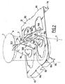
- FIG. 1 represents a set 1 comprising a group 2 of eight jars of yogurt 3 and a package 4.
- the pots 3 are identical, arranged vertically and have for example a generally frustoconical shape converging downwards. As illustrated for example in Figure 2, the pots 3 each have at their upper open end an annular rim 6 and a circular seal 7 closing this open end.
- pots 3 have been shown in phantom in Figures 1 and 2 and some pots 3 have not been shown for more visibility.
- the pots 3 are arranged in two superimposed levels, namely a lower level of four pots 3, and a top level of four pots 3.
- the pots 3 of the upper level each surmount a pot 3 of the lower level.
- the four pots 3 are regularly arranged in two rows 10 extending in a longitudinal direction L of the package 4.
- the package 4 comprises an outer sleeve 11 which externally envelops the group 2, and an insert 12 disposed between the lower level and the upper level of pots 3.
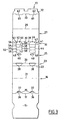
- the fold line 17 is interrupted by two cuts 35 formed in the right side wall 16. These cutouts 35 delimit two flanges 36 extending the upper wall 15 and two clearances 37 substantially rectangular.
- Two disc-shaped openings 38 are formed in the lower region 23 of the right-hand side wall 16.
- Two oblong slots 40 are formed substantially in the center of the bottom wall 25, facing the openings 38.
- Two cutouts 41 are formed in the lower region 31 of the left-hand lateral wall 27 and in the lower wall 25. These cut-outs 41 each comprise a section 42 in the shape of an arc in the region 31.
- the sections 42 have, for example, a corresponding shape. at the contour of the openings 38.
- the sections 42 are each extended by two curved end sections 44 which extend in the bottom wall 25 towards the slots 40.
- the cutouts 41 delimit two flaps 46 which are connected to the lower wall 25 by fold lines 48 which are each between the ends of the two sections 44 of the corresponding cut 41.
- Each flap 46 is thus cut on the left side (at the top in FIG. 3) of the corresponding fold line 48.
- Each flap 46 comprises from the fold line 48 corresponding four successive panels 50, 52, 54, 56 separated by longitudinal fold lines 58.
- the panel 56 farthest from the fold line 48 hereinafter referred to as an end panel, has a disk sector shape.
- the fold line 33 is interrupted by two cutouts 60 in U which delimit flanges 62 extending the fastening flap 32.
- the flaps 46 are folded from the side to the left of the fold lines 48 to the right side thereof.
- the end panels 56 are glued to the bottom wall 25 to the right of the fold lines 48 and beyond the oblong slots 40.
- the panels 50, 52, 54 and 56 are then folded relative to each other around the fold lines 58 substantially at right angles, as shown in FIG.
- Each flap 46 thus forms a beam 64 of substantially square section. Alternatively, this section may be rectangular.
- the beam 64 is located to the right of the fold line 48 corresponding, while the flap 46 has been cut to the left of this fold line 48.
- the side walls 16 and 27 are bent upwards with respect to the bottom wall 25.
- the formation of the beams 64 has cleared in the lower region 31 of the left lateral wall 27 two openings 38 of shape corresponding to that of the openings 38 formed in the lower region 23 of the right side wall 16.
- the lower ends of the lower pots 3 are engaged in the openings 38 of the right lateral wall 16 and of the left lateral wall 27, thus ensuring longitudinal retention of the lower pots 3 with respect to the sleeve 11.
- the two beams 64 project upward from the bottom wall 25 between the right and left rows of the lower pots 3.
- the front beam 64 in FIG. 1 is disposed between the lower front pots 3, and the rear beam 64 is disposed between the rear lower pots 3.
- the beams 64 hold the lower pots 3 transversely and lay them down in particular at the bottom of the openings 38.
- the lower right pots 3 each rest on the end panel 56 of the corresponding beam 64.
- the upper flap 32 is folded relative to the left side wall 27 and glued under the upper wall 15 which is itself folded with respect to the right side wall 16.
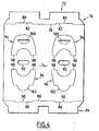
- Two oblong slots 92 are formed in the center of the central wall 74 one behind the other.
- a female tab 94 is cut in the central wall 74 to the left of each slot 92 and a male tab 96 is cut in the central wall 74 to the right of each slot 92.
- the female tabs 94 and the male tabs 96 have substantially U-shaped inverted shapes. They are connected to the remainder of the central wall 74 by longitudinal fold lines 98 arranged at the ends of the branches of the tabs 94 and 96.
- a notch 100 in the form of a disk sector is provided in each female lug 94.
- Each male lug 96 is extended by a tongue 102 in the form of a half-disk.
- the insert 12 is disposed inside the sheath 11 and the central wall 74 covers the lower pots 3 while the upper pots 3 rest on the central wall 74.
- the upper flanges 6 of the lower pots 3 are each engaged in an opening 104 thus ensuring longitudinal retention of the lower pots 3 with respect to the insert 12.
- the tabs 94 and 96 bordering each slot 92 are folded toward each other above the central wall 74 to form a trestle retaining member 106.
- the tongue 102 of the male lug 96 is then engaged in the notch 100 of the female lug 94 thus ensuring the holding of the retaining element 106.
- the two retaining elements 106 thus formed are arranged one behind the other above the central wall 74, the front element 106 being disposed between the upper front pots 3 and the rear element 106 between the upper pots 3 back.
- the retaining elements 106 retain the upper pots 3 both longitudinally and transversely with respect to the insert 12.
- the beams 64 are first formed on the lower wall 25 of the sheath 11, then the lower pots 3 are placed on the bottom wall 25.
- the spacer 12 is then placed on the lower pots 3 after having formed the retaining elements 106 on the central wall 74.
- the upper pots 3 are then placed on the insert 12 and then the side walls 16 and 27 of the sheath 11 are folded to envelop the group 2 of pots 3.
- top wall 15 is fixed to the fastening flap 32 by gluing.
- the slots 40 and 92 provided in the blanks 13 and 72 make it easy to handle them by means of suction cups and thus to automate the production of the assembly 1.
- the flaps 46 are each cut on the same side of a fold line 48 and folded over the lower wall 25 on the other side of this fold line 48, the bottom wall 25 may be of reduced dimensions.
- the cost of the blank 13 and the packaging 4 is therefore particularly small.
- the structure of the beams 64 formed by the flaps 46, and in particular their section, gives them a high rigidity so that the size of the openings 38 can be reduced.
- the risks of tearing of the sleeve 11 are reduced and a light weight cardboard or recycled cardboard can be used to form the sleeve 11, which further reduces the cost.
- the panels 56 on which the lower right pots 3 rest, also contribute to the strength of the beams 64.
- the insert 12 interposed between the lower pots 3 and the upper pots 3 protects the lids of the lower pots 3.
- openings 104 form lower pot retention means 3 which, in combination with the retaining elements 106 of the upper pots 3, allow satisfactory maintenance of the pots 3 in the sheath 11.
- the self-supporting structure of the retainers 106 also reduces the basis weight of the carton used to form the insert 12 so that the overall cost of the package 4 can be reduced.
- the two side walls 16 and 27 are not cut or deteriorated to ensure the retention of the lower pots 3 relative to the upper pots 3.
- holding beams 64 and the retaining means 104 and 106 may have different shapes from those described above.
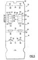
- Figure 5 shows a blank 13 to form a sheath 11 according to a second embodiment.
- This blank 13 differs from that of Figure 3 in that the side walls 16 and 27 are of smaller height and do not have a middle fold line. Thus, this blank 13 is intended to form a packaging package 4 of a group of pots 3 arranged in a single level. The package 4 therefore does not include tab 12.
- packaging pots 3 whose upper ends are interconnected, for example yogurt pots made by thermoforming a plastic plate.
- these principles can be used to package other types of containers than yoghurt pots.
Landscapes
- Engineering & Computer Science (AREA)
- Mechanical Engineering (AREA)
- Cartons (AREA)
- Packages (AREA)
Claims (12)
- Verpackung (4) zur Umhüllung einer Gruppe (2) von zumindest zwei Behältern (3), wobei die Verpackung in der Ausführung mit mindestens einer sich längs erstreckenden Schachtel (11) mit offenen Enden ausgebildet ist und Folgendes aufweist: eine obere Wand (15); eine untere Wand (25); zwei seitliche Wände (16, 27), welche die untere und die obere Wand verbinden; und ein Halte- bzw. Stützelement (64) der Behälter (3), wobei das Stützelement (64) von der unteren Wand (25) zur Anordnung zwischen Behältern (3) hervorragt, wobei das Stützelement (64) eine Klappe (46) aufweist, die aus der unteren Wand (25) ausgeschnitten und um eine Faltlinie (48) herum gefaltet ist, wobei die Klappe aus der unteren Wand (25) einer ersten Seite der Faltlinie (48) ausgeschnitten ist, dadurch gekennzeichnet, dass die Klappe (46) in Bezug auf die untere Wand (25) der der ersten Seite gegenüber liegenden Seite in Bezug auf die Faltlinie (48) gefaltet und befestigt ist.
- Verpackung nach Anspruch 1, dadurch gekennzeichnet, dass sich die Faltlinie (48) im Wesentlichen längs erstreckt, und dass das Stützelement (64) ein Querstützelement der Behälter (3) ist.
- Verpackung nach Anspruch 1 oder 2, dadurch gekennzeichnet, dass die Klappe (46) einen Endbereich (56) aufweist, durch welchen sie an der unteren Wand (25) befestigt ist.
- Verpackung nach Anspruch 3, dadurch gekennzeichnet, dass der Endbereich (56) der Klappe (46) durch eine Klebeverbindung an der unteren Wand (25) befestigt ist.
- Verpackung nach Anspruch 3 oder 4, dadurch gekennzeichnet, dass die Klappe (46) mehrere aufeinander folgende Bereiche bzw. Abschnitte (50, 52, 54, 56) aufweist, die miteinander durch Faltlinien (58) verbunden sind, wobei das Stützelement (64) einen vierseitigen Querschnitt aufweist.
- Verpackung nach einem der vorhergehenden Ansprüche, dadurch gekennzeichnet, dass, wobei die Gruppe (2) dazu vorgesehen ist, mindestens ein unteres Niveau bzw. einen unteren Bereich für Behälter (3) und ein oberes Niveau bzw. einen oberen Bereich für Behälter (3) aufzuweisen, die Verpackung weiterhin eine Zwischenlage (12) aufweist, welche zur Anordnung zwischen dem unteren Bereich und dem oberen Bereich für Behälter (3) vorgesehen ist.
- Verpackung nach Anspruch 6, dadurch gekennzeichnet, dass die Zwischenlage (12) erste Halteeinrichtungen (104) in Bezug auf die Behälter (3) des unteren Bereichs und zweite Halteeinrichtungen (106) des Behälter (3) des oberen Bereichs in Bezug auf die Zwischenlage (12) aufweist.
- Verpackung nach Anspruch 7, dadurch gekennzeichnet, dass die ersten Halteeinrichtungen Öffnungen (104) zur Aufnahme von oberen Abschnitten der Behälter (3) des unteren Bereiches aufweisen.
- Verpackung nach Anspruch 7 oder 8, dadurch gekennzeichnet, dass die zweiten Halteeinrichtungen (106) von der Zwischenlage (12) nach oben zur Anordnung zwischen den Behältern (3) des oberen Bereiches hervorragen.
- Verpackung nach Anspruch 9, dadurch gekennzeichnet, dass die zweiten Halteeinrichtungen mindestens zwei Lappen (94, 96) aufweisen, die aus der Zwischenlage (12) ausgeschnitten, gefaltet und miteinander in Eingriff sind.
- Anordnung, welche eine Gruppe (2) von mindestens zwei Behältern (3) und eine die Gruppe umhüllende Verpackung (4) aufweist, dadurch gekennzeichnet, dass die Verpackung eine Verpackung nach einem der vorhergehenden Ansprüche ist.
- Kartonzuschnitt, welcher vorher eingeschnitten und mit Knickrillen zur Bildung der Schachtel (11) einer Verpackung nach einem der Ansprüche 1 bis 10 versehen ist, wobei die Schachtel Folgendes aufweist: eine obere Wand (15), eine untere Wand (25); zwei seitliche Wände (16, 27), welche zur Verbindung der unteren und oberen Wand angepasst ist; eine Klappe (46), welche aus der unteren Wand (25) einer ersten Seite einer Faltlinie (48) ausgeschnitten ist, wobei die Klappe (46) um die Faltlinie (48) herum zur Befestigung in Bezug auf die untere Wand (25) der der ersten Seite in Bezug auf die Faltlinie gegenüber liegenden Seite und auf diese Weise zur Bildung eines Stützelementes von Behältern faltbar ist, wobei das Stützelement (64) dann von der unteren Wand (25) zur Anordnung zwischen Behältern (3) hervorragt.
Applications Claiming Priority (2)
| Application Number | Priority Date | Filing Date | Title |
|---|---|---|---|
| FR0216563 | 2002-12-23 | ||
| FR0216563A FR2848993B1 (fr) | 2002-12-23 | 2002-12-23 | Emballage comprenant un fourreau muni d'au moins un element de maintien de recipients, ensemble comprenant un tel emballage et des recipients et flan correspondants. |
Publications (2)
| Publication Number | Publication Date |
|---|---|
| EP1433713A1 EP1433713A1 (de) | 2004-06-30 |
| EP1433713B1 true EP1433713B1 (de) | 2006-03-15 |
Family
ID=32406437
Family Applications (1)
| Application Number | Title | Priority Date | Filing Date |
|---|---|---|---|
| EP03292877A Expired - Lifetime EP1433713B1 (de) | 2002-12-23 | 2003-11-18 | Verpackung mit einer Hülle mit mindestens einem Behälterbefestigungelement |
Country Status (6)
| Country | Link |
|---|---|
| EP (1) | EP1433713B1 (de) |
| AT (1) | ATE320389T1 (de) |
| DE (1) | DE60304020T2 (de) |
| ES (1) | ES2260591T3 (de) |
| FR (1) | FR2848993B1 (de) |
| PT (1) | PT1433713E (de) |
Cited By (2)
| Publication number | Priority date | Publication date | Assignee | Title |
|---|---|---|---|---|
| USD1066021S1 (en) | 2023-02-24 | 2025-03-11 | Cascades Canada Ulc | Packaging sleeve |
| USD1067783S1 (en) | 2023-02-24 | 2025-03-25 | Cascades Canada Ulc | Egg carton |
Family Cites Families (6)
| Publication number | Priority date | Publication date | Assignee | Title |
|---|---|---|---|---|
| US4703847A (en) * | 1987-01-30 | 1987-11-03 | The Mead Corporation | Multipack for flanged primary containers |
| GB2207904B (en) * | 1987-08-13 | 1991-01-30 | Bonar Cooke Cartons Ltd | Carton |
| DE3928076A1 (de) * | 1989-08-25 | 1991-02-28 | Unilever Nv | Verpackungstraeger |
| FR2723353B1 (fr) * | 1994-08-02 | 1996-10-31 | 4 P Emballages France | Suremballage pour un ensemble d'objets tels que des pots individuels a collerette, pourvu de moyens de calage perfectionnes |
| US5638956A (en) * | 1995-12-11 | 1997-06-17 | Riverwood International Corporation | Wrap-around carrier with lock-box keel |
| GB0010734D0 (en) * | 2000-05-04 | 2000-06-28 | Mead Corp | Carton and carton blank |
-
2002
- 2002-12-23 FR FR0216563A patent/FR2848993B1/fr not_active Expired - Fee Related
-
2003
- 2003-11-18 PT PT03292877T patent/PT1433713E/pt unknown
- 2003-11-18 EP EP03292877A patent/EP1433713B1/de not_active Expired - Lifetime
- 2003-11-18 ES ES03292877T patent/ES2260591T3/es not_active Expired - Lifetime
- 2003-11-18 DE DE60304020T patent/DE60304020T2/de not_active Expired - Fee Related
- 2003-11-18 AT AT03292877T patent/ATE320389T1/de not_active IP Right Cessation
Cited By (2)
| Publication number | Priority date | Publication date | Assignee | Title |
|---|---|---|---|---|
| USD1066021S1 (en) | 2023-02-24 | 2025-03-11 | Cascades Canada Ulc | Packaging sleeve |
| USD1067783S1 (en) | 2023-02-24 | 2025-03-25 | Cascades Canada Ulc | Egg carton |
Also Published As
| Publication number | Publication date |
|---|---|
| DE60304020D1 (de) | 2006-05-11 |
| DE60304020T2 (de) | 2006-11-02 |
| ES2260591T3 (es) | 2006-11-01 |
| ATE320389T1 (de) | 2006-04-15 |
| FR2848993A1 (fr) | 2004-06-25 |
| FR2848993B1 (fr) | 2005-07-08 |
| EP1433713A1 (de) | 2004-06-30 |
| PT1433713E (pt) | 2006-06-30 |
Similar Documents
| Publication | Publication Date | Title |
|---|---|---|
| EP0615920B1 (de) | Zuschnitt aus Karton zum Formen einer rohrförmigen Hülle zum Halten einer Behältergruppe und hieraus gefertigte Verpackung | |
| EP2225162B1 (de) | Verpackungsschachtel mit zentrierlasche und einem satz von aussparungen sowie verfahren zur herstellung einer solchen schachtel | |
| EP2635498B1 (de) | Schale mit erhöhten kanten und gerundeten zentriervorrichtungen sowie zuschnitt zur herstellung einer solchen schale | |
| EP0461947B1 (de) | Verpackungsvorrichtung für Gruppe von Objekten | |
| EP1433713B1 (de) | Verpackung mit einer Hülle mit mindestens einem Behälterbefestigungelement | |
| EP0972718B1 (de) | Umverpackung, Zuschnitt und eine die Waren umhüllende Verpackungseinheit | |
| EP0223623B1 (de) | Sich kreuzende Bänder, um in einem Behälter Abteilungen herzustellen | |
| FR2813588A1 (fr) | Emballage pour un groupe de recipients comprenant une bande transversale de maintien des recipients, flan correspondant et ensemble comprenant un tel emballage et des recipients | |
| FR3052444B1 (fr) | Emballage de type caisse americaine a fond automatique ou semi-automatique securise. | |
| FR2853886A1 (fr) | Boite en carton presentoir avec face avant ajouree | |
| FR2631314A1 (fr) | Recipient empilable perfectionne pour stockage et le transport | |
| FR2780703A1 (fr) | Contenant en un materiau semi-rigide pour le conditionnement d'objets divers et flan pour sa realisation | |
| EP1279618B1 (de) | Geschlossene Verpackungskiste und Deckel aus verschiedenen Materialien | |
| FR2813589A1 (fr) | Emballage pour un groupe de recipients comprenant une sangle transversale de retenue des recipients, flan correspondant et ensemble comprenant un tel emballage et des recipients | |
| FR2733740A1 (fr) | Emballage ferme pour le groupage d'un ensemble d'objets tels que des contenants de boissons | |
| WO1997030908A1 (fr) | Element de groupage pour l'assemblage d'emballages contenant des pots reunis en plaques | |
| FR2813587A1 (fr) | Emballage pour un groupe de recipients disposes en deux niveaux et comprenant des moyens de separation des recepients des deux niveaux, flan et ensemble comprenant des recipients correspondants | |
| EP0614821A1 (de) | Zuschnitt und Vorrichtung zum Halten und Greifen von Behälterlagen | |
| FR2832389A1 (fr) | Emballage pour objets lies par leurs extremites superieures, flan correspondant et ensemble comprenant un tel emballage et des objets | |
| FR2600307A1 (fr) | Emballage pour bouteilles couchees tete-beche | |
| EP1279617B1 (de) | Geschlossene Packung als steife Kiste und entprechender Zusammenbau aus zwei Zuschnitten | |
| EP2383191B1 (de) | Stackable cardboard tray and blank suitable for obtaining such a tray | |
| FR2719561A1 (fr) | Conditionnement, pour bouteilles ou autres récipients, en un matériau semi-rigide tel que le carton ondulé. | |
| FR2795390A1 (fr) | Caisse en carton et ensemble de decoupes pour obtenir une telle caisse | |
| FR2795049A1 (fr) | Caisse en carton et ensemble de decoupes pour obtenir une telle caisse |
Legal Events
| Date | Code | Title | Description |
|---|---|---|---|
| PUAI | Public reference made under article 153(3) epc to a published international application that has entered the european phase |
Free format text: ORIGINAL CODE: 0009012 |
|
| AK | Designated contracting states |
Kind code of ref document: A1 Designated state(s): AT BE BG CH CY CZ DE DK EE ES FI FR GB GR HU IE IT LI LU MC NL PT RO SE SI SK TR |
|
| AX | Request for extension of the european patent |
Extension state: AL LT LV MK |
|
| 17P | Request for examination filed |
Effective date: 20041210 |
|
| 17Q | First examination report despatched |
Effective date: 20050208 |
|
| AKX | Designation fees paid |
Designated state(s): AT BE BG CH CY CZ DE DK EE ES FI FR GB GR HU IE IT LI LU MC NL PT RO SE SI SK TR |
|
| GRAP | Despatch of communication of intention to grant a patent |
Free format text: ORIGINAL CODE: EPIDOSNIGR1 |
|
| GRAS | Grant fee paid |
Free format text: ORIGINAL CODE: EPIDOSNIGR3 |
|
| GRAA | (expected) grant |
Free format text: ORIGINAL CODE: 0009210 |
|
| AK | Designated contracting states |
Kind code of ref document: B1 Designated state(s): AT BE BG CH CY CZ DE DK EE ES FI FR GB GR HU IE IT LI LU MC NL PT RO SE SI SK TR |
|
| PG25 | Lapsed in a contracting state [announced via postgrant information from national office to epo] |
Ref country code: IT Free format text: LAPSE BECAUSE OF FAILURE TO SUBMIT A TRANSLATION OF THE DESCRIPTION OR TO PAY THE FEE WITHIN THE PRESCRIBED TIME-LIMIT;WARNING: LAPSES OF ITALIAN PATENTS WITH EFFECTIVE DATE BEFORE 2007 MAY HAVE OCCURRED AT ANY TIME BEFORE 2007. THE CORRECT EFFECTIVE DATE MAY BE DIFFERENT FROM THE ONE RECORDED. Effective date: 20060315 Ref country code: SK Free format text: LAPSE BECAUSE OF FAILURE TO SUBMIT A TRANSLATION OF THE DESCRIPTION OR TO PAY THE FEE WITHIN THE PRESCRIBED TIME-LIMIT Effective date: 20060315 Ref country code: SI Free format text: LAPSE BECAUSE OF FAILURE TO SUBMIT A TRANSLATION OF THE DESCRIPTION OR TO PAY THE FEE WITHIN THE PRESCRIBED TIME-LIMIT Effective date: 20060315 Ref country code: IE Free format text: LAPSE BECAUSE OF FAILURE TO SUBMIT A TRANSLATION OF THE DESCRIPTION OR TO PAY THE FEE WITHIN THE PRESCRIBED TIME-LIMIT Effective date: 20060315 Ref country code: FI Free format text: LAPSE BECAUSE OF FAILURE TO SUBMIT A TRANSLATION OF THE DESCRIPTION OR TO PAY THE FEE WITHIN THE PRESCRIBED TIME-LIMIT Effective date: 20060315 Ref country code: AT Free format text: LAPSE BECAUSE OF FAILURE TO SUBMIT A TRANSLATION OF THE DESCRIPTION OR TO PAY THE FEE WITHIN THE PRESCRIBED TIME-LIMIT Effective date: 20060315 Ref country code: RO Free format text: LAPSE BECAUSE OF FAILURE TO SUBMIT A TRANSLATION OF THE DESCRIPTION OR TO PAY THE FEE WITHIN THE PRESCRIBED TIME-LIMIT Effective date: 20060315 |
|
| REG | Reference to a national code |
Ref country code: GB Ref legal event code: FG4D Free format text: NOT ENGLISH Ref country code: CH Ref legal event code: EP |
|
| GBT | Gb: translation of ep patent filed (gb section 77(6)(a)/1977) |
Effective date: 20060315 |
|
| REG | Reference to a national code |
Ref country code: IE Ref legal event code: FG4D Free format text: LANGUAGE OF EP DOCUMENT: FRENCH |
|
| REF | Corresponds to: |
Ref document number: 60304020 Country of ref document: DE Date of ref document: 20060511 Kind code of ref document: P |
|
| PG25 | Lapsed in a contracting state [announced via postgrant information from national office to epo] |
Ref country code: SE Free format text: LAPSE BECAUSE OF FAILURE TO SUBMIT A TRANSLATION OF THE DESCRIPTION OR TO PAY THE FEE WITHIN THE PRESCRIBED TIME-LIMIT Effective date: 20060615 Ref country code: DK Free format text: LAPSE BECAUSE OF FAILURE TO SUBMIT A TRANSLATION OF THE DESCRIPTION OR TO PAY THE FEE WITHIN THE PRESCRIBED TIME-LIMIT Effective date: 20060615 Ref country code: BG Free format text: LAPSE BECAUSE OF FAILURE TO SUBMIT A TRANSLATION OF THE DESCRIPTION OR TO PAY THE FEE WITHIN THE PRESCRIBED TIME-LIMIT Effective date: 20060615 |
|
| REG | Reference to a national code |
Ref country code: PT Ref legal event code: SC4A Effective date: 20060421 |
|
| REG | Reference to a national code |
Ref country code: IE Ref legal event code: FD4D |
|
| REG | Reference to a national code |
Ref country code: ES Ref legal event code: FG2A Ref document number: 2260591 Country of ref document: ES Kind code of ref document: T3 |
|
| PG25 | Lapsed in a contracting state [announced via postgrant information from national office to epo] |
Ref country code: MC Free format text: LAPSE BECAUSE OF NON-PAYMENT OF DUE FEES Effective date: 20061130 |
|
| PLBE | No opposition filed within time limit |
Free format text: ORIGINAL CODE: 0009261 |
|
| STAA | Information on the status of an ep patent application or granted ep patent |
Free format text: STATUS: NO OPPOSITION FILED WITHIN TIME LIMIT |
|
| 26N | No opposition filed |
Effective date: 20061218 |
|
| REG | Reference to a national code |
Ref country code: FR Ref legal event code: TP |
|
| PGFP | Annual fee paid to national office [announced via postgrant information from national office to epo] |
Ref country code: DE Payment date: 20071108 Year of fee payment: 5 Ref country code: ES Payment date: 20071119 Year of fee payment: 5 Ref country code: NL Payment date: 20071017 Year of fee payment: 5 |
|
| PGFP | Annual fee paid to national office [announced via postgrant information from national office to epo] |
Ref country code: IT Payment date: 20071115 Year of fee payment: 5 |
|
| PGFP | Annual fee paid to national office [announced via postgrant information from national office to epo] |
Ref country code: BE Payment date: 20071203 Year of fee payment: 5 |
|
| PG25 | Lapsed in a contracting state [announced via postgrant information from national office to epo] |
Ref country code: GR Free format text: LAPSE BECAUSE OF FAILURE TO SUBMIT A TRANSLATION OF THE DESCRIPTION OR TO PAY THE FEE WITHIN THE PRESCRIBED TIME-LIMIT Effective date: 20060616 Ref country code: CZ Free format text: LAPSE BECAUSE OF FAILURE TO SUBMIT A TRANSLATION OF THE DESCRIPTION OR TO PAY THE FEE WITHIN THE PRESCRIBED TIME-LIMIT Effective date: 20060315 |
|
| PGFP | Annual fee paid to national office [announced via postgrant information from national office to epo] |
Ref country code: GB Payment date: 20071114 Year of fee payment: 5 |
|
| PGFP | Annual fee paid to national office [announced via postgrant information from national office to epo] |
Ref country code: PT Payment date: 20071017 Year of fee payment: 5 |
|
| PG25 | Lapsed in a contracting state [announced via postgrant information from national office to epo] |
Ref country code: EE Free format text: LAPSE BECAUSE OF FAILURE TO SUBMIT A TRANSLATION OF THE DESCRIPTION OR TO PAY THE FEE WITHIN THE PRESCRIBED TIME-LIMIT Effective date: 20060315 |
|
| PG25 | Lapsed in a contracting state [announced via postgrant information from national office to epo] |
Ref country code: HU Free format text: LAPSE BECAUSE OF FAILURE TO SUBMIT A TRANSLATION OF THE DESCRIPTION OR TO PAY THE FEE WITHIN THE PRESCRIBED TIME-LIMIT Effective date: 20060916 Ref country code: LI Free format text: LAPSE BECAUSE OF NON-PAYMENT OF DUE FEES Effective date: 20071130 Ref country code: TR Free format text: LAPSE BECAUSE OF FAILURE TO SUBMIT A TRANSLATION OF THE DESCRIPTION OR TO PAY THE FEE WITHIN THE PRESCRIBED TIME-LIMIT Effective date: 20060315 Ref country code: CH Free format text: LAPSE BECAUSE OF NON-PAYMENT OF DUE FEES Effective date: 20071130 Ref country code: LU Free format text: LAPSE BECAUSE OF NON-PAYMENT OF DUE FEES Effective date: 20061118 |
|
| REG | Reference to a national code |
Ref country code: CH Ref legal event code: PL |
|
| PG25 | Lapsed in a contracting state [announced via postgrant information from national office to epo] |
Ref country code: CY Free format text: LAPSE BECAUSE OF FAILURE TO SUBMIT A TRANSLATION OF THE DESCRIPTION OR TO PAY THE FEE WITHIN THE PRESCRIBED TIME-LIMIT Effective date: 20060315 |
|
| REG | Reference to a national code |
Ref country code: PT Ref legal event code: MM4A Free format text: LAPSE DUE TO NON-PAYMENT OF FEES Effective date: 20090518 |
|
| BERE | Be: lapsed |
Owner name: GOOSSENS BEAUVAIS Effective date: 20081130 |
|
| GBPC | Gb: european patent ceased through non-payment of renewal fee |
Effective date: 20081118 |
|
| PG25 | Lapsed in a contracting state [announced via postgrant information from national office to epo] |
Ref country code: NL Free format text: LAPSE BECAUSE OF NON-PAYMENT OF DUE FEES Effective date: 20090601 |
|
| NLV4 | Nl: lapsed or anulled due to non-payment of the annual fee |
Effective date: 20090601 |
|
| PG25 | Lapsed in a contracting state [announced via postgrant information from national office to epo] |
Ref country code: PT Free format text: LAPSE BECAUSE OF NON-PAYMENT OF DUE FEES Effective date: 20090518 Ref country code: IT Free format text: LAPSE BECAUSE OF NON-PAYMENT OF DUE FEES Effective date: 20081118 |
|
| PG25 | Lapsed in a contracting state [announced via postgrant information from national office to epo] |
Ref country code: BE Free format text: LAPSE BECAUSE OF NON-PAYMENT OF DUE FEES Effective date: 20081130 |
|
| PG25 | Lapsed in a contracting state [announced via postgrant information from national office to epo] |
Ref country code: DE Free format text: LAPSE BECAUSE OF NON-PAYMENT OF DUE FEES Effective date: 20090603 |
|
| PG25 | Lapsed in a contracting state [announced via postgrant information from national office to epo] |
Ref country code: GB Free format text: LAPSE BECAUSE OF NON-PAYMENT OF DUE FEES Effective date: 20081118 |
|
| REG | Reference to a national code |
Ref country code: ES Ref legal event code: FD2A Effective date: 20081119 |
|
| PG25 | Lapsed in a contracting state [announced via postgrant information from national office to epo] |
Ref country code: ES Free format text: LAPSE BECAUSE OF NON-PAYMENT OF DUE FEES Effective date: 20081119 |
|
| PGFP | Annual fee paid to national office [announced via postgrant information from national office to epo] |
Ref country code: FR Payment date: 20130419 Year of fee payment: 10 |
|
| REG | Reference to a national code |
Ref country code: FR Ref legal event code: ST Effective date: 20140731 |
|
| PG25 | Lapsed in a contracting state [announced via postgrant information from national office to epo] |
Ref country code: FR Free format text: LAPSE BECAUSE OF NON-PAYMENT OF DUE FEES Effective date: 20131202 |