EP1433577B1 - Werkzeug zum Durchtrennen von Rohren - Google Patents
Werkzeug zum Durchtrennen von Rohren Download PDFInfo
- Publication number
- EP1433577B1 EP1433577B1 EP02406148A EP02406148A EP1433577B1 EP 1433577 B1 EP1433577 B1 EP 1433577B1 EP 02406148 A EP02406148 A EP 02406148A EP 02406148 A EP02406148 A EP 02406148A EP 1433577 B1 EP1433577 B1 EP 1433577B1
- Authority
- EP
- European Patent Office
- Prior art keywords
- cutting
- tool
- cutting blade
- tool according
- pipe
- Prior art date
- Legal status (The legal status is an assumption and is not a legal conclusion. Google has not performed a legal analysis and makes no representation as to the accuracy of the status listed.)
- Expired - Lifetime
Links
Images
Classifications
-
- B—PERFORMING OPERATIONS; TRANSPORTING
- B23—MACHINE TOOLS; METAL-WORKING NOT OTHERWISE PROVIDED FOR
- B23D—PLANING; SLOTTING; SHEARING; BROACHING; SAWING; FILING; SCRAPING; LIKE OPERATIONS FOR WORKING METAL BY REMOVING MATERIAL, NOT OTHERWISE PROVIDED FOR
- B23D21/00—Machines or devices for shearing or cutting tubes
- B23D21/06—Hand-operated tube-cutters
- B23D21/10—Hand-operated tube-cutters with other cutting blades or tools
-
- B—PERFORMING OPERATIONS; TRANSPORTING
- B23—MACHINE TOOLS; METAL-WORKING NOT OTHERWISE PROVIDED FOR
- B23D—PLANING; SLOTTING; SHEARING; BROACHING; SAWING; FILING; SCRAPING; LIKE OPERATIONS FOR WORKING METAL BY REMOVING MATERIAL, NOT OTHERWISE PROVIDED FOR
- B23D21/00—Machines or devices for shearing or cutting tubes
- B23D21/06—Hand-operated tube-cutters
- B23D21/08—Hand-operated tube-cutters with cutting wheels
Definitions
- the invention relates to a tool for cutting pipes according to the preamble of claim 1.
- separating shears are often used, which are designed as a combination tool.
- a tool is for example from the EP 1 149 666 A2 have become known to the applicant.
- a cutting shear such a pipe is cut by hand in one movement.
- the combination tool therefore two laterally projecting mandrels are provided with which the pipe ends can be calibrated and chamfered.
- a cutting shear is also from the DE 196 49 992 A become. Also in this a free-cutting knife blade is provided, the cutting edge is guided straight ahead.
- pipe cutters For cutting through pipes, so-called pipe cutters are known with which pipes with a diameter of, for example, up to 26 mm can be cut through. Such pipe cutters each have an undeliverable cutting roller. The tool is turned around the pipe and with each handling the cutting roller is delivered accordingly. Tubes can thus be cut through substantially without deformation. However, the pipe cutter must be turned several times around the pipe and the cutting roller must be delivered. The operation takes much longer than in the above-mentioned cutting shear.
- Such a pipe cutter shows the US-A-5,206,996 , This has a roller blade which is pressed by the pressure of a spring to the cutting pipe.
- the invention has for its object to provide the pipe fitter in the plumbing and heating a tool available, can be easily and quickly cut through the pipes with a much larger dimension range.
- the tubes are thus severed in two processing steps.
- a first step the tube is at least partially cut on the circumference and pushed through in a second processing step.
- the cutting of the tube at its periphery is made possible by the movable mounting of the cutting blade on a pliers limb.
- the knife can be cut on the circumference of the pipe without pulling.
- the cutting blade penetrates into the tube one.
- the already partially cut tube can then be pushed through, with the tool now serving as a cutting shear.
- Tubes with a comparatively small outside diameter can also be pushed through with the tool in a single machining operation. For pipes with a larger diameter, however, the cutting is done in the above-mentioned two processing steps.
- the inventive tool results in a higher cutting effect with less deformation of the tubes and is still compact and handy.
- the cutting of the tube in the first processing step can be carried out particularly effectively if, according to a development of the invention, the cutting blade has an arcuate cutting region.
- the cutting blade can roll on the circumference of the tube during the cutting process and penetrate with the cutting edge in the pipe.
- the cutting blade annular, so a particularly compact and handy design is possible. Nevertheless, pipes with a large outer diameter can be cut through. Alternatively, this is also possible if according to a development of the invention, the cutting blade is formed part-circular and pivotally mounted. The cutting blade forms a rocker.
- the pipe bearing is designed as a roller bearing.
- the tool can be rotated in this case with little friction and thus with a smaller torque around the pipe.
- tool 1 is a tool to be operated by hand and has two pliers legs 2 and 3, which are pivotable about a common hinge axis 8 against each other. To close the pliers legs 2 and 3, these each have a handle 5 and 7 respectively. These handles 5 and 7 are only partially shown.
- a pivotable latch 19 is arranged on the handle 5 .
- a cup-shaped pipe guide 20 is fixed, in which a pipe to be machined 14 can be inserted.
- the pipe guide 20 is fastened with two screws 22 on the pliers arm 3 and can be replaced.
- a tube 14 is rotatably mounted, which has a comparatively large outer diameter, for example, more than 20 mm.
- Tubes 14 'with a mean outer diameter and smaller tubes 14 "are outside the areas of the guide rollers 15 and 16.
- the outer diameter of the smaller tube 14" is 16 mm, for example, and the tubes 14, 14' and 14 "are especially water pipes for sanitary engineering.
- the tool has 1 processing parts 17 and 18 which are interchangeable with clamping screws 21 attached to the pliers legs 2 and 3 and which form a second effective range.
- the tool 1 is a combination tool.
- the processing parts 17 and 18 are not mandatory and may also be omitted or replaced by other processing parts.
- the pliers leg 2 has a knife guard 11, according to FIG. 5 is attached with two screws 23. Between the plate-shaped forceps arms 2, an annular knife 9 is rotatably mounted on a guide rail 12. This annular knife 9 has on the outside and at least partially a cutting area 10 which is formed as a cutting edge. How the particular FIG. 2 shows the knife 9, the rear side 24 of the forceps leg 2. This has the advantage that the pivot point D of the knife 9 is positioned comparatively far out and the knife 9 occupies only a portion of the forceps jaw portion A. Thus, pipes 14 can be processed with a comparatively large outer diameter, without the tool 1 must be made very large.
- FIG. 1 To cut through a pipe 14, 14 'or 14 ", this is according to FIG. 1 inserted in the guide 20.
- the forceps jaw area A is according to FIG. 1 opened accordingly.
- the knife 9 is applied with the cutting area 10 to the circumference of the tube 14, 14 'and 14''by corresponding closure of the tool 1.
- the tool 1 While maintaining the contact pressure, the tool 1 is now rotated about the longitudinal axis of the tube 14, 14 'and 14 ", the knife 9 in the tube 14, 14' and 14" cuts, wherein the movable blade 9 mounted on the circumference of the Tube 14, 14 'and 14 ", respectively.
- the knife 9 thus rotates in the guide disc which is held by an axle 13-.
- the tool 1 is here, for example, rotated only by 90 °.
- the knife 9 cuts deeper and deeper into the tube 14, 14 'or 14 ", respectively, when a certain depth of incision has been reached, the tool 1 is used as a pair of pliers and the tube 14, 14 'and 14 "completely pushed by closing the tool 1.
- the FIG. 4 shows the tool 1 in the closed state.
- the tube 14, 14 'or 14 " is in this case completely severed.
- the tool 1 can be opened again and attached to another tube.
- FIGS. 6 to 9 show a tool according to the invention 30, which is used the same as the tool 1 and a pliers leg 2 'and a pliers leg 3' has.
- the forceps guide 20, which is mentioned above, is fastened to the forceps limb 3 ', into which the tube 14, 14' or 14 "to be severed is inserted, and a cutting blade 31 is mounted on the forceps limb 2 ', which is mounted pivotably about an axis 33 between two plates 36
- the blade 31 has an arcuate cutting edge 32 which extends between two substantially radially extending edges 37. As can be seen, the angle ⁇ between these two edges 37 is somewhat greater than 90 ° , according to FIG. 6 starting from the basic position, which is held by two leaf springs 38, according to double arrow 34 can be pivoted by 45 ° and according to the double arrow 35 by 44 °.
- the knife 31 thus forms a rocker.
- the knife 31 is applied to this for severing the tube 14, 14 'and 14 ",.
- the tool 30 is reciprocated about the longitudinal axis of the tube 14, 14' or 14".
- the angle of rotation is here in the range below 44 or 45 °.
- the knife cuts into the pipe 14, 14 'and 14 "with the cutting edge 32.
- the tool 30 is used as a pair of pliers and the pipe 14, 14' or 14" is completely pushed through.
- the knife 31 completely cuts through the tube 14, 14 'or 14''.
- the FIG. 8 shows the tool 30 in the closed position.
- the tube 14, 14 'or 14 " is thus completely and smoothly severed, and the tool 30 can now be opened again and applied to another tube.
- the axis of rotation 33 of the blade 31 is offset comparatively far outward. For a circular knife, this would hardly be possible or impractical, since this would project on the back of the forceps leg 2 '.
Landscapes
- Engineering & Computer Science (AREA)
- Mechanical Engineering (AREA)
- Scissors And Nippers (AREA)
- Cutting Tools, Boring Holders, And Turrets (AREA)
- Knives (AREA)
- Pressure Welding/Diffusion-Bonding (AREA)
Description
- Die Erfindung betrifft ein Werkzeug zum Durchtrennen von Rohren gemäss Oberbegriff des Anspruchs 1.
- Für Rohre mit kleinerem Aussendurchmesser werden häufig Trennscheren verwendet, die als Kombinationswerkzeug ausgebildet sind. Ein solches Werkzeuge ist beispielsweise aus der
EP 1 149 666 A2 des Anmelders bekannt geworden. Mit einer solchen Trennschere wird ein Rohr von Hand in einer Bewegung durchschnitten. Beim Trennvorgang werden die entstehenden beiden Rohrende in der Regel etwas deformiert. Am Kombinationswerkzeug sind deshalb zwei seitlich vorstehende Dorne vorgesehen, mit denen die Rohrenden kalibriert und angefast werden können. Eine Trennschere ist auch aus derDE 196 49 992 A geworden. Auch bei diesem ist eine frei schneidende Messerklinge vorgesehen, dessen Schneide geradeaus geführt ist. Für Rohre mit grösserem Aussendurchmesser und/oder dickerer Schutzbeschichtung wird vorgeschlagen, die Schneide der Messerklinge schräg zum Zangenschliesswinkel auszuführen, um einen mehr ziehenden Schnitt zu erreichen. Aber auch damit lassen sich Rohre mit einem Durchmesser über etwa 20 mm nur mühsam durchtrennen. Zudem kann hier nicht vermieden werden, dass die Rohre stark gequetscht und damit anschliessend wieder bearbeitet werden müssen. - Zum Durchtrennen von Rohren sind auch sogenannte Rohrabschneider bekannt, mit denen Rohre mit einem Durchmesser von beispielsweise bis 26 mm durchtrennt werden können. Solche Rohrabschneider weisen jeweils eine zustellbare Schneidrolle auf. Das Werkzeug wird um das Rohr herumgedreht und bei jedem Umgang wird die Schneidrolle entsprechend zugestellt. Rohre können damit im Wesentlichen ohne Deformation durchgetrennt werden. Der Rohrschneider muss aber jeweils mehrmals um das Rohr herumgedreht und die Schneidrolle zugestellt werden. Der Arbeitsvorgang dauert wesentlich länger als bei der oben genannten Trennschere.
- Einen solchen Rohrabschneider zeigt die
US-A-5,206,996 . Dieser besitzt ein Rollenmesser, das durch den Druck einer Feder an das schneidende Rohr angepresst wird. - Der Erfindung liegt die Aufgabe zugrunde, dem Rohrmonteur in der Sanitärtechnik und im Heizungsbereich ein Werkzeug zur Verfügung zu stellen, mit dem Leitungsrohre mit einem wesentlich grösseren Dimensionsbereich einfach und schnell durchtrennt werden können.
- Die Aufgabe ist durch die Merkmalkombination von Anspruch 1 gelöst. . Mit dem erfindungsgemässen Werkzeug werden die Rohre somit in zwei Bearbeitungsschritten durchtrennt. In einem ersten Schritt wird das Rohr am Umfang wenigstens teilweise geschnitten und in einem zweiten Bearbeitungsschritt durchgedrückt. Das Schneiden des Rohres an seinem Umfang wird durch die bewegliche Lagerung des Schneidmessers an einem Zangenschenkel ermöglicht. Beim Schneidvorgang kann das Messer am Umfang des Rohres ohne Ziehen geschnitten werden. Das Schneidmesser dringt hierbei in das Rohr ein. Das bereits teilweise geschnittene Rohr kann dann durchgedrückt werden, wobei das Werkzeug hier nun als Trennschere dient. Rohre mit einem vergleichsweise kleinen Aussendurchmesser können mit dem Werkzeug auch in einem einzigen Bearbeitungsgang durchgedrückt werden. Bei Rohren mit einem grösseren Durchmesser, erfolgt das Durchtrennen jedoch in den genannten beiden Bearbeitungsschritten. Das erfindungsgemässe Werkzeug ergibt eine höhere Schneidwirkung bei geringerer Deformation der Rohre und ist trotzdem kompakt und handlich.
- Das Schneiden des Rohres im ersten Bearbeitungsschritt kann dann besonders wirksam durchgeführt werden, wenn gemäss einer Weiterbildung der Erfindung das Schneidmesser einen bogenförmigen Schneidbereich aufweist. Das Schneidmesser kann am Umfang des Rohres beim Schneidvorgang abrollen und mit der Schneidkante in das Rohr eindringen.
- Ist nach einer Weiterbildung der Erfindung das Schneidmesser ringförmig ausgebildet, so ist eine besonders kompakte und handliche Ausführung möglich. Trotzdem können Rohre mit grossem Aussendurchmesser durchgetrennt werden. Alternativ ist dies auch möglich, wenn gemäss einer Weiterbildung der Erfindung das Schneidmesser teilkreisförmig ausgebildet und schwenkbar gelagert ist. Das Schneidmesser bildet hierbei eine Wippe.
- Eine besonders einfache Bearbeitung ergibt sich dann, wenn gemäss einer Weiterbildung der Erfindung das Rohrlager als Rollenlager ausgebildet ist. Das Werkzeug kann in diesem Fall mit wenig Reibung und damit mit einem kleineren Drehmoment um das Rohr gedreht werden.
- Weitere vorteilhafte Merkmale ergeben sich aus den abhängigen Patentansprüche, der nachfolgenden Beschreibung sowie der Zeichnung.
- Ein Ausführungsbeispiel der Erfindung wird nachfolgend anhand der Zeichnung näher erläutert. Es zeigen:
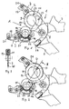
- Figur 1
- eine Ansicht eines erfindungsgemässen Werkzeugs,
- Figur 2
- eine weitere Ansicht des Werkzeugs gemäss
Figur 1 , wobei zur besseren Sichtbarkeit des Schneidmessers Teile weggelassen sind, - Figur 3
- ein Schnitt entlang der Linie III-III der
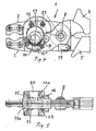
Figur 2 , - Figur 4
- eine Ansicht des Werkzeugs gemäss
Figur 1 , jedoch nach dem Durchtrennen eines Rohres, - Figur 5
- eine weitere Ansicht des Werkzeugs gemäss
Figur 4 , - Figur 6
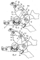
- eine Ansicht eines erfindungsgemässen Werkzeugs gemäss einer Variante,
- Figur 7
- eine Ansicht des Werkzeugs gemäss
Figur 6 , wobei zur besseren Sichtbarkeit des Schneidmessers Teile weggelassen sind, - Figur 8
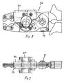
- eine Ansicht des Werkzeugs gemäss
Figur 6 , jedoch im geschlossenen Zustand nach dem Durchtrennen eines Rohres und - Figur 9
- eine weitere Ansicht des Werkzeugs gemäss
Figur 8 . - Das in
Figur 1 gezeigte Werkzeug 1 ist ein von Hand zu betätigendes Werkzeug und weist zwei Zangenschenkel 2 und 3 auf, die um eine gemeinsame Gelenkachse 8 gegeneinander verschwenkbar sind. Zum Schliessen der Zangenschenkel 2 und 3 weisen diese jeweils einen Griff 5 bzw. 7 auf. Diese Griffe 5 und 7 sind lediglich teilweise dargestellt. Zur Feststellung des Werkzeugs 1 in der geschlossenen Position gemäss derFigur 4 ist am Griff 5 ein schwenkbarer Riegel 19 angeordnet. - Am Zangenschenkel 3 ist eine schalenförmige Rohrführung 20 befestigt, in die ein zu bearbeitendes Rohr 14 eingelegt werden kann. Die Rohrführung 20 ist mit zwei Schrauben 22 am Zangenschenkel 3 befestigt und kann ausgewechselt werden. In der Führung 20 sind im Abstand zueinander zwei Führungsrollen 15 und 16 angeordnet, an denen gemäss den
Figuren 1 und 2 ein Rohr 14 drehbar gelagert ist, das einen vergleichsweise grossen Aussendurchmesser, von beispielsweise mehr als 20 mm aufweist. Rohre 14' mit mittlerem Aussendurchmesser und kleinere Rohre 14'' liegen ausserhalb der Bereiche der Führungsrollen 15 und 16. Der Aussendurchmesser des kleineren Rohres 14" beträgt beispielsweise 16 mm. Die Rohre 14, 14' und 14'' sind insbesondere Wasserrohre der Sanitärtechnik, die in an sich bekannter Weise und hier nicht dargestellt eine mittlere Schicht aus Aluminium, eine innere Schicht aus einem Kunststoff sowie eine äussere Schicht ebenfalls aus Kunststoff aufweisen. Solche Rohre sind biegbar und zur Herstellung einer Pressverbindung plastisch verformbar. Solche Rohre 14 sind vielfach von einem hier nicht gezeigten Wellrohr aus Kunststoff umgeben. Um solche Wellrohre durchzuschneiden, weist das Werkzeug 1 Bearbeitungsteile 17 und 18 auf, die mit Klemmschrauben 21 auswechselbar an den Zangenschenkeln 2 und 3 befestigt sind und die einen zweiten Wirkbereich bilden. Das Werkzeug 1 ist ein Kombinationswerkzeug. Die Bearbeitungsteile 17 und 18 sind jedoch nicht zwingend und können auch weggelassen oder durch andere Bearbeitungsteile ersetzt sein. - Der Zangenschenkel 2 weist einen Messerschutz 11 auf, der gemäss
Figur 5 mit zwei Schrauben 23 befestigt ist. Zwischen den plattenförmigen Zangenschenkeln 2 ist ein ringförmiges Messer 9 drehbar auf einer Führungsschiene 12 gelagert. Dieses ringförmige Messer 9 weist aussenseitig und wenigstens bereichsweise einen Schneidbereich 10 auf, der als Schneidkante ausgebildet ist. Wie insbesondere dieFigur 2 zeigt, überragt das Messer 9 die Rückseite 24 des Zangenschenkels 2. Dies hat den Vorteil, dass der Drehpunkt D des Messers 9 vergleichsweise weit aussen positioniert ist und das Messer 9 lediglich einen Teilbereich des Zangenmaulbereichs A einnimmt. Damit können auch Rohre 14 mit einem vergleichsweise grossen Aussendurchmesser bearbeitet werden, ohne dass das Werkzeug 1 sehr gross ausgebildet sein muss. - Um ein Rohr 14, 14' oder 14" durchzutrennen, wird dieses gemäss
Figur 1 in die Führung 20 eingelegt. Hierbei ist der Zangenmaulbereich A gemässFigur 1 entsprechend geöffnet. Das Messer 9 wird mit dem Schneidbereich 10 an den Umfang des Rohres 14, 14' bzw. 14'' durch entsprechendes Schliessen des Werkzeuges 1 angelegt. Unter Beibehaltung des Anpressdruckes wird nun das Werkzeug 1 um die Längsachse des Rohres 14, 14' bzw. 14" gedreht, wobei das Messer 9 in das Rohr 14, 14' bzw. 14" einschneidet, wobei das beweglich gelagerte Messer 9 am Umfang des Rohres 14, 14' bzw. 14" abrollt. Das Messer 9 dreht somit in der Führungsscheibe die von einer Achse 13 gehalten ist-. Das Werkzeug 1 wird hierbei beispielsweise lediglich um 90° gedreht. Durch Zurückdrehen und wieder nach vorne Drehen schneidet das Messer 9 immer tiefer in das Rohr 14, 14' bzw. 14" ein. Ist eine gewisse Tiefe des Einschnittes erreicht, so wird das Werkzeug 1 als Zange bzw. Schere verwendet und das Rohr 14, 14' bzw. 14" durch Schliessen des Werkzeugs 1 vollständig durchgedrückt. DieFigur 4 zeigt das Werkzeug 1 in geschlossenem Zustand. Das Rohr 14, 14' bzw. 14" ist hierbei vollständig durchtrennt. Das Werkzeug 1 kann wieder geöffnet und an ein weiteres Rohr angesetzt werden. - Die
Figuren 6 bis 9 zeigen ein erfindungsgemässes Werkzeug 30, das gleich verwendet wird wie das Werkzeug 1 und einen Zangenschenkel 2' sowie einen Zangenschenkel 3' aufweist. Am Zangenschenkel 3' ist die oben erwähnte Zangenführung 20 befestigt, in welche das zu durchtrennende Rohr 14, 14' bzw. 14" einzulegen ist. Am Zangenschenkel 2' ist ein Schneidmesser 31 gelagert, das zwischen zwei Platten 36 schwenkbar um eine Achse 33 gelagert ist. Das Messer 31 besitzt eine bogenförmige Schneidkante 32, die sich zwischen zwei im Wesentlichen radial verlaufenden Kanten 37 erstreckt. Der Winkel α zwischen diesen beiden Kanten 37 ist wie ersichtlich etwas grösser als 90°. Das Messer 31 ist um die Achse 33 begrenzt verschwenkbar, wobei gemässFigur 6 ausgehend von der Grundstellung, die durch zwei Blattfedern 38 gehalten wird, gemäss Doppelpfeil 34 um 45° und gemäss Doppelpfeil 35 um 44° verschwenkbar ist. Das Messer 31 bildet damit eine Wippe. - Wie die
Figur 7 zeigt, wird das Messer 31 zum Durchtrennen des Rohres 14, 14' bzw. 14" an dieses angelegt. Unter bleibendem Schliessdruck wird das Werkzeug 30 um die Längsachse des Rohres 14, 14' bzw. 14" hin- und herbewegt. Der Drehwinkel liegt hier im Bereich unterhalb von 44 bzw. 45°. Das Messer schneidet mit der Schneidkante 32 in das Rohr 14, 14' und 14" ein. Nach diesen Wippbewegungen wird das Werkzeug 30 als Schere bzw. Zange verwendet und das Rohr 14, 14' bzw. 14" vollständig durchgedrückt. Das Messer 31 durchtrennt hierbei vollständig das Rohr 14, 14' bzw. 14''. DieFigur 8 zeigt das Werkzeug 30 in der geschlossenen Stellung. Das Rohr 14, 14' bzw. 14" ist damit vollständig und glatt durchgetrennt. Das Werkzeug 30 kann nun wieder geöffnet und an ein weiteres Rohr angelegt werden. - Wie insbesondere die
Figur 7 zeigt, ist die Drehachse 33 des Messers 31 vergleichsweise weit nach aussen versetzt. Bei einem kreisförmigen Messer wäre dies kaum möglich oder unpraktisch, da dieses auf der Rückseite des Zangenschenkels 2' vorragen würde. Durch die Ausbildung des Messers 31 als Wippe bzw. als Segment ist dies vermieden. Mit einer vergleichsweise kleinen Zange können damit Rohre mit einem Aussendurchmesser von beispielsweise 26 mm durchgetrennt werden.
Claims (10)
- Werkzeug zum Durchtrennen von Rohren, insbesondere Wasserrohre der Sanitär- und Heizungstechnik, mit zwei Zangenschenkeln (2, 2'; 3, 3'), die um eine Gelenkachse (8) zueinander verschwenkbar sind, mit wenigstens einem in einem zangenmaulbereich (A) angeordneten Schneidmesser (9, 31) und einer Rohrführung (20) im Zangenmaulbereich (A), wobei das Schneidmesser (9, 31) beweglich an einem der Zangenschenkel (2, 2'; 3, 3') gelagert ist und mit diesem Schneidmesser (9, 31) das Rohr (14, 14', 14") in einem ersten Bearbeitungsschritt wenigstens teilweise am Umfang schneidbar ist, dadurch gekennzeichnet, dass die zwei Zangenschenkel (2, 2'; 3, 3') eine Trennschere bilden, dass das Schneidmesser (9) so ausgebildet ist, dass das Rohr (14, 14', 14") in einem zweiten Bearbeitungsschritt durchdrückbar ist, wobei das Werkzeug in diesem zweiten Bearbeitungsschritt als Trennschere dient und die Zangenschenkel (2, 2'; 3, 3') hierzu an Griffen (5, 7) zusammendrückbar sind.
- Werkzeug nach Anspruch 1, dadurch gekennzeichnet, dass das Schneidmesser (9, 31) einen bogenförmigen Schneidbereich (10, 32) aufweist.
- Werkzeug nach Anspruch 1, dadurch gekennzeichnet, dass das Schneidmesser (9) als Rad ausgebildet ist.
- Werkzeug nach einem der Ansprüche 1 bis 3, dadurch gekennzeichnet, dass das Schneidmesser (9) ringförmig ausgebildet ist.
- Werkzeug nach einem der Ansprüche 1 bis 3, dadurch gekennzeichnet, dass das Schneidmesser (9) an seinem Umfang drehbar gelagert ist.
- Werkzeug nach Anspruch 5, dadurch gekennzeichnet, dass das Schneidmesser (9) zwischen zwei plattenförmigen Führungsteilen (36) gelagert ist.
- Werkzeug nach Anspruch 1, dadurch gekennzeichnet, dass das Schneidmesser (31) schwenkbar an einer Schwenkachse (33) gelagert ist.
- Werkzeug nach Anspruch 7, dadurch gekennzeichnet, dass das Schneidmesser (31) als wippe ausgebildet ist und einen teilkreisförmigen Schneidbereicht (32) aufweist.
- Werkzeug nach Anspruch 8, dadurch gekennzeichnet, dass das Werkzeug (31) zwei im Wesentlichen radial verlaufende Kanten (37) aufweist, zwischen denen der Schneidbereich (32) verläuft.
- Werkzeug nach einem der Ansprüche 1 bis 9, dadurch gekennzeichnet, dass die Rohrführung (20) ein Rollenlager (22) aufweist.
Priority Applications (3)
| Application Number | Priority Date | Filing Date | Title |
|---|---|---|---|
| AT02406148T ATE442943T1 (de) | 2002-12-27 | 2002-12-27 | Werkzeug zum durchtrennen von rohren |
| EP02406148A EP1433577B1 (de) | 2002-12-27 | 2002-12-27 | Werkzeug zum Durchtrennen von Rohren |
| DE50213855T DE50213855D1 (de) | 2002-12-27 | 2002-12-27 | Werkzeug zum Durchtrennen von Rohren |
Applications Claiming Priority (1)
| Application Number | Priority Date | Filing Date | Title |
|---|---|---|---|
| EP02406148A EP1433577B1 (de) | 2002-12-27 | 2002-12-27 | Werkzeug zum Durchtrennen von Rohren |
Publications (2)
| Publication Number | Publication Date |
|---|---|
| EP1433577A1 EP1433577A1 (de) | 2004-06-30 |
| EP1433577B1 true EP1433577B1 (de) | 2009-09-16 |
Family
ID=32405834
Family Applications (1)
| Application Number | Title | Priority Date | Filing Date |
|---|---|---|---|
| EP02406148A Expired - Lifetime EP1433577B1 (de) | 2002-12-27 | 2002-12-27 | Werkzeug zum Durchtrennen von Rohren |
Country Status (3)
| Country | Link |
|---|---|
| EP (1) | EP1433577B1 (de) |
| AT (1) | ATE442943T1 (de) |
| DE (1) | DE50213855D1 (de) |
Families Citing this family (2)
| Publication number | Priority date | Publication date | Assignee | Title |
|---|---|---|---|---|
| ES2614132B1 (es) * | 2015-10-27 | 2018-03-12 | Zenten Bernhard Groten, S.L. | Tijera para el corte de tubos |
| US9908185B1 (en) * | 2016-11-21 | 2018-03-06 | Jiin Haur Industrial Co., Ltd. | Cutting device with wheeled blades |
Family Cites Families (6)
| Publication number | Priority date | Publication date | Assignee | Title |
|---|---|---|---|---|
| DE9010931U1 (de) * | 1990-07-24 | 1991-11-21 | Knipex-Werk C. Gustav Putsch, 5600 Wuppertal | Ratschenschneider |
| US5206996A (en) * | 1992-04-01 | 1993-05-04 | Mcdaniel William A | Tubing cutters |
| DE19649992C2 (de) * | 1996-11-21 | 1999-03-04 | Rennsteig Werkzeuge Gmbh | Zangenartiges Werkzeug |
| DE20003693U1 (de) * | 2000-02-29 | 2000-05-18 | Klamert, Dieter, 87700 Memmingen | Rohrabschneider für Sanitär- und Heizungsinstallation mit 4 Schneidrädern |
| DE20104034U1 (de) * | 2000-04-28 | 2001-05-10 | Geberit Technik Ag, Jona | Zangenartiges Kombinationswerkzeug |
| US6305087B1 (en) * | 2000-07-27 | 2001-10-23 | Hong Chuan Hsian Industries Co., Ltd. | Shears for cutting water pipe and the like |
-
2002
- 2002-12-27 AT AT02406148T patent/ATE442943T1/de active
- 2002-12-27 DE DE50213855T patent/DE50213855D1/de not_active Expired - Lifetime
- 2002-12-27 EP EP02406148A patent/EP1433577B1/de not_active Expired - Lifetime
Also Published As
| Publication number | Publication date |
|---|---|
| EP1433577A1 (de) | 2004-06-30 |
| ATE442943T1 (de) | 2009-10-15 |
| DE50213855D1 (de) | 2009-10-29 |
Similar Documents
| Publication | Publication Date | Title |
|---|---|---|
| EP2709804B1 (de) | Zange | |
| WO1998040178A1 (de) | Presswerkzeug | |
| EP0454615B1 (de) | Zange zum Schneiden chirurgischer Nägel, Drähte od.dgl. | |
| EP4104263B1 (de) | Zangenartiges schneidwerkzeug | |
| WO2020228903A1 (de) | Rohrschneider zum schneiden eines rundrohres und verfahren zum ablängen eines rundrohres | |
| EP1459825B1 (de) | Trennvorrichtung für Werkstücke, wie Stangen, Bolzen und dergleichen, insbesondere für Gewindestangen | |
| EP0543216B1 (de) | Vorrichtung zum Abschneiden von Rohren | |
| EP1356326B1 (de) | Zangenartiges werkzeug und verfahren zum durchtrennen von lichtwellenleiterkabeln | |
| EP3600776B1 (de) | Pressmatrize für ein presswerkzeug zum verpressen von rundrohrförmigen werkstückabschnitten | |
| EP1295688B1 (de) | Vorrichtung sowie Verfahren zum Trennen von Rohren | |
| EP2915618B1 (de) | Zange oder schere | |
| EP0247553B1 (de) | Vorrichtung zum spanlosen Zertrennen von Rohren | |
| DE20221492U1 (de) | Werkzeug zum Durchtrennen von Rohren | |
| DE19649992C2 (de) | Zangenartiges Werkzeug | |
| EP0763398B1 (de) | Verfahren und Vorrichtung zur Beseitigung eines Stauchgrates | |
| DE10053863C1 (de) | Verfahren und Vorrichtung zur Trennung eines Rohres | |
| EP1433577A1 (de) | Werkzeug zum Durchtrennen von Rohren | |
| EP2500140B1 (de) | Vorrichtung zum Bearbeiten von Rundkörpern | |
| DE112007001295B4 (de) | Verfahren und Vorrichtung zum Biegen eines Klingenmaterials | |
| DE102015106623A1 (de) | Werkzeug zum Schneiden und Verschließen eines Schlauches | |
| DE10024083C1 (de) | Schere zum Durchtrennen eines Verbundrohres | |
| DE3704989A1 (de) | Verfahren und einrichtung zur herstellung von teilkreisfoermigen bogenelementen | |
| DE29824956U1 (de) | Presswerkzeug | |
| EP0058349A2 (de) | Werkzeug zum Verformen, Drücken oder zur Durchführung anderer Arbeitsgänge unter Anwendung von Druck | |
| DE10056780A1 (de) | Schneidvorrichtung zum Trennen von Lichtwellenleitern |
Legal Events
| Date | Code | Title | Description |
|---|---|---|---|
| PUAI | Public reference made under article 153(3) epc to a published international application that has entered the european phase |
Free format text: ORIGINAL CODE: 0009012 |
|
| AK | Designated contracting states |
Kind code of ref document: A1 Designated state(s): AT BE BG CH CY CZ DE DK EE ES FI FR GB GR IE IT LI LU MC NL PT SE SI SK TR |
|
| AX | Request for extension of the european patent |
Extension state: AL LT LV MK RO |
|
| 17P | Request for examination filed |
Effective date: 20040814 |
|
| 17Q | First examination report despatched |
Effective date: 20041220 |
|
| AKX | Designation fees paid |
Designated state(s): AT BE BG CH CY CZ DE DK EE ES FI FR GB GR IE IT LI LU MC NL PT SE SI SK TR |
|
| APBN | Date of receipt of notice of appeal recorded |
Free format text: ORIGINAL CODE: EPIDOSNNOA2E |
|
| APBR | Date of receipt of statement of grounds of appeal recorded |
Free format text: ORIGINAL CODE: EPIDOSNNOA3E |
|
| APAF | Appeal reference modified |
Free format text: ORIGINAL CODE: EPIDOSCREFNE |
|
| APBT | Appeal procedure closed |
Free format text: ORIGINAL CODE: EPIDOSNNOA9E |
|
| GRAP | Despatch of communication of intention to grant a patent |
Free format text: ORIGINAL CODE: EPIDOSNIGR1 |
|
| GRAS | Grant fee paid |
Free format text: ORIGINAL CODE: EPIDOSNIGR3 |
|
| GRAA | (expected) grant |
Free format text: ORIGINAL CODE: 0009210 |
|
| AK | Designated contracting states |
Kind code of ref document: B1 Designated state(s): AT BE BG CH CY CZ DE DK EE ES FI FR GB GR IE IT LI LU MC NL PT SE SI SK TR |
|
| REG | Reference to a national code |
Ref country code: GB Ref legal event code: FG4D Free format text: NOT ENGLISH |
|
| REG | Reference to a national code |
Ref country code: CH Ref legal event code: EP |
|
| REG | Reference to a national code |
Ref country code: IE Ref legal event code: FG4D |
|
| REF | Corresponds to: |
Ref document number: 50213855 Country of ref document: DE Date of ref document: 20091029 Kind code of ref document: P |
|
| REG | Reference to a national code |
Ref country code: CH Ref legal event code: NV Representative=s name: ISLER & PEDRAZZINI AG |
|
| RAP2 | Party data changed (patent owner data changed or rights of a patent transferred) |
Owner name: GEBERIT INTERNATIONAL AG |
|
| NLT2 | Nl: modifications (of names), taken from the european patent patent bulletin |
Owner name: GEBERIT INTERNATIONAL AG Effective date: 20091111 |
|
| PG25 | Lapsed in a contracting state [announced via postgrant information from national office to epo] |
Ref country code: FI Free format text: LAPSE BECAUSE OF FAILURE TO SUBMIT A TRANSLATION OF THE DESCRIPTION OR TO PAY THE FEE WITHIN THE PRESCRIBED TIME-LIMIT Effective date: 20090916 Ref country code: SE Free format text: LAPSE BECAUSE OF FAILURE TO SUBMIT A TRANSLATION OF THE DESCRIPTION OR TO PAY THE FEE WITHIN THE PRESCRIBED TIME-LIMIT Effective date: 20090916 |
|
| PG25 | Lapsed in a contracting state [announced via postgrant information from national office to epo] |
Ref country code: SI Free format text: LAPSE BECAUSE OF FAILURE TO SUBMIT A TRANSLATION OF THE DESCRIPTION OR TO PAY THE FEE WITHIN THE PRESCRIBED TIME-LIMIT Effective date: 20090916 Ref country code: NL Free format text: LAPSE BECAUSE OF FAILURE TO SUBMIT A TRANSLATION OF THE DESCRIPTION OR TO PAY THE FEE WITHIN THE PRESCRIBED TIME-LIMIT Effective date: 20090916 |
|
| NLV1 | Nl: lapsed or annulled due to failure to fulfill the requirements of art. 29p and 29m of the patents act | ||
| PG25 | Lapsed in a contracting state [announced via postgrant information from national office to epo] |
Ref country code: CY Free format text: LAPSE BECAUSE OF FAILURE TO SUBMIT A TRANSLATION OF THE DESCRIPTION OR TO PAY THE FEE WITHIN THE PRESCRIBED TIME-LIMIT Effective date: 20090916 |
|
| REG | Reference to a national code |
Ref country code: IE Ref legal event code: FD4D |
|
| PG25 | Lapsed in a contracting state [announced via postgrant information from national office to epo] |
Ref country code: PT Free format text: LAPSE BECAUSE OF FAILURE TO SUBMIT A TRANSLATION OF THE DESCRIPTION OR TO PAY THE FEE WITHIN THE PRESCRIBED TIME-LIMIT Effective date: 20100118 Ref country code: CZ Free format text: LAPSE BECAUSE OF FAILURE TO SUBMIT A TRANSLATION OF THE DESCRIPTION OR TO PAY THE FEE WITHIN THE PRESCRIBED TIME-LIMIT Effective date: 20090916 Ref country code: EE Free format text: LAPSE BECAUSE OF FAILURE TO SUBMIT A TRANSLATION OF THE DESCRIPTION OR TO PAY THE FEE WITHIN THE PRESCRIBED TIME-LIMIT Effective date: 20090916 Ref country code: ES Free format text: LAPSE BECAUSE OF FAILURE TO SUBMIT A TRANSLATION OF THE DESCRIPTION OR TO PAY THE FEE WITHIN THE PRESCRIBED TIME-LIMIT Effective date: 20091227 Ref country code: IE Free format text: LAPSE BECAUSE OF FAILURE TO SUBMIT A TRANSLATION OF THE DESCRIPTION OR TO PAY THE FEE WITHIN THE PRESCRIBED TIME-LIMIT Effective date: 20090916 |
|
| PG25 | Lapsed in a contracting state [announced via postgrant information from national office to epo] |
Ref country code: SK Free format text: LAPSE BECAUSE OF FAILURE TO SUBMIT A TRANSLATION OF THE DESCRIPTION OR TO PAY THE FEE WITHIN THE PRESCRIBED TIME-LIMIT Effective date: 20090916 |
|
| BERE | Be: lapsed |
Owner name: GEBERIT TECHNIK A.G. Effective date: 20091231 |
|
| PLBE | No opposition filed within time limit |
Free format text: ORIGINAL CODE: 0009261 |
|
| STAA | Information on the status of an ep patent application or granted ep patent |
Free format text: STATUS: NO OPPOSITION FILED WITHIN TIME LIMIT |
|
| PG25 | Lapsed in a contracting state [announced via postgrant information from national office to epo] |
Ref country code: DK Free format text: LAPSE BECAUSE OF FAILURE TO SUBMIT A TRANSLATION OF THE DESCRIPTION OR TO PAY THE FEE WITHIN THE PRESCRIBED TIME-LIMIT Effective date: 20090916 Ref country code: MC Free format text: LAPSE BECAUSE OF NON-PAYMENT OF DUE FEES Effective date: 20100701 |
|
| 26N | No opposition filed |
Effective date: 20100617 |
|
| GBPC | Gb: european patent ceased through non-payment of renewal fee |
Effective date: 20091227 |
|
| REG | Reference to a national code |
Ref country code: FR Ref legal event code: ST Effective date: 20100831 |
|
| PG25 | Lapsed in a contracting state [announced via postgrant information from national office to epo] |
Ref country code: GR Free format text: LAPSE BECAUSE OF FAILURE TO SUBMIT A TRANSLATION OF THE DESCRIPTION OR TO PAY THE FEE WITHIN THE PRESCRIBED TIME-LIMIT Effective date: 20091217 Ref country code: BE Free format text: LAPSE BECAUSE OF NON-PAYMENT OF DUE FEES Effective date: 20091231 Ref country code: FR Free format text: LAPSE BECAUSE OF NON-PAYMENT OF DUE FEES Effective date: 20091231 |
|
| PG25 | Lapsed in a contracting state [announced via postgrant information from national office to epo] |
Ref country code: GB Free format text: LAPSE BECAUSE OF NON-PAYMENT OF DUE FEES Effective date: 20091227 |
|
| PG25 | Lapsed in a contracting state [announced via postgrant information from national office to epo] |
Ref country code: BG Free format text: LAPSE BECAUSE OF FAILURE TO SUBMIT A TRANSLATION OF THE DESCRIPTION OR TO PAY THE FEE WITHIN THE PRESCRIBED TIME-LIMIT Effective date: 20091231 |
|
| PG25 | Lapsed in a contracting state [announced via postgrant information from national office to epo] |
Ref country code: LU Free format text: LAPSE BECAUSE OF NON-PAYMENT OF DUE FEES Effective date: 20091227 |
|
| PG25 | Lapsed in a contracting state [announced via postgrant information from national office to epo] |
Ref country code: TR Free format text: LAPSE BECAUSE OF FAILURE TO SUBMIT A TRANSLATION OF THE DESCRIPTION OR TO PAY THE FEE WITHIN THE PRESCRIBED TIME-LIMIT Effective date: 20090916 |
|
| REG | Reference to a national code |
Ref country code: DE Ref legal event code: R082 Ref document number: 50213855 Country of ref document: DE Representative=s name: HOEGER, STELLRECHT & PARTNER PATENTANWAELTE, DE Ref country code: DE Ref legal event code: R082 Ref document number: 50213855 Country of ref document: DE Representative=s name: HOEGER, STELLRECHT & PARTNER PATENTANWAELTE MB, DE |
|
| REG | Reference to a national code |
Ref country code: DE Ref legal event code: R082 Ref document number: 50213855 Country of ref document: DE Representative=s name: HOEGER, STELLRECHT & PARTNER PATENTANWAELTE MB, DE |
|
| PGFP | Annual fee paid to national office [announced via postgrant information from national office to epo] |
Ref country code: CH Payment date: 20151211 Year of fee payment: 14 |
|
| PGFP | Annual fee paid to national office [announced via postgrant information from national office to epo] |
Ref country code: AT Payment date: 20151222 Year of fee payment: 14 |
|
| PGFP | Annual fee paid to national office [announced via postgrant information from national office to epo] |
Ref country code: IT Payment date: 20151223 Year of fee payment: 14 |
|
| REG | Reference to a national code |
Ref country code: CH Ref legal event code: PL |
|
| REG | Reference to a national code |
Ref country code: AT Ref legal event code: MM01 Ref document number: 442943 Country of ref document: AT Kind code of ref document: T Effective date: 20161227 |
|
| PG25 | Lapsed in a contracting state [announced via postgrant information from national office to epo] |
Ref country code: IT Free format text: LAPSE BECAUSE OF NON-PAYMENT OF DUE FEES Effective date: 20161227 Ref country code: AT Free format text: LAPSE BECAUSE OF NON-PAYMENT OF DUE FEES Effective date: 20161227 Ref country code: CH Free format text: LAPSE BECAUSE OF NON-PAYMENT OF DUE FEES Effective date: 20161231 Ref country code: LI Free format text: LAPSE BECAUSE OF NON-PAYMENT OF DUE FEES Effective date: 20161231 |
|
| REG | Reference to a national code |
Ref country code: DE Ref legal event code: R082 Ref document number: 50213855 Country of ref document: DE Representative=s name: HOEGER, STELLRECHT & PARTNER PATENTANWAELTE MB, DE |
|
| PGFP | Annual fee paid to national office [announced via postgrant information from national office to epo] |
Ref country code: DE Payment date: 20191210 Year of fee payment: 18 |
|
| REG | Reference to a national code |
Ref country code: DE Ref legal event code: R119 Ref document number: 50213855 Country of ref document: DE |
|
| PG25 | Lapsed in a contracting state [announced via postgrant information from national office to epo] |
Ref country code: DE Free format text: LAPSE BECAUSE OF NON-PAYMENT OF DUE FEES Effective date: 20210701 |