EP1433399B1 - Dispositif d'application en mèches d'un produit capillaire - Google Patents
Dispositif d'application en mèches d'un produit capillaire Download PDFInfo
- Publication number
- EP1433399B1 EP1433399B1 EP03293112A EP03293112A EP1433399B1 EP 1433399 B1 EP1433399 B1 EP 1433399B1 EP 03293112 A EP03293112 A EP 03293112A EP 03293112 A EP03293112 A EP 03293112A EP 1433399 B1 EP1433399 B1 EP 1433399B1
- Authority
- EP
- European Patent Office
- Prior art keywords
- reservoir
- holding member
- finger
- fastening means
- product
- Prior art date
- Legal status (The legal status is an assumption and is not a legal conclusion. Google has not performed a legal analysis and makes no representation as to the accuracy of the status listed.)
- Expired - Lifetime
Links
Images
Classifications
-
- A—HUMAN NECESSITIES
- A45—HAND OR TRAVELLING ARTICLES
- A45D—HAIRDRESSING OR SHAVING EQUIPMENT; EQUIPMENT FOR COSMETICS OR COSMETIC TREATMENTS, e.g. FOR MANICURING OR PEDICURING
- A45D8/00—Hair-holding devices; Accessories therefor
- A45D8/004—Hair-holding devices; Accessories therefor with decorative arrangements or form
- A45D8/006—Interchangeable ornaments attached to hair holding devices
-
- A—HUMAN NECESSITIES
- A45—HAND OR TRAVELLING ARTICLES
- A45D—HAIRDRESSING OR SHAVING EQUIPMENT; EQUIPMENT FOR COSMETICS OR COSMETIC TREATMENTS, e.g. FOR MANICURING OR PEDICURING
- A45D19/00—Devices for washing the hair or the scalp; Similar devices for colouring the hair
-
- A—HUMAN NECESSITIES
- A45—HAND OR TRAVELLING ARTICLES
- A45D—HAIRDRESSING OR SHAVING EQUIPMENT; EQUIPMENT FOR COSMETICS OR COSMETIC TREATMENTS, e.g. FOR MANICURING OR PEDICURING
- A45D19/00—Devices for washing the hair or the scalp; Similar devices for colouring the hair
- A45D19/0041—Processes for treating the hair of the scalp
- A45D19/0066—Coloring or bleaching
-
- A—HUMAN NECESSITIES
- A45—HAND OR TRAVELLING ARTICLES
- A45D—HAIRDRESSING OR SHAVING EQUIPMENT; EQUIPMENT FOR COSMETICS OR COSMETIC TREATMENTS, e.g. FOR MANICURING OR PEDICURING
- A45D19/00—Devices for washing the hair or the scalp; Similar devices for colouring the hair
- A45D19/02—Hand-actuated implements, e.g. hand-actuated spray heads
- A45D19/024—Hand-actuated implements, e.g. hand-actuated spray heads comprising two clamping surfaces for insertion of hair there between
-
- A—HUMAN NECESSITIES
- A45—HAND OR TRAVELLING ARTICLES
- A45D—HAIRDRESSING OR SHAVING EQUIPMENT; EQUIPMENT FOR COSMETICS OR COSMETIC TREATMENTS, e.g. FOR MANICURING OR PEDICURING
- A45D19/00—Devices for washing the hair or the scalp; Similar devices for colouring the hair
- A45D19/02—Hand-actuated implements, e.g. hand-actuated spray heads
- A45D19/026—Hand-actuated implements, e.g. hand-actuated spray heads having brush or comb applicators
Definitions
- the subject of the present invention is a wicking device of one hair product.
- the device according to the invention is particularly suitable to allow self-application of a coloring product on wicks.
- Staining "in locks” is a treatment where only certain parts of the hair is soaked with coloring product, in order to obtain, once the finished treatment, a non-homogeneous effect of color, thus underlining this or that movement of the hair with lighter shades of color or more dark than the natural or overall shade of the hair.
- hair coloring products coloring temporary, semi-permanent coloration, permanent oxidation.
- All these coloring products can be in the form of cream, foam, or liquid viscosity more or less high.
- the products of staining in liquid form or gel may be applied, possibly after mixing, from a porous means, such as a foam. By cons the products the more viscous and pasty are presented in bowls after mixing a bleaching powder and an oxidant in said bowl.
- Such devices generally suffer from the same disadvantages especially because they are used by attacking the hair by its side outside, ie on the top.
- the product is mainly deposited on the surface of the wick, and little inside, the applicator then being moved relative to the wick, from the root to the tip.
- Now during this movement experience shows that the user tends to lift the applicator and to make him leave a trajectory along the curvature of the skull.
- a number of hair break off the applicator to fall back on the hair. This hair will not be colored, in the case of a coloring product. The result obtained is therefore far from satisfactory.
- the object of the invention is to remedy the problems mentioned above by proposing a device facilitating the self-application "in locks" of a hair product.
- the device according to the invention comprises means for applying the product of hair treatment provided with a fixing means to be presented at the level of from one end of a finger.
- the finger is for example plated by the means of attachment against an outer face of a flat bottom of the means application.
- the application means which comprises a manually compressible reservoir.
- the application medium tank can hold a dose of product and release it following a compression of one of its walls. Indeed, walls of this tank can be at least partially compressed to reduce their height relative to the fixing means.
- the reservoir may in particular be compressed as and when measuring a longitudinal displacement along the wick by sliding roots towards the ends.
- the wick is advantageously impregnated in a uniform manner, without deposit of packages although the product is pasty, and the width of the wicks thus produced is easily reproducible, making it possible to obtain a result homogeneous on the whole of the hair.
- the application means comprises teeth
- these are raised preferentially with respect to a bottom of the application means so as to have a central depression defined in relation to a surface delimited by all the ends of the teeth, the central depression forming the reservoir.
- These teeth are also compressible.
- the wick is for example physically pinched between an opening of the reservoir of the medium application and at least one other finger of the hand.
- a force of compression is applied at a bottom of the tank, through to least one finger presented in the attachment means on an outer face of this bottom, the reservoir being compressed between the at least one finger and the other finger of the hand.
- the tank can be compressed so that the pinch is exerted laterally on a wall delimiting the opening at which the wick is presented.
- the fastening means is adjustable to diameter of the finger on which it is mounted.
- it includes for example two legs capable of being interconnected.
- a first leg can be intended to be inserted into an orifice of a second leg, one of the legs having several levels for fixing the first leg with the second leg.
- the two legs allow the fixing of the fastening means around an anterior part of the finger.
- At least a leg has two arches.
- the two arcs are attached at the level of the medium application, and come together so that they can be linked together with the second paw.
- the position of the arches also gives greater stability to the medium application on the underside of the finger around which it is mounted.
- the means of application has a stop on an outer periphery, to limit the depression of the finger in the fastening means.
- a holding which also serves as support for presenting the wick opposite and against an opening of the tank.
- This holding member can be retained on the other finger by a fixing means similar to that of the application means.
- the application means is connected to the holding by a connecting element, preferably a flexible band.
- the connecting means forming a guide for the simultaneous movement of the two elements. So the wick is physically pinch between these two fingers of the hand, which makes moving the device along the wick safer and easier. Thanks to the device according to the invention, it it is not necessary to have great dexterity to obtain a result suitable.
- the holding member cooperates with an opening of this reservoir. Indeed, the holding member can be folded over the opening, so that the wick is taken between the opening of the reservoir and the holding member.
- the pressure is then exerted on an outer periphery of both the bottom of the tank and respectively an outer periphery of the holding member.
- the pressure is obtained by pinching between the at least two fingers, for example between the thumb and forefinger of the same hand.
- the means of application and or the holding member comprise teeth intended to cooperate with the wick.
- the organ of maintenance can be carried out so as to form a second application means.
- the second means is also able to retain the product.
- the two means of application are then pressed one towards the other, on the one hand and else of the wick.
- the wick is better impregnated with product.
- the holding member is the symmetrical means of application relative to an axis orthogonally intersecting the connecting element which connects them.
- a tank wall is compressible in response to a force exerted orthogonally in relation to a fund at the level of which the means fixing is presented.
- a tank wall is formed by teeth erect relative to a bottom, these teeth delimiting a central depression defined with respect to a surface delimited by all the ends of the teeth.
- a tank wall forms a bellows, for example provided of a helical spring with shape memory.
- the fastening means may be adjustable depending on a dimension of the at least one finger around which it is mounted.
- the fixing means may comprise two legs capable of being interconnected.
- the legs can extend in two directions opposite of the same axis.
- the leg (s) extend (ent) in a plane formed by a bottom of the tank.
- a tab is attached by at least two arches at the bottom of the tank.
- both arcs can be elastically deformable.
- the fastening means may comprise a stop on a periphery outside the tank to limit the depression of the finger relative to the average of fixation.
- the device may comprise a suitable holding member to cooperate with the reservoir to maintain the wick in engagement with the reservoir so as to allow its coating with said product.
- the holding member can be folded over an opening of the reservoir, the wick being taken between this opening and the holding member, the pressure exerted on the reservoir being obtained by pinching between a bottom of the reservoir and the holding member on both sides of the wick.
- the organ of holding comprises a plate of dimension greater than an opening of tank.
- the holding member may comprise teeth.
- the holding member may be identical to the application means.
- the holding member also comprises a second means fixing means for fixing it on at least one second finger.
- the second fixing means may comprise at least one leg elastically deformable able to be maintained at least partly around said second finger.
- this second fixing means may comprise at least two elastically deformable legs capable of being interconnected.
- the holding member can be connected by a connecting strip flexible to the tank.
- the leg or legs may extend orthogonally to the flexible band.
- the device may be formed of a single piece, for example obtained by molding.
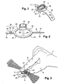
- FIG. 1 shows a device 1 according to the invention.
- This device 1 has a This means of application 2 comprises a bottom 12 and a reservoir 27 presented at an inner face 26 of the bottom 12.
- a dose of product can be stored in the reservoir 27.
- this reservoir 27 is a manually compressible chamber, ie the product stored in the tank can be externalized by compressing at least one wall 28 from this room. These walls 28 erected on the bottom 12 of the application means 2 are compressed so as to reduce the volume defined by this reservoir 27.
- the walls 28 are gradually compressed so as to deposit of the product all along the wick when the application means 2 is moved longitudinally relative to this wick.
- the device 1 comprises at least one attachment means 5 to be mounted on to minus one finger 9 of one hand 7.
- the inner face 26 is opposite a face 13.
- the notions of inner 26 and outer 13 faces are defined relative to the position of the finger 9 retained by the fixing means 5 on the means 2, the outer face 13 corresponding to the finger side face 9, then that the inner face 26 corresponds to the reservoir side face 27 intended to come to the contact of the wick.
- the means of application 2 has teeth 25 to cooperate with the wick to be coated.
- the teeth 25 on all or part of the surface proposed by the inner face 26.
- the teeth 25 are for example arranged in rows, especially near the border of this inner face 26.
- Figure 1 the rows of teeth 25 form the wall 28 and are compressible.
- the teeth 25 are preferably orthogonal to the inner face 26. They can be more or less high with each other in relation to a defined plane by this inner face 26. Especially when the teeth 25 are arranged on all or part of the periphery of this face, a central depression is defined between these teeth. Central depression can also be defined in relation to a surface delimited by all the ends of the teeth. In this case depression corresponds to the area of the inner surface 26 where the teeth are the shorter, and forms the reservoir 27. The presence of the teeth 25 can store a dose of product especially when it is pasty.
- the reservoir 27 is defined by a wall continuous 28 protruding at a bottom edge 12.
- the teeth are joined together at their base. They then form a aliasing at the edge defining the opening of the reservoir 27.
- This aliasing is for example presented on portions of curbs of the wall located substantially in the axis according to which the bit is supposed to be arranged relative to the means of application 2. in this case, the teeth 25 provide a comb function.
- the reservoir 27 has an open cylindrical shape, or a shape open parallelepiped.
- the wick is intended to be applied against the opening of this reservoir 27, as shown on the Figure 3
- the manual pressure is preferably applied orthogonally on the face outer 13 of the bottom 12. It is for example obtained by pinching.
- Figure 3 to compress the reservoir 27 and ensure its emptying on the wick, the finger 9 retained in the fixing means 5 exerts the pressure from this outer face 13, at least one second finger 8 cooperates with said finger 9 retained in the means fixing 5.
- the second finger 8 is disposed opposite the opening of the reservoir, and the wick to be coated is disposed between this second finger 8 and the opening of the reservoir 27.
- the second finger 8 corresponds to the same hand as that corresponding to that which is retained in the fixing means 5.
- the fingers selected for making the wick are for example the index finger and the thumb.
- the wall 28 of the reservoir 27 is compressible under the effect of manual pressure. In addition she is in memory of form. Indeed, after a first compression, if the pressure is released, the wall is raised to reform the reservoir 27 with its maximum interior volume. It can then be loaded again with a quantity of product to apply on a new wick.
- the reservoir 27 is for example made of a flexible material.
- a flexible material having a hardness of between 30 and 150 Shore A, and preferably with a hardness equal to 60 shore A.
- the material used is for example, chosen from polymers of SEBS (styrene-ethylene-butadiene) sequencers), or injectable thermoplastic rubbers, such as Santoprene® (supplied by Monsanto), or more generally a material thermoélastomère.
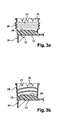
- the wall of the reservoir 27 may comprise bellows that can crush each other. on others under pressure, Figure 3a.
- the wall may be provided with a helical spring, Figure 3b, for example realized as a rib of the wall.
- the coil spring also defines preferential fold lines of the wall 28.
- a holding member 4 cooperates with directly with the opening of the reservoir 27, and the wick to be coated is arranged between this holding member 4 and this opening.
- the application means 2 and the holding member 4 are then preferably each respectively provided with a fastening means respectively 5 and 6. These means fasteners are intended to be mounted on at least two fingers of a user.
- the device 1 is then mounted on fingers of the same hand 7 of a user.
- the means of application 2 is presented on the thumb 9 of this hand 7 through the first fastening means 5.
- the holding member 4 is presented on the index 8 of this same hand 7 through the second fastening means 6.
- the holding member 4 is provided to allow better compression of the 28. Indeed, it proposes a rigid interface against which the walls 28 can lean more firmly than when applied directly to the inner face of the second finger 8.
- the opening of the reservoir 27 can thus have dimensions greater than the surface area of the inner face of this second 8. It is thus possible to simply make wicks of greater width than that of a phalanx.
- the attachment means 5 and 6 may each implement mechanisms different fixation. They are preferably made in the same way.
- the different variants of the fixing devices envisaged in the invention will be only described for the means of attachment 5.
- the variant embodiments of the fixing means 6 are derived by analogy from those of the fixing means 5, the holding member 4 being substituted, if necessary, by the application means 2.
- the fastening means 5 comprises a first leg 10 intended to cooperate with a second leg 11.
- These lugs 10 and 11 form flanges adapted to be interconnected.
- these legs 10 and 11 are define in the continuity of the bottom 12 formed by the means of application 2. In in this case, they extend in opposite directions to each other.
- These legs are planned to be flexible and can be curved towards each other above the outer face 13 of the bottom 12.
- the legs each have a connecting means complementary to each other.
- the fixing means 5 is adjustable, in particular to one dimension, for example the diameter of a finger around which it is mounted.
- the first leg 10 has several orifices such as 14 in which a protrusion 15 of the second leg can be inserted.
- the second leg 11 also has several growths such as 15.
- both tabs 10 and 11 have adjusting means.
- An outgrowth 15, as shown in Figure 1, is inserted in force in an orifice such as 14.
- the protrusion 15 is inserted without forcing, the orifice 14 presents then a shape similar to that shown in Figure 2.
- the orifice 14 presents in this case a shape corresponding to two circular openings 14 'and 14 "connected to one another by a recess 16.
- the protrusion 15 can be inserted into the opening of larger diameter 14 ', and once inserted, slide it to the level of the recess 16 so as to bring it into the opening of smaller diameter 14 " where his exit will be prevented.
- the smaller diameter orifice 14 is the farthest from the average 2. In fact, with such a configuration, since the legs are forced to be connected, they tend to want to deviate one on the other, and the maintenance of the outgrowth 15 remains in the opening of smaller diameter 14 ".
- the second leg 11 has a tubular shape elongate.
- An outgrowth 15 corresponds to a chamfered collar, one of which base 17 is of larger diameter than the diameter of the tube 11 of which it exceeds.
- the chamfer is oriented so that the base 17 is relatively closer to the means of application 2.
- the largest diameter 14 'of the opening is greater than the diameter at this base 17, and the smallest diameter 14 "of the opening is it greater than the diameter of the tube 11, but lower to that of base 17.
- the fixing means 5 is in the form of a fingerstall (not shown) in which at least one finger can be inserted.
- the fingerstall exceeds the outer face 13 of the application means 2.
- the fixing means comprises a unique paw intended to cooperate with a complementary means presented to the outer surface of the application means 2.
- the tabs 10 and 11 preferably extend in two opposite directions of a same axis 18.
- the legs extend along an axis 18 secant with the application means 2.
- the last phalanx of this finger is preferably placed at the outer face 13 of the bottom 12. This position gives greater accuracy to the application of the product capillary.
- a leg breaks down into two arches.
- the tab 10 comprises a first arc 20 and a second arc 21.
- two arcs 20 and 21 deviate from the portion of the tab having the means of connection, here in this case the orifices 14, to come attached to the means 2 in two separate points.
- the space defined between the arcs 20 and 21 can be full, which is to suggest a wider tab 10 to near the application means 2 and finer at the connecting means.
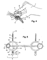
- the first arc 20 is connected to the periphery of the bottom 12 of the application means 2, and the second arc 21 is directly connected to this element link 3, as shown in FIG.
- the second leg 11 also has two arcs respectively 22 and 23, these are connected in the same way, and seen from above define with the arches 20 and 21 the outlines of a circle.
- a segment 29 then extends along a diameter of this circle, and the legs 10 and 11 extend radially, and orthogonally to this segment 29, outwardly of the circle.
- the segment 29 is disposed in the axis of the finger on which the application means 2 is mounted, and the legs surround this finger so as to be connected to the side the back of the corresponding hand.
- the means of application 2 is arranged on this segment 29.
- Figure 5 the application means 2 is arranged at a end of this segment 29.
- this segment 29 corresponds to a part of the link element 3, and the arcs can all be connected either to the connecting element 3 or the means of application 2.
- the fixing means 5 comprises a stop 24, Indeed, this abutment 24 is preferably orthogonal to the outer face 13 of the bottom 12, the abutment 24 being for example placed at the level a border of the outer face 13.
- the bottom 12 may for example have a rectangular or oval shape.
- the abutment 24 can have a rectilinear or curved shape and then present view from above a substantially U-shaped shape, the finger abutting in the hollow from U.
- the connecting element 3 is for example a connecting strip extending according to a axis 19 between the application means 2 and the holding member 4.
- the axis 18 of the legs is then for example perpendicular to this axis 19.
- the axis 18 of the legs is intersecting with the connecting element 3. The second embodiment allows a fixation around an anterior part of the end of a finger.
- the holding member 4 has a shape of flat pallet of substantially identical shape to that of the opening of the tank 27.
- the pallet is round, it has a diameter slightly greater than that of the opening of the reservoir 27.
- the holding member 4 has a left surface, covering more intimately the finger on which it is mounted. Index overlapping not naturally the thumb in a parallel fashion, this left surface allows for promote the parallel position of the holding member 4 vis-à-vis the means of application 2.
- the holding member 4 may also include teeth such as 25. In this case, these can be oriented more or less orthogonally to the palette from which they go.
- the wick is for example guided between teeth of the holding member 4 and those of the application means 2.
- the holding member 4 may also have a shape similar to that of the tank 27. In this case the holding member 4 ensures also a function of application of the product on the wick, it is then coated from two sides.
- the holding member 4 is symmetrical reservoir 27 relative to a point on the connecting strip 3, or relative to an axis orthogonally intersecting the axis 19.
- the device 1 is formed of a single piece, for example obtained by molding a flexible and flexible material.
- it may comprise several parts, in which case the connecting element 3 may be a hinge.
- the teeth 25 can be added to the medium 2 and or the holding member 4. The teeth 25 can then be made of synthetic and natural strands, these strands being for example stuck on the means of application 2.
Landscapes
- Health & Medical Sciences (AREA)
- Dermatology (AREA)
- General Health & Medical Sciences (AREA)
- Cleaning And Drying Hair (AREA)
- Coating Apparatus (AREA)
- Brushes (AREA)
- Containers And Packaging Bodies Having A Special Means To Remove Contents (AREA)
Applications Claiming Priority (4)
| Application Number | Priority Date | Filing Date | Title |
|---|---|---|---|
| FR0216577A FR2848787B1 (fr) | 2002-12-23 | 2002-12-23 | Dispositif d'application en meches d'un produit capillaire |
| FR0216578 | 2002-12-23 | ||
| FR0216577 | 2002-12-23 | ||
| FR0216578A FR2848788B1 (fr) | 2002-12-23 | 2002-12-23 | Dispositif d'application en meches d'un produit capillaire |
Publications (2)
| Publication Number | Publication Date |
|---|---|
| EP1433399A1 EP1433399A1 (fr) | 2004-06-30 |
| EP1433399B1 true EP1433399B1 (fr) | 2005-08-31 |
Family
ID=32472032
Family Applications (1)
| Application Number | Title | Priority Date | Filing Date |
|---|---|---|---|
| EP03293112A Expired - Lifetime EP1433399B1 (fr) | 2002-12-23 | 2003-12-11 | Dispositif d'application en mèches d'un produit capillaire |
Country Status (8)
Cited By (1)
| Publication number | Priority date | Publication date | Assignee | Title |
|---|---|---|---|---|
| FR2949185A1 (fr) * | 2009-08-18 | 2011-02-25 | Oreal | Applicateur de produit cosmetique, tete et dispositif associes. |
Families Citing this family (13)
| Publication number | Priority date | Publication date | Assignee | Title |
|---|---|---|---|---|
| EP1911368A1 (en) * | 2006-10-09 | 2008-04-16 | The Procter and Gamble Company | Hair treatment application system comprising an absorbent substrate |
| EP1920674B1 (en) | 2006-10-09 | 2011-04-20 | The Procter & Gamble Company | Hair treatment applicator and method |
| MX2009003478A (es) * | 2006-10-09 | 2009-04-14 | Procter & Gamble | Aplicador y metodo para el tratamiento del cabello. |
| EP2332437B1 (en) * | 2007-03-13 | 2013-05-01 | The Procter and Gamble Company | A tool for separating a hair bundle |
| MX2009013295A (es) * | 2007-06-06 | 2010-01-25 | Procter & Gamble | Estuche y metodo para aplicaciones de tratamiento para el cabello. |
| CN101677670B (zh) | 2007-06-15 | 2012-11-28 | 宝洁公司 | 用于挑染毛发的体系 |
| FR2976461B1 (fr) * | 2011-06-17 | 2013-07-12 | Oreal | Dispositif pour l'application en meches d'un produit capillaire |
| FR2984142B1 (fr) | 2011-12-20 | 2013-12-20 | Oreal | Composition comprenant un polymere acrylique particulier et copolymere silicone, procede de traitement des fibres keratiniques le mettant en oeuvre |
| FR2984089B1 (fr) * | 2011-12-20 | 2014-01-10 | Oreal | Dispositif d'application comprenant une composition a base de polymere filmogene hydrophobe et un solvant volatil, procede de traitement des fibres keratiniques le mettant en oeuvre |
| FR2984143B1 (fr) | 2011-12-20 | 2014-07-11 | Oreal | Procede d'application d'une composition de coloration pigmentaire a base de polymere acrylique particulier et de copolymere silicone, et dispositif approprie |
| FR2984132B1 (fr) | 2011-12-20 | 2014-08-01 | Oreal | Composition de coloration pigmentaire a base de polymere acrylique particulier et de copolymere silicone, procede de coloration |
| FR2992559B1 (fr) | 2012-06-29 | 2014-06-20 | Oreal | Procede bicouche de coloration des fibres keratiniques |
| CH707491A2 (fr) | 2013-01-31 | 2014-07-31 | Christian Rieder | Applicateur de produit capillaire à cartouche. |
Family Cites Families (3)
| Publication number | Priority date | Publication date | Assignee | Title |
|---|---|---|---|---|
| US2722706A (en) * | 1952-09-18 | 1955-11-08 | Chopp Mary Joan | Sponge tipped rubber glove |
| DE2834801A1 (de) * | 1978-08-09 | 1980-02-21 | Lohrer | Vorrichtung zum manuellen auftragen von medien, insbesondere behandlungsmedien medizinischer, therapeutischer und/oder kosmetischer art |
| FR2443223A1 (fr) * | 1978-12-06 | 1980-07-04 | Templier Frederic | Diffuseur de fluide aux extremites des doigts |
-
2003
- 2003-12-11 AT AT03293112T patent/ATE303083T1/de not_active IP Right Cessation
- 2003-12-11 ES ES03293112T patent/ES2248716T3/es not_active Expired - Lifetime
- 2003-12-11 EP EP03293112A patent/EP1433399B1/fr not_active Expired - Lifetime
- 2003-12-11 DE DE60301477T patent/DE60301477T2/de not_active Expired - Lifetime
- 2003-12-22 CN CNB2003101147560A patent/CN1285299C/zh not_active Expired - Fee Related
- 2003-12-22 BR BR0306272-4A patent/BR0306272A/pt not_active Application Discontinuation
- 2003-12-22 KR KR10-2003-0094649A patent/KR100524244B1/ko not_active Expired - Fee Related
- 2003-12-24 JP JP2003428426A patent/JP3895723B2/ja not_active Expired - Fee Related
Cited By (1)
| Publication number | Priority date | Publication date | Assignee | Title |
|---|---|---|---|---|
| FR2949185A1 (fr) * | 2009-08-18 | 2011-02-25 | Oreal | Applicateur de produit cosmetique, tete et dispositif associes. |
Also Published As
| Publication number | Publication date |
|---|---|
| ATE303083T1 (de) | 2005-09-15 |
| KR100524244B1 (ko) | 2005-10-27 |
| JP3895723B2 (ja) | 2007-03-22 |
| DE60301477T2 (de) | 2006-06-14 |
| DE60301477D1 (de) | 2005-10-06 |
| CN1285299C (zh) | 2006-11-22 |
| ES2248716T3 (es) | 2006-03-16 |
| BR0306272A (pt) | 2004-09-21 |
| JP2004202251A (ja) | 2004-07-22 |
| KR20040057955A (ko) | 2004-07-02 |
| EP1433399A1 (fr) | 2004-06-30 |
| CN1511486A (zh) | 2004-07-14 |
Similar Documents
| Publication | Publication Date | Title |
|---|---|---|
| EP1433399B1 (fr) | Dispositif d'application en mèches d'un produit capillaire | |
| EP1726235B1 (fr) | Dispositif de conditionnement et d'application | |
| EP1726234B1 (fr) | Applicateur pour appliquer un produit sur les cils et/ou les sourcils | |
| EP0978241B1 (fr) | Dispositif pour l'application d'un produit de maquillage comportant une brosse, procédé de fabrication et applicateur | |
| CA2227902C (fr) | Ensemble de conditionnement et d'application d'un produit de maquillage de fibres keratiniques | |
| EP1623650B1 (fr) | Dispositif de conditionnement et d'application d'un produit cosmétique ou de soin | |
| EP0884008B1 (fr) | Dispositif pour l'application en mèches d'un produit capillaire | |
| EP1738894B1 (fr) | Applicateur et dispositif de conditionnement et d'application comportant un tel applicateur | |
| CA2308984C (fr) | Dispositif de conditionnement et d'application d'un produit cosmetique, notamment pour le maquillage des levres | |
| EP1070466B1 (fr) | Dispositif de conditionnement et d'application d'un produit sur les cils ou les sourcils | |
| EP1477083B2 (fr) | Applicateur et dispositif de conditionnement et d'application comportant un tel applicateur | |
| EP1787545A2 (fr) | Applicateur pinceau | |
| EP1652449A2 (fr) | Kit pour le maquillage des fibres kératiniques | |
| EP1275320A1 (fr) | Dispositif pour l'application en mèches d'un produit capillaire | |
| FR2809294A1 (fr) | Dispositif pour l'application d'un produit cosmetique ou de soin sur les fibres keratiniques, notamment les cils ou les sourcils | |
| EP1649777A2 (fr) | Dispositif de conditionnement et d'application d'un produit sur les cils ou les sourcils, notamment du mascara | |
| EP1336352B1 (fr) | Dispositif pour l'application d'un produit sur les fibres kératiniques | |
| EP1481608B1 (fr) | Dispositif de conditionnement et d'application | |
| EP1797789B1 (fr) | Applicateur à réserve de produit, notamment pour vernis à ongles | |
| EP1369056A1 (fr) | Applicateur comportant une tige reliée par une articulation à un organe de préhension et un élément d'application incliné | |
| EP1498046A1 (fr) | Dispositif applicateur moulé, moule et procédé de moulage d'un tel dispositif, et kit comportant ledit dispositif | |
| FR3058620B1 (fr) | Applicateur flexible pointu | |
| FR2976461A1 (fr) | Dispositif pour l'application en meches d'un produit capillaire | |
| EP1407685B1 (fr) | Applicateur pour appliquer un produit sur les ongles | |
| EP2938223B1 (fr) | Systeme de conditionnement et d'application d'une composition cosmetique et son utilisation |
Legal Events
| Date | Code | Title | Description |
|---|---|---|---|
| PUAI | Public reference made under article 153(3) epc to a published international application that has entered the european phase |
Free format text: ORIGINAL CODE: 0009012 |
|
| AK | Designated contracting states |
Kind code of ref document: A1 Designated state(s): AT BE BG CH CY CZ DE DK EE ES FI FR GB GR HU IE IT LI LU MC NL PT RO SE SI SK TR |
|
| AX | Request for extension of the european patent |
Extension state: AL LT LV MK |
|
| GRAP | Despatch of communication of intention to grant a patent |
Free format text: ORIGINAL CODE: EPIDOSNIGR1 |
|
| 17P | Request for examination filed |
Effective date: 20041230 |
|
| AKX | Designation fees paid |
Designated state(s): AT BE BG CH CY CZ DE DK EE ES FI FR GB GR HU IE IT LI LU MC NL PT RO SE SI SK TR |
|
| GRAS | Grant fee paid |
Free format text: ORIGINAL CODE: EPIDOSNIGR3 |
|
| GRAA | (expected) grant |
Free format text: ORIGINAL CODE: 0009210 |
|
| AK | Designated contracting states |
Kind code of ref document: B1 Designated state(s): AT BE BG CH CY CZ DE DK EE ES FI FR GB GR HU IE IT LI LU MC NL PT RO SE SI SK TR |
|
| PG25 | Lapsed in a contracting state [announced via postgrant information from national office to epo] |
Ref country code: RO Free format text: LAPSE BECAUSE OF FAILURE TO SUBMIT A TRANSLATION OF THE DESCRIPTION OR TO PAY THE FEE WITHIN THE PRESCRIBED TIME-LIMIT Effective date: 20050831 Ref country code: SI Free format text: LAPSE BECAUSE OF FAILURE TO SUBMIT A TRANSLATION OF THE DESCRIPTION OR TO PAY THE FEE WITHIN THE PRESCRIBED TIME-LIMIT Effective date: 20050831 Ref country code: EE Free format text: LAPSE BECAUSE OF FAILURE TO SUBMIT A TRANSLATION OF THE DESCRIPTION OR TO PAY THE FEE WITHIN THE PRESCRIBED TIME-LIMIT Effective date: 20050831 Ref country code: CZ Free format text: LAPSE BECAUSE OF FAILURE TO SUBMIT A TRANSLATION OF THE DESCRIPTION OR TO PAY THE FEE WITHIN THE PRESCRIBED TIME-LIMIT Effective date: 20050831 Ref country code: SK Free format text: LAPSE BECAUSE OF FAILURE TO SUBMIT A TRANSLATION OF THE DESCRIPTION OR TO PAY THE FEE WITHIN THE PRESCRIBED TIME-LIMIT Effective date: 20050831 Ref country code: FI Free format text: LAPSE BECAUSE OF FAILURE TO SUBMIT A TRANSLATION OF THE DESCRIPTION OR TO PAY THE FEE WITHIN THE PRESCRIBED TIME-LIMIT Effective date: 20050831 Ref country code: TR Free format text: LAPSE BECAUSE OF FAILURE TO SUBMIT A TRANSLATION OF THE DESCRIPTION OR TO PAY THE FEE WITHIN THE PRESCRIBED TIME-LIMIT Effective date: 20050831 Ref country code: IE Free format text: LAPSE BECAUSE OF FAILURE TO SUBMIT A TRANSLATION OF THE DESCRIPTION OR TO PAY THE FEE WITHIN THE PRESCRIBED TIME-LIMIT Effective date: 20050831 Ref country code: AT Free format text: LAPSE BECAUSE OF FAILURE TO SUBMIT A TRANSLATION OF THE DESCRIPTION OR TO PAY THE FEE WITHIN THE PRESCRIBED TIME-LIMIT Effective date: 20050831 Ref country code: NL Free format text: LAPSE BECAUSE OF FAILURE TO SUBMIT A TRANSLATION OF THE DESCRIPTION OR TO PAY THE FEE WITHIN THE PRESCRIBED TIME-LIMIT Effective date: 20050831 |
|
| REG | Reference to a national code |
Ref country code: CH Ref legal event code: EP Ref country code: GB Ref legal event code: FG4D Free format text: NOT ENGLISH |
|
| REG | Reference to a national code |
Ref country code: IE Ref legal event code: FG4D Free format text: LANGUAGE OF EP DOCUMENT: FRENCH |
|
| REF | Corresponds to: |
Ref document number: 60301477 Country of ref document: DE Date of ref document: 20051006 Kind code of ref document: P |
|
| PG25 | Lapsed in a contracting state [announced via postgrant information from national office to epo] |
Ref country code: BG Free format text: LAPSE BECAUSE OF FAILURE TO SUBMIT A TRANSLATION OF THE DESCRIPTION OR TO PAY THE FEE WITHIN THE PRESCRIBED TIME-LIMIT Effective date: 20051130 Ref country code: DK Free format text: LAPSE BECAUSE OF FAILURE TO SUBMIT A TRANSLATION OF THE DESCRIPTION OR TO PAY THE FEE WITHIN THE PRESCRIBED TIME-LIMIT Effective date: 20051130 Ref country code: GR Free format text: LAPSE BECAUSE OF FAILURE TO SUBMIT A TRANSLATION OF THE DESCRIPTION OR TO PAY THE FEE WITHIN THE PRESCRIBED TIME-LIMIT Effective date: 20051130 Ref country code: SE Free format text: LAPSE BECAUSE OF FAILURE TO SUBMIT A TRANSLATION OF THE DESCRIPTION OR TO PAY THE FEE WITHIN THE PRESCRIBED TIME-LIMIT Effective date: 20051130 |
|
| PG25 | Lapsed in a contracting state [announced via postgrant information from national office to epo] |
Ref country code: CY Free format text: LAPSE BECAUSE OF FAILURE TO SUBMIT A TRANSLATION OF THE DESCRIPTION OR TO PAY THE FEE WITHIN THE PRESCRIBED TIME-LIMIT Effective date: 20051211 |
|
| GBT | Gb: translation of ep patent filed (gb section 77(6)(a)/1977) | ||
| PG25 | Lapsed in a contracting state [announced via postgrant information from national office to epo] |
Ref country code: BE Free format text: LAPSE BECAUSE OF NON-PAYMENT OF DUE FEES Effective date: 20051231 Ref country code: LU Free format text: LAPSE BECAUSE OF NON-PAYMENT OF DUE FEES Effective date: 20051231 Ref country code: MC Free format text: LAPSE BECAUSE OF NON-PAYMENT OF DUE FEES Effective date: 20051231 |
|
| PG25 | Lapsed in a contracting state [announced via postgrant information from national office to epo] |
Ref country code: PT Free format text: LAPSE BECAUSE OF FAILURE TO SUBMIT A TRANSLATION OF THE DESCRIPTION OR TO PAY THE FEE WITHIN THE PRESCRIBED TIME-LIMIT Effective date: 20060222 |
|
| NLV1 | Nl: lapsed or annulled due to failure to fulfill the requirements of art. 29p and 29m of the patents act | ||
| PG25 | Lapsed in a contracting state [announced via postgrant information from national office to epo] |
Ref country code: HU Free format text: LAPSE BECAUSE OF FAILURE TO SUBMIT A TRANSLATION OF THE DESCRIPTION OR TO PAY THE FEE WITHIN THE PRESCRIBED TIME-LIMIT Effective date: 20060301 |
|
| REG | Reference to a national code |
Ref country code: ES Ref legal event code: FG2A Ref document number: 2248716 Country of ref document: ES Kind code of ref document: T3 |
|
| REG | Reference to a national code |
Ref country code: IE Ref legal event code: FD4D |
|
| PLBE | No opposition filed within time limit |
Free format text: ORIGINAL CODE: 0009261 |
|
| STAA | Information on the status of an ep patent application or granted ep patent |
Free format text: STATUS: NO OPPOSITION FILED WITHIN TIME LIMIT |
|
| 26N | No opposition filed |
Effective date: 20060601 |
|
| BERE | Be: lapsed |
Owner name: L'OREAL Effective date: 20051231 |
|
| REG | Reference to a national code |
Ref country code: CH Ref legal event code: PL |
|
| PG25 | Lapsed in a contracting state [announced via postgrant information from national office to epo] |
Ref country code: LI Free format text: LAPSE BECAUSE OF NON-PAYMENT OF DUE FEES Effective date: 20071231 Ref country code: CH Free format text: LAPSE BECAUSE OF NON-PAYMENT OF DUE FEES Effective date: 20071231 |
|
| PGFP | Annual fee paid to national office [announced via postgrant information from national office to epo] |
Ref country code: ES Payment date: 20100113 Year of fee payment: 7 Ref country code: FR Payment date: 20091221 Year of fee payment: 7 Ref country code: GB Payment date: 20091209 Year of fee payment: 7 Ref country code: IT Payment date: 20091221 Year of fee payment: 7 |
|
| PGFP | Annual fee paid to national office [announced via postgrant information from national office to epo] |
Ref country code: DE Payment date: 20091203 Year of fee payment: 7 |
|
| GBPC | Gb: european patent ceased through non-payment of renewal fee |
Effective date: 20101211 |
|
| REG | Reference to a national code |
Ref country code: FR Ref legal event code: ST Effective date: 20110831 |
|
| PG25 | Lapsed in a contracting state [announced via postgrant information from national office to epo] |
Ref country code: FR Free format text: LAPSE BECAUSE OF NON-PAYMENT OF DUE FEES Effective date: 20110103 |
|
| REG | Reference to a national code |
Ref country code: DE Ref legal event code: R119 Ref document number: 60301477 Country of ref document: DE Effective date: 20110701 |
|
| PG25 | Lapsed in a contracting state [announced via postgrant information from national office to epo] |
Ref country code: GB Free format text: LAPSE BECAUSE OF NON-PAYMENT OF DUE FEES Effective date: 20101211 Ref country code: DE Free format text: LAPSE BECAUSE OF NON-PAYMENT OF DUE FEES Effective date: 20110701 |
|
| PG25 | Lapsed in a contracting state [announced via postgrant information from national office to epo] |
Ref country code: IT Free format text: LAPSE BECAUSE OF NON-PAYMENT OF DUE FEES Effective date: 20101211 |
|
| REG | Reference to a national code |
Ref country code: ES Ref legal event code: FD2A Effective date: 20120220 |
|
| PG25 | Lapsed in a contracting state [announced via postgrant information from national office to epo] |
Ref country code: ES Free format text: LAPSE BECAUSE OF NON-PAYMENT OF DUE FEES Effective date: 20101212 |