EP1433399A1 - Dispositif d'application en mèches d'un produit capillaire - Google Patents
Dispositif d'application en mèches d'un produit capillaire Download PDFInfo
- Publication number
- EP1433399A1 EP1433399A1 EP03293112A EP03293112A EP1433399A1 EP 1433399 A1 EP1433399 A1 EP 1433399A1 EP 03293112 A EP03293112 A EP 03293112A EP 03293112 A EP03293112 A EP 03293112A EP 1433399 A1 EP1433399 A1 EP 1433399A1
- Authority
- EP
- European Patent Office
- Prior art keywords
- reservoir
- holding member
- finger
- fixing means
- wick
- Prior art date
- Legal status (The legal status is an assumption and is not a legal conclusion. Google has not performed a legal analysis and makes no representation as to the accuracy of the status listed.)
- Granted
Links
Images


Classifications
-
- A—HUMAN NECESSITIES
- A45—HAND OR TRAVELLING ARTICLES
- A45D—HAIRDRESSING OR SHAVING EQUIPMENT; EQUIPMENT FOR COSMETICS OR COSMETIC TREATMENTS, e.g. FOR MANICURING OR PEDICURING
- A45D8/00—Hair-holding devices; Accessories therefor
- A45D8/004—Hair-holding devices; Accessories therefor with decorative arrangements or form
- A45D8/006—Interchangeable ornaments attached to hair holding devices
-
- A—HUMAN NECESSITIES
- A45—HAND OR TRAVELLING ARTICLES
- A45D—HAIRDRESSING OR SHAVING EQUIPMENT; EQUIPMENT FOR COSMETICS OR COSMETIC TREATMENTS, e.g. FOR MANICURING OR PEDICURING
- A45D19/00—Devices for washing the hair or the scalp; Similar devices for colouring the hair
-
- A—HUMAN NECESSITIES
- A45—HAND OR TRAVELLING ARTICLES
- A45D—HAIRDRESSING OR SHAVING EQUIPMENT; EQUIPMENT FOR COSMETICS OR COSMETIC TREATMENTS, e.g. FOR MANICURING OR PEDICURING
- A45D19/00—Devices for washing the hair or the scalp; Similar devices for colouring the hair
- A45D19/0041—Processes for treating the hair of the scalp
- A45D19/0066—Coloring or bleaching
-
- A—HUMAN NECESSITIES
- A45—HAND OR TRAVELLING ARTICLES
- A45D—HAIRDRESSING OR SHAVING EQUIPMENT; EQUIPMENT FOR COSMETICS OR COSMETIC TREATMENTS, e.g. FOR MANICURING OR PEDICURING
- A45D19/00—Devices for washing the hair or the scalp; Similar devices for colouring the hair
- A45D19/02—Hand-actuated implements, e.g. hand-actuated spray heads
- A45D19/024—Hand-actuated implements, e.g. hand-actuated spray heads comprising two clamping surfaces for insertion of hair there between
-
- A—HUMAN NECESSITIES
- A45—HAND OR TRAVELLING ARTICLES
- A45D—HAIRDRESSING OR SHAVING EQUIPMENT; EQUIPMENT FOR COSMETICS OR COSMETIC TREATMENTS, e.g. FOR MANICURING OR PEDICURING
- A45D19/00—Devices for washing the hair or the scalp; Similar devices for colouring the hair
- A45D19/02—Hand-actuated implements, e.g. hand-actuated spray heads
- A45D19/026—Hand-actuated implements, e.g. hand-actuated spray heads having brush or comb applicators
Definitions
- the present invention relates to a device for applying wicks of a hair product.
- the device according to the invention is very particularly suitable to allow a self-application of a coloring product on locks.
- “Wicking” coloring is a treatment where only certain parts of the hair are soaked with coloring product, in order to obtain, once the finished treatment, a non-homogeneous color effect, thus highlighting such and such movement of the hair with lighter or more shades of color darker than the natural or overall shade of the hair.
- hair coloring products coloring temporary, semi-permanent coloring, permanent so-called oxidation coloring.
- All these coloring products can be in the form of cream, foam, or liquid of higher or lower viscosity.
- the products of coloring in liquid or gel form can be applied, possibly after mixture, from a porous medium, such as a foam.
- a porous medium such as a foam.
- the products the most viscous and the pasty are presented in bowls after mixing a bleaching powder and an oxidant in said bowl.
- Such devices generally suffer from the same drawbacks, linked to the fact that they are used by attacking the hair from its side outside, ie on top.
- the product is deposited mainly on the wick surface, and little inside, the applicator then being moved relatively to the wick, from the root to the tip.
- Now during this movement experience shows that the user tends to lift the applicator and make it leave a trajectory along the curvature of the skull.
- a certain number of hairs detach from the applicator to fall back on the hair. This hair will therefore not be colored, in the case of a coloring product. The result obtained is therefore far from satisfactory.
- the object of the invention is to remedy the problems mentioned above by proposing a device facilitating self-application "in wicks" of a hair product.
- the device according to the invention comprises a means of applying the product of hair treatment provided with a fixing means to be presented at the level of one end of a finger.
- the finger is for example pressed by the means of fixing against an external face of a flat bottom of the means application.
- the application means which comprises a manually compressible reservoir.
- the reservoir of application means can hold a dose of product and release it following compression of one of its walls. Indeed, walls of this tank can be at least partially compressed to reduce their height relative to the fixing means.
- the reservoir can in particular be compressed as and measurement of longitudinal displacement along the drill bit by sliding roots towards the tips.
- the wick is advantageously impregnated in a uniform manner, without depositing of packages although the product is pasty, and the width of the wicks thus produced is easily reproducible, allowing a result to be obtained homogeneous throughout the hair.
- the application means comprises teeth
- These teeth are also compressible.
- the wick is for example physically pinched between an opening of the reservoir of the means of application and at least one other finger of the hand.
- a force of compression is applied at the bottom of the tank, through at minus one finger presented in the fixing means on an external face of this bottom, the reservoir being compressed between the at least one finger and the other finger of the hand.
- the tank can be compressed so that pinching is exerted laterally on a wall delimiting the opening at the level of which the wick is presented.
- the fixing means is adjustable to the diameter of the finger on which it is mounted.
- it comprises for example two legs capable of being interconnected.
- a first leg can be designed to be inserted into an opening in a second tab, one of the tabs having several levels for fixing the first leg with the second leg.
- the two legs allow the fixing of the means of attachment around an anterior part of the finger.
- At least one leg has two arches.
- the two arcs are attached to the level of the medium application, and join to be able to be connected jointly to the second paw.
- the position of the arcs also provides greater stability of the means of application on the underside of the finger around which it is mounted.
- the means of application has a stop on an outer periphery, to limit the penetration of the finger in the fixing means.
- the device according to the invention forms a single piece, for example obtained by molding.
- a support which also serves as a support for presenting the wick opposite and against an opening of the tank.
- This holding member can be retained on the other finger by a fixing means similar to that of the application means.
- the application means is connected to the member holding by a connecting element, preferably a flexible strip.
- the holding member cooperates with an opening of this reservoir. Indeed, the holding member can be folded over the opening, so that the wick is caught between the opening of the reservoir and this holding member.
- the pressure is then exerted on an outer periphery both of the bottom of the tank and respectively an outer periphery of the holding member. The pressure is obtained by pinching between the at least two fingers, for example between the thumb and the index finger of the same hand.
- the means of application and or the holding member comprises teeth intended to cooperate with the wick.
- the holding can be achieved so as to form a second application means.
- the second means is also capable of retaining product.
- the two application means are then pressed one towards the other, on the one hand and on the other side of the wick.
- the wick is thus better impregnated with product.
- the holding member is the symmetrical of the application means relative to an axis orthogonally cutting the connecting element which connects them.
- a wall of the reservoir is compressible in response to a force exerted orthogonally relative to a bottom at which the means attachment is presented.
- a wall of the reservoir is formed by teeth erect relative to a bottom, these teeth delimiting a central depression defined with respect to a surface delimited by all the ends of the teeth.
- a wall of the reservoir forms a bellows, for example provided a shape memory coil spring.
- the fixing means can be adjustable according to a dimension at least one finger around which it is mounted.
- the fixing means may comprise two tabs able to be interconnected.
- the legs can extend in two directions opposite of the same axis.
- the tab (s) extend (s) in a plane formed by a bottom of the tank.
- a tab is attached by at least two arcs at the bottom of the tank.
- the two arcs can be elastically deformable.
- the fixing means may comprise a stop on a periphery outside of the reservoir to limit the penetration of the finger relative to the means of fixation.
- the device may include a holding member capable to cooperate with the reservoir to maintain the wick in engagement with the reservoir so as to allow its coating with said product.
- the holding member can be folded over an opening of the tank, the wick being taken between this opening and the holding member, the pressure exerted on the tank being obtained by pinching between a bottom of the tank and the holding member on either side of the wick.
- the organ of support comprises a plate of dimension greater than an opening of the tank.
- the holding member may include teeth.
- the holding member can be identical to the application means.
- the holding member also comprises a second means fixing intended to allow its fixing on at least a second finger.
- the second fastening means may include at least one tab elastically deformable able to be held at least partially around said second finger.
- this second fixing means may include at least two elastically deformable legs capable of being interconnected.
- the holding member can be connected by a connecting strip flexible to the tank.
- the tab (s) can extend orthogonally to the flexible strip.
- the device can be formed from a single piece, for example obtained by molding.
- FIG. 1 shows a device 1 according to the invention.
- This device 1 includes a application means 2.
- This application means 2 comprises a bottom 12 and a reservoir 27 presented at an inner face 26 of this bottom 12.
- a dose product can be stored in the tank 27.
- this tank 27 is a manually compressible chamber, i.e. the stored product in the tank can be outsourced by compression of at least one wall 28 from this room. These walls 28 erected on the bottom 12 of the application means 2 are compressed so as to reduce the volume defined by this reservoir 27.
- the walls 28 are progressively compressed so as to deposit of the product all along the wick when the application means 2 is moved longitudinally relative to this wick.
- the device 1 comprises at least one fixing means 5 to be mounted on at minus one finger 9 of one hand 7.
- the inner face 26 is opposite a face exterior 13.
- the concepts of interior 26 and exterior 13 are defined relative to the position of the finger 9 retained by the fixing means 5 on the means 2, the outer face 13 corresponding to the face on the finger side 9, then that the inner face 26 corresponds to the face on the reservoir side 27 intended to come to the wick contact.
- the means of application 2 has teeth 25 to cooperate with the wick to be coated.
- Teeth 25 stand on all or part of the surface proposed by the internal face 26.
- the teeth 25 are for example arranged in rows, in particular near the edge of this inner face 26.
- Figure 1 the rows of teeth 25 form the wall 28 and are compressible.
- the teeth 25 are preferably erected orthogonally to the inner face 26. They can be higher or lower between them relative to a defined plane by this inner face 26. In particular when the teeth 25 are arranged on all or part of the periphery of this face, a central depression is defined between those teeth. Central depression can also be defined in relation to a surface delimited by all the ends of the teeth. In this case depression corresponds to the area of the inner surface 26 where the teeth are the shorter, and forms the reservoir 27. The presence of the teeth 25 makes it possible to store a dose of product, especially when it is pasty.
- the reservoir 27 is defined by a wall continuous 28 protruding at the edge of the bottom 12.
- the teeth are therefore joined together at their base. They then form a aliasing at the edge defining the opening of the reservoir 27.
- This aliasing is for example presented on portions of edges of the wall situated substantially in the axis along which the wick is supposed to be arranged relative to the application means 2.
- the teeth 25 provide a comb function.
- the reservoir 27 has an open cylindrical shape, or a shape open parallelepiped. In all cases the wick is intended to be applied against the opening of this reservoir 27, as shown in the Figure 3.
- Manual pressure is preferably exerted orthogonally on the face outer 13 of the bottom 12. It is for example obtained by pinching.
- Figure 3 to compress the reservoir 27 and ensure its emptying on the wick, the finger 9 retained in the fixing means 5 exerts pressure from this outer face 13, at least one second finger 8 cooperates with said finger 9 retained in the means fixing 5.
- the second finger 8 is disposed opposite the opening of the reservoir, and the wick to be coated is disposed between this second finger 8 and the opening of the reservoir 27.
- the second finger 8 corresponds to the same hand as that corresponding to that which is retained in the fixing means 5.
- the fingers chosen to make the wick are for example the index finger and the thumb.
- the wall 28 of the reservoir 27 is compressible under the effect of manual pressure. In addition, it has shape memory. Indeed, after a first compression, if the pressure is released, the wall straightens to reform the reservoir 27 with its maximum interior volume. It can then be charged again with a quantity of product to apply on a new wick.
- the reservoir 27 is for example made of a flexible material.
- a flexible material having a hardness between 30 and 150 Shore A, and preferably with a hardness equal to 60 shore A.
- the material used is for example chosen from SEBS polymers (styrene - ethylene - butadiene sequenced), or injectable thermo-plastic rubbers, such as Santoprene® (supplied by Monsanto), or more generally a material thermoélastomère.
- the wall of the reservoir 27 may include bellows which can crush each other on the others under the effect of pressure, Figure 3a.
- the wall can be provided with a helical spring, Figure 3b, for example made as a wall rib.
- the coil spring also defines preferential fold lines of the wall 28.
- a holding member 4 cooperates directly with the opening of the reservoir 27, and the wick to be coated is arranged between this holding member 4 and this opening.
- the application means 2 and the holding member 4 are then preferably each respectively provided with a fixing means 5 and 6 respectively. These means fasteners are intended to be mounted on at least two fingers of a user.
- the device 1 is then mounted on fingers of the same hand 7 of a user.
- Application means 2 is presented on thumb 9 of this hand 7 by means of the first fastening means 5.
- the holding member 4 is presented on the index 8 of this same hand 7 by means of the second fixing means 6.
- the holding member 4 is provided to allow better compression of the walls 28. Indeed, it offers a rigid interface against which the walls 28 can rest more firmly than when applied directly to the inner face of the second finger 8.
- the opening of the reservoir 27 can thus have dimensions greater than the area of the internal face of this second finger 8. We can thus simply make wicks wider than that of a phalanx.
- the fastening means 5 and 6 can each implement mechanisms different fixing. They are preferably made in the same way.
- the different variants of the fixing devices envisaged in the invention will be only described for the fixing means 5.
- the variant embodiments of the fastening means 6 are deduced by analogy from those of fastening means 5, the holding member 4 being to be replaced if necessary by the application means 2.
- the fixing means 5 comprises a first tab 10 intended to cooperate with a second tab 11.
- These tabs 10 and 11 form flanges capable of being connected together.
- these legs 10 and 11 are define in the continuity of the bottom 12 formed by the application means 2. In in this case, they extend in opposite directions to each other.
- These legs are designed to be flexible and can be curved one towards the other above the outer face 13 of the bottom 12.
- the legs each have a connecting means complementary to each other.
- the fixing means 5 is adjustable, in particular to one dimension, for example the diameter, of a finger around which it is mounted.
- the first tab 10 has several orifices such as 14 in which a protuberance 15 of the second leg can be inserted.
- the second tab 11 also has several growths such as 15.
- the two tabs 10 and 11 have adjustment means.
- a protuberance 15, as shown in Figure 1, is inserted in force in an opening such as 14.
- the protuberance 15 is inserted without forcing, the orifice 14 has then a shape similar to that presented in Figure 2.
- the orifice 14 present in this case a shape corresponding to two circular openings 14 'and 14 "connected to each other by a recess 16.
- the protrusion 15 can be inserted into the opening of larger diameter 14 ', and once inserted, slide it to the level of the recess 16 so as to bring it into the opening of smaller diameter 14 " where its exit will be prevented.
- the hole of smaller diameter 14 " is furthest from the means Application 2. Indeed, with such a configuration, insofar as the legs are constrained to be connected, these tend to want to deviate from one on the other, and maintaining the protrusion 15 remains in the opening of smaller diameter 14 ".
- the second tab 11 has a tubular shape elongate.
- a protuberance 15 corresponds to a chamfered flange, one of which base 17 is larger in diameter than the diameter of the tube 11 from which it exceeds.
- the chamfer is oriented so that the base 17 is relatively the closest to the application means 2.
- the largest diameter 14 'of the opening is greater than the diameter at this base 17, and the smallest diameter 14 "of the opening is greater than the diameter of the tube 11, but less to that of base 17.
- the fixing means 5 is in the form of a finger crib (not shown) into which at least one finger can be inserted.
- the finger-stick protrudes from the outer face 13 of the application means 2.
- the fixing means comprises a single leg intended to cooperate with a complementary means presented in the external surface of the application means 2.
- the legs 10 and 11 preferably extend in two opposite directions of a same axis 18.
- the legs extend along an axis 18 intersecting with the application means 2.
- the last phalanx of this finger is preferably placed at the level of the external face 13 of the bottom 12. This position gives greater precision to the application of the product capillary.
- one leg is divided into two arcs.
- the tab 10 has a first arc 20 and a second arc 21.
- the two arcs 20 and 21 move away from the portion of the tab having the means of connection, here in this case the orifices 14, to come to be attached by means application 2 at two separate points.
- the space defined between the arcs 20 and 21 can be full, which amounts to proposing a wider tab 10 to proximity of the application means 2 and finer at the connection means.
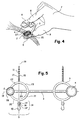
- the first arc 20 is connected to the periphery of the bottom 12 of the application means 2, and the second arc 21 is connected directly to this element link 3, as shown in Figure 5.
- the second tab 11 also has two arcs 22 and 23 respectively, these are connected in the same way, and seen from above delimit with the arcs 20 and 21 the contours of a circle.
- a segment 29 then extends along a diameter of this circle, and the legs 10 and 11 extend radially, and orthogonally to this segment 29, towards the outside of the circle.
- the segment 29 is disposed in the axis of the finger on which the application means 2 is mounted, and the legs surround this finger so as to be connected on the side on the back of the corresponding hand.
- the application means 2 is arranged on this segment 29.
- Figure 5 the application means 2 is arranged at a end of this segment 29.
- this segment 29 corresponds to part of the connecting element 3, and the arcs can all be connected either to the connecting element 3, or by means application 2.
- the fixing means 5 comprises a stop 24, Figure 3. Indeed, this stop 24 preferably stands orthogonally to the outer face 13 of the bottom 12, the stop 24 being for example placed at the level an edge of the outer face 13.
- the bottom 12 can for example have a rectangular or oval shape.
- the stop 24 may have a straight or curved shape and then present view from above a substantially U shape, the finger abutting in the hollow from the U.
- the connecting element 3 is for example a connecting strip extending in a axis 19 between the application means 2 and the holding member 4.
- the axis 18 of legs is then for example perpendicular to this axis 19.
- the axis 18 of the legs is intersecting with the connecting element 3. The second embodiment allows fixing around of an anterior part of the end of a finger.
- the holding member 4 has a form of flat pallet of substantially identical shape to that of the tank opening 27.
- the pallet is round, it has a diameter slightly higher than that of the tank opening 27.
- Pinching namely the bringing the two fingers together, makes it possible to compress the walls of the reservoir between the bottom 12 and the pallet. The circumference of the opening is notched so as to let out the product while the walls of the tank are gradually compressed.
- the holding member 4 has a left surface, more intimately covering the finger on which it is mounted.
- the index not covering not naturally the thumb in parallel, this left surface allows favor the parallel position of the holding member 4 vis-à-vis the means application 2.
- the holding member 4 can also include teeth such as 25. In this case, these can be oriented more or less orthogonally to the palette they exceed.
- the wick is for example guided between teeth of the holding member 4 and those of the application means 2.
- the holding member 4 may also have a shape similar to that of the reservoir 27. In this case the holding member 4 ensures also a function of applying the product to the wick, this is then coated from two sides.
- the holding member 4 is the symmetrical of the reservoir 27 relative to a point located on the connecting strip 3, or relative to an axis orthogonally cutting the axis 19.
- the device 1 is formed from a single piece, for example obtained by molding a flexible and flexible material. Alternatively, it may include several parts, in which case the connecting element 3 may be a hinge.
- the teeth 25 can be added on the means application 2 and or the holding member 4. The teeth 25 can then be made of synthetic and or natural strands, these strands being for example bonded to the application means 2.
Landscapes
- Health & Medical Sciences (AREA)
- Dermatology (AREA)
- General Health & Medical Sciences (AREA)
- Cleaning And Drying Hair (AREA)
- Coating Apparatus (AREA)
- Brushes (AREA)
- Containers And Packaging Bodies Having A Special Means To Remove Contents (AREA)
Abstract
Description
Pour obtenir une diffusion progressive du produit contenu dans le réservoir, l'organe de maintien coopère avec une ouverture de ce réservoir. En effet, l'organe de maintien peut être rabattu sur l'ouverture, de telle sorte que la mèche soit prise entre l'ouverture du réservoir et cet organe de maintien. La pression est alors exercée sur un pourtour extérieur à la fois du fond du réservoir et respectivement un pourtour extérieur de l'organe de maintien. La pression est obtenue par pincement entre les au moins deux doigts, par exemple entre le pouce et l'index d'une même main.
- Figure 1: une vue en perspective d'un dispositif selon l'invention;
- Figure 2 : une vue en perspective d'un deuxième mode de réalisation du dispositif selon l'invention;
- Figure 3: une vue en perspective d'un mode d'utilisation du dispositif selon l'invention;
- Figure 3a : une vue de profil en coupe d'un premier mode de réalisation d'un réservoir du dispositif selon l'invention;
- Figure 3b : une vue de profil en coupe d'un deuxième mode de réalisation d'un réservoir du dispositif selon l'invention;
- Figure 4: une vue en perspective d'un mode préféré d'utilisation du dispositif selon l'invention;
- Figure 5 : une vue de dessus d'un mode préféré de réalisation d'un dispositif selon l'invention.
Claims (22)
- Dispositif (1) pour l'application en mèches d'un produit capillaire comportant :caractérisé en ce que le moyen de fixation comporte au moins une patte (10, 11) élastiquement déformable apte à être maintenue au moins en partie autour dudit au moins un doigt, et en ce que le moyen d'application comporte un réservoir (27) compressible permettant de libérer, notamment lors d'un déplacement longitudinal du dispositif relativement à une mèche, la quantité dudit produit sur ladite mèche en réponse à une pression manuelle exercée sur ledit réservoir.i) un moyen d'application (2) apte à retenir une quantité dudit produit capillaire, etii) au moins un moyen de fixation (5) présenté par le moyen d'application, et destiné à en permettre sa fixation sur au moins un doigt (9) d'une main (7),
- Dispositif selon la revendication 1 caractérisé en ce qu'une paroi (28) du réservoir est compressible en réponse à une force exercée orthogonalement relativement à un fond (12) au niveau duquel le moyen de fixation est présenté.
- Dispositif selon la revendication 1 ou 2 caractérisé en ce qu'une paroi du réservoir est formée par des dents (25) dressées relativement à un fond, ces dents délimitant une dépression centrale définie par rapport à une surface délimitée par l'ensemble des extrémités des dents.
- Dispositif selon l'une quelconque des revendications 1 à 3 caractérisé en ce qu'une paroi du réservoir forme un soufflet, par exemple munie d'un ressort hélicoïdal à mémoire de forme.
- Dispositif selon l'une quelconque des revendications 1 à 4 caractérisé en ce que le moyen de fixation est ajustable en fonction d'une dimension du au moins un doigt autour duquel il est monté.
- Dispositif selon l'une quelconque des revendications 1 à 5 caractérisé en ce que le moyen de fixation comporte deux pattes (10, 11) aptes à être reliées entre elles.
- Dispositif selon la revendication 6 caractérisé en ce que les pattes s'étendent selon deux directions opposées d'un même axe (18).
- Dispositif selon l'une quelconque des revendications 1 à 7, caractérisé en ce que la ou les patte(s) s'étend(ent) dans un plan formé par un fond du réservoir.
- Dispositif selon l'une quelconque des revendications 1 à 8, caractérisé en ce qu'une patte est rattachée par au moins deux arcs (20, 21, 22, 23) au fond du réservoir.
- Dispositif selon la revendication 9 caractérisé en ce que les deux arcs (20, 21, 22, 23) sont élastiquement déformables.
- Dispositif selon l'une quelconque des revendications 1 à 10 caractérisé en ce que le moyen de fixation comporte une butée (24) sur un pourtour extérieur du réservoir pour limiter l'enfoncement du doigt relativement au moyen de fixation.
- Dispositif selon l'une quelconque des revendications 1 à 11 caractérisé en ce qu'il comporte un organe de maintien (4) apte à coopérer avec le réservoir pour maintenir la mèche en engagement avec le réservoir de manière à en permettre son enduction avec ledit produit.
- Dispositif selon la revendication 12 caractérisé en ce que l'organe de maintien peut être rabattu sur une ouverture du réservoir, la mèche étant prise entre cette ouverture et l'organe de maintien, la pression exercée sur le réservoir étant obtenue par pincement entre un fond du réservoir et l'organe de maintien de part et d'autre de la mèche.
- Dispositif selon la revendication 12 ou 13 caractérisé en ce que l'organe de maintien comporte une plaque de dimension supérieure à une ouverture du réservoir.
- Dispositif selon la revendication 12 ou 14 caractérisé en ce que l'organe de maintien comporte des dents.
- Dispositif selon la revendication 12 ou 15 caractérisé en ce que l'organe de maintien est identique au moyen d'application.
- Dispositif selon l'une quelconque des revendications 12 à 16 caractérisé en ce que l'organe de maintien comporte un deuxième moyen de fixation (6) destiné à en permettre sa fixation sur au moins un deuxième doigt.
- Dispositif selon la revendication 17 caractérisé en ce que le deuxième moyen de fixation comporte au moins une patte élastiquement déformable apte à être maintenue au moins en partie autour dudit deuxième doigt.
- Dispositif selon l'une quelconque des revendications 17 à 18 caractérisé en ce que le deuxième moyen de fixation comporte au moins deux pattes élastiquement déformables aptes à être reliées entre elles.
- Dispositif selon l'une quelconque des revendications 12 à 19 caractérisé en ce que l'organe de maintien est relié par une bande de liaison souple au réservoir.
- Dispositif selon la revendication 20 caractérisé en ce que la ou les pattes s'étend(ent) orthogonalement à la bande souple.
- Dispositif selon l'une quelconque des revendications 1 à 21 caractérisé en ce qu'il forme une pièce unique, par exemple obtenue par moulage.
Applications Claiming Priority (4)
| Application Number | Priority Date | Filing Date | Title |
|---|---|---|---|
| FR0216577 | 2002-12-23 | ||
| FR0216578A FR2848788B1 (fr) | 2002-12-23 | 2002-12-23 | Dispositif d'application en meches d'un produit capillaire |
| FR0216577A FR2848787B1 (fr) | 2002-12-23 | 2002-12-23 | Dispositif d'application en meches d'un produit capillaire |
| FR0216578 | 2002-12-23 |
Publications (2)
| Publication Number | Publication Date |
|---|---|
| EP1433399A1 true EP1433399A1 (fr) | 2004-06-30 |
| EP1433399B1 EP1433399B1 (fr) | 2005-08-31 |
Family
ID=32472032
Family Applications (1)
| Application Number | Title | Priority Date | Filing Date |
|---|---|---|---|
| EP03293112A Expired - Lifetime EP1433399B1 (fr) | 2002-12-23 | 2003-12-11 | Dispositif d'application en mèches d'un produit capillaire |
Country Status (8)
| Country | Link |
|---|---|
| EP (1) | EP1433399B1 (fr) |
| JP (1) | JP3895723B2 (fr) |
| KR (1) | KR100524244B1 (fr) |
| CN (1) | CN1285299C (fr) |
| AT (1) | ATE303083T1 (fr) |
| BR (1) | BR0306272A (fr) |
| DE (1) | DE60301477T2 (fr) |
| ES (1) | ES2248716T3 (fr) |
Cited By (4)
| Publication number | Priority date | Publication date | Assignee | Title |
|---|---|---|---|---|
| WO2008044199A1 (fr) * | 2006-10-09 | 2008-04-17 | The Procter & Gamble Company | Applicateur et procédé de traitement capillaire |
| EP2005854A1 (fr) | 2007-06-15 | 2008-12-24 | The Procter & Gamble | Système pour créer des mèches dans la chevelure |
| WO2014118348A1 (fr) | 2013-01-31 | 2014-08-07 | Lockstyler Sa | Applicateur de produits capillaires |
| US9681725B2 (en) | 2009-08-18 | 2017-06-20 | L'oreal | Cosmetic product applicator, associated head and device |
Families Citing this family (10)
| Publication number | Priority date | Publication date | Assignee | Title |
|---|---|---|---|---|
| JP5266230B2 (ja) * | 2006-10-09 | 2013-08-21 | ザ プロクター アンド ギャンブル カンパニー | 毛髪処理用塗布器及び方法 |
| EP1911368A1 (fr) * | 2006-10-09 | 2008-04-16 | The Procter and Gamble Company | Système d'application pour le traitement des cheveux comprenant un substrat absorbant |
| EP1969961B1 (fr) * | 2007-03-13 | 2014-07-23 | The Procter and Gamble Company | Outil pour la séparation d'un faisceau de cheveux |
| AU2008259404A1 (en) * | 2007-06-06 | 2008-12-11 | The Procter & Gamble Company | Kit and method for hair treatment applications |
| FR2976461B1 (fr) * | 2011-06-17 | 2013-07-12 | Oreal | Dispositif pour l'application en meches d'un produit capillaire |
| FR2984143B1 (fr) | 2011-12-20 | 2014-07-11 | Oreal | Procede d'application d'une composition de coloration pigmentaire a base de polymere acrylique particulier et de copolymere silicone, et dispositif approprie |
| FR2984089B1 (fr) * | 2011-12-20 | 2014-01-10 | Oreal | Dispositif d'application comprenant une composition a base de polymere filmogene hydrophobe et un solvant volatil, procede de traitement des fibres keratiniques le mettant en oeuvre |
| FR2984142B1 (fr) | 2011-12-20 | 2013-12-20 | Oreal | Composition comprenant un polymere acrylique particulier et copolymere silicone, procede de traitement des fibres keratiniques le mettant en oeuvre |
| FR2984132B1 (fr) | 2011-12-20 | 2014-08-01 | Oreal | Composition de coloration pigmentaire a base de polymere acrylique particulier et de copolymere silicone, procede de coloration |
| FR2992559B1 (fr) | 2012-06-29 | 2014-06-20 | Oreal | Procede bicouche de coloration des fibres keratiniques |
Citations (3)
| Publication number | Priority date | Publication date | Assignee | Title |
|---|---|---|---|---|
| US2722706A (en) * | 1952-09-18 | 1955-11-08 | Chopp Mary Joan | Sponge tipped rubber glove |
| DE2834801A1 (de) * | 1978-08-09 | 1980-02-21 | Lohrer | Vorrichtung zum manuellen auftragen von medien, insbesondere behandlungsmedien medizinischer, therapeutischer und/oder kosmetischer art |
| FR2443223A1 (fr) * | 1978-12-06 | 1980-07-04 | Templier Frederic | Diffuseur de fluide aux extremites des doigts |
-
2003
- 2003-12-11 DE DE60301477T patent/DE60301477T2/de not_active Expired - Lifetime
- 2003-12-11 EP EP03293112A patent/EP1433399B1/fr not_active Expired - Lifetime
- 2003-12-11 ES ES03293112T patent/ES2248716T3/es not_active Expired - Lifetime
- 2003-12-11 AT AT03293112T patent/ATE303083T1/de not_active IP Right Cessation
- 2003-12-22 KR KR10-2003-0094649A patent/KR100524244B1/ko not_active Expired - Fee Related
- 2003-12-22 BR BR0306272-4A patent/BR0306272A/pt not_active Application Discontinuation
- 2003-12-22 CN CNB2003101147560A patent/CN1285299C/zh not_active Expired - Fee Related
- 2003-12-24 JP JP2003428426A patent/JP3895723B2/ja not_active Expired - Fee Related
Patent Citations (3)
| Publication number | Priority date | Publication date | Assignee | Title |
|---|---|---|---|---|
| US2722706A (en) * | 1952-09-18 | 1955-11-08 | Chopp Mary Joan | Sponge tipped rubber glove |
| DE2834801A1 (de) * | 1978-08-09 | 1980-02-21 | Lohrer | Vorrichtung zum manuellen auftragen von medien, insbesondere behandlungsmedien medizinischer, therapeutischer und/oder kosmetischer art |
| FR2443223A1 (fr) * | 1978-12-06 | 1980-07-04 | Templier Frederic | Diffuseur de fluide aux extremites des doigts |
Cited By (5)
| Publication number | Priority date | Publication date | Assignee | Title |
|---|---|---|---|---|
| WO2008044199A1 (fr) * | 2006-10-09 | 2008-04-17 | The Procter & Gamble Company | Applicateur et procédé de traitement capillaire |
| EP1920674A1 (fr) | 2006-10-09 | 2008-05-14 | The Procter and Gamble Company | Applicateur de traitement des cheveux et procédé |
| EP2005854A1 (fr) | 2007-06-15 | 2008-12-24 | The Procter & Gamble | Système pour créer des mèches dans la chevelure |
| US9681725B2 (en) | 2009-08-18 | 2017-06-20 | L'oreal | Cosmetic product applicator, associated head and device |
| WO2014118348A1 (fr) | 2013-01-31 | 2014-08-07 | Lockstyler Sa | Applicateur de produits capillaires |
Also Published As
| Publication number | Publication date |
|---|---|
| ES2248716T3 (es) | 2006-03-16 |
| JP2004202251A (ja) | 2004-07-22 |
| BR0306272A (pt) | 2004-09-21 |
| CN1285299C (zh) | 2006-11-22 |
| DE60301477T2 (de) | 2006-06-14 |
| KR20040057955A (ko) | 2004-07-02 |
| EP1433399B1 (fr) | 2005-08-31 |
| CN1511486A (zh) | 2004-07-14 |
| DE60301477D1 (de) | 2005-10-06 |
| JP3895723B2 (ja) | 2007-03-22 |
| KR100524244B1 (ko) | 2005-10-27 |
| ATE303083T1 (de) | 2005-09-15 |
Similar Documents
| Publication | Publication Date | Title |
|---|---|---|
| EP0884008B1 (fr) | Dispositif pour l'application en mèches d'un produit capillaire | |
| CA2308984C (fr) | Dispositif de conditionnement et d'application d'un produit cosmetique, notamment pour le maquillage des levres | |
| EP1433399B1 (fr) | Dispositif d'application en mèches d'un produit capillaire | |
| EP1264559B1 (fr) | Dispositif pour l'application en mèches d'un produit capillaire, et procédé de traitement capillaire | |
| EP1726235B1 (fr) | Dispositif de conditionnement et d'application | |
| EP1070466B1 (fr) | Dispositif de conditionnement et d'application d'un produit sur les cils ou les sourcils | |
| EP0978241B1 (fr) | Dispositif pour l'application d'un produit de maquillage comportant une brosse, procédé de fabrication et applicateur | |
| CA2227902C (fr) | Ensemble de conditionnement et d'application d'un produit de maquillage de fibres keratiniques | |
| EP2016864B1 (fr) | Dispositif de conditionnement et d'application d'un produit sur les cils ou les sourcils, notamment du mascara | |
| EP1738894B1 (fr) | Applicateur et dispositif de conditionnement et d'application comportant un tel applicateur | |
| EP1652449A2 (fr) | Kit pour le maquillage des fibres kératiniques | |
| EP1275320A1 (fr) | Dispositif pour l'application en mèches d'un produit capillaire | |
| EP1623650A2 (fr) | Dispositif de conditionnement et d'application d'un produit cosmétique ou de soin | |
| EP0715821A2 (fr) | Distributeur pour un produit de consistance liquide à pâteuse équipé d'un embout d'application | |
| EP0861616A1 (fr) | Dispositif d'application d'un produit de maquillage de fibres kératiniques, notamment des cils, et ensemble de conditionnement et d'application utilisant un tel dispositif | |
| FR2809294A1 (fr) | Dispositif pour l'application d'un produit cosmetique ou de soin sur les fibres keratiniques, notamment les cils ou les sourcils | |
| EP1336352B1 (fr) | Dispositif pour l'application d'un produit sur les fibres kératiniques | |
| EP1498046B1 (fr) | Dispositif applicateur moulé, moule et procédé de moulage d'un tel dispositif, et kit comportant ledit dispositif | |
| FR3058620B1 (fr) | Applicateur flexible pointu | |
| EP1407685B1 (fr) | Applicateur pour appliquer un produit sur les ongles | |
| FR2976461A1 (fr) | Dispositif pour l'application en meches d'un produit capillaire | |
| EP1787545A2 (fr) | Applicateur pinceau | |
| CA2365367C (fr) | Dispositif pour le conditionnement et l'application d'un produit capillaire | |
| EP2938223A2 (fr) | Dispositif d'application d'une composition cosmétique | |
| EP0925738B1 (fr) | Recipient pour le conditionnement d'une composition notamment capillaire en vue de son application sur un support |
Legal Events
| Date | Code | Title | Description |
|---|---|---|---|
| PUAI | Public reference made under article 153(3) epc to a published international application that has entered the european phase |
Free format text: ORIGINAL CODE: 0009012 |
|
| AK | Designated contracting states |
Kind code of ref document: A1 Designated state(s): AT BE BG CH CY CZ DE DK EE ES FI FR GB GR HU IE IT LI LU MC NL PT RO SE SI SK TR |
|
| AX | Request for extension of the european patent |
Extension state: AL LT LV MK |
|
| GRAP | Despatch of communication of intention to grant a patent |
Free format text: ORIGINAL CODE: EPIDOSNIGR1 |
|
| 17P | Request for examination filed |
Effective date: 20041230 |
|
| AKX | Designation fees paid |
Designated state(s): AT BE BG CH CY CZ DE DK EE ES FI FR GB GR HU IE IT LI LU MC NL PT RO SE SI SK TR |
|
| GRAS | Grant fee paid |
Free format text: ORIGINAL CODE: EPIDOSNIGR3 |
|
| GRAA | (expected) grant |
Free format text: ORIGINAL CODE: 0009210 |
|
| AK | Designated contracting states |
Kind code of ref document: B1 Designated state(s): AT BE BG CH CY CZ DE DK EE ES FI FR GB GR HU IE IT LI LU MC NL PT RO SE SI SK TR |
|
| PG25 | Lapsed in a contracting state [announced via postgrant information from national office to epo] |
Ref country code: RO Free format text: LAPSE BECAUSE OF FAILURE TO SUBMIT A TRANSLATION OF THE DESCRIPTION OR TO PAY THE FEE WITHIN THE PRESCRIBED TIME-LIMIT Effective date: 20050831 Ref country code: SI Free format text: LAPSE BECAUSE OF FAILURE TO SUBMIT A TRANSLATION OF THE DESCRIPTION OR TO PAY THE FEE WITHIN THE PRESCRIBED TIME-LIMIT Effective date: 20050831 Ref country code: EE Free format text: LAPSE BECAUSE OF FAILURE TO SUBMIT A TRANSLATION OF THE DESCRIPTION OR TO PAY THE FEE WITHIN THE PRESCRIBED TIME-LIMIT Effective date: 20050831 Ref country code: CZ Free format text: LAPSE BECAUSE OF FAILURE TO SUBMIT A TRANSLATION OF THE DESCRIPTION OR TO PAY THE FEE WITHIN THE PRESCRIBED TIME-LIMIT Effective date: 20050831 Ref country code: SK Free format text: LAPSE BECAUSE OF FAILURE TO SUBMIT A TRANSLATION OF THE DESCRIPTION OR TO PAY THE FEE WITHIN THE PRESCRIBED TIME-LIMIT Effective date: 20050831 Ref country code: FI Free format text: LAPSE BECAUSE OF FAILURE TO SUBMIT A TRANSLATION OF THE DESCRIPTION OR TO PAY THE FEE WITHIN THE PRESCRIBED TIME-LIMIT Effective date: 20050831 Ref country code: TR Free format text: LAPSE BECAUSE OF FAILURE TO SUBMIT A TRANSLATION OF THE DESCRIPTION OR TO PAY THE FEE WITHIN THE PRESCRIBED TIME-LIMIT Effective date: 20050831 Ref country code: IE Free format text: LAPSE BECAUSE OF FAILURE TO SUBMIT A TRANSLATION OF THE DESCRIPTION OR TO PAY THE FEE WITHIN THE PRESCRIBED TIME-LIMIT Effective date: 20050831 Ref country code: AT Free format text: LAPSE BECAUSE OF FAILURE TO SUBMIT A TRANSLATION OF THE DESCRIPTION OR TO PAY THE FEE WITHIN THE PRESCRIBED TIME-LIMIT Effective date: 20050831 Ref country code: NL Free format text: LAPSE BECAUSE OF FAILURE TO SUBMIT A TRANSLATION OF THE DESCRIPTION OR TO PAY THE FEE WITHIN THE PRESCRIBED TIME-LIMIT Effective date: 20050831 |
|
| REG | Reference to a national code |
Ref country code: CH Ref legal event code: EP Ref country code: GB Ref legal event code: FG4D Free format text: NOT ENGLISH |
|
| REG | Reference to a national code |
Ref country code: IE Ref legal event code: FG4D Free format text: LANGUAGE OF EP DOCUMENT: FRENCH |
|
| REF | Corresponds to: |
Ref document number: 60301477 Country of ref document: DE Date of ref document: 20051006 Kind code of ref document: P |
|
| PG25 | Lapsed in a contracting state [announced via postgrant information from national office to epo] |
Ref country code: BG Free format text: LAPSE BECAUSE OF FAILURE TO SUBMIT A TRANSLATION OF THE DESCRIPTION OR TO PAY THE FEE WITHIN THE PRESCRIBED TIME-LIMIT Effective date: 20051130 Ref country code: DK Free format text: LAPSE BECAUSE OF FAILURE TO SUBMIT A TRANSLATION OF THE DESCRIPTION OR TO PAY THE FEE WITHIN THE PRESCRIBED TIME-LIMIT Effective date: 20051130 Ref country code: GR Free format text: LAPSE BECAUSE OF FAILURE TO SUBMIT A TRANSLATION OF THE DESCRIPTION OR TO PAY THE FEE WITHIN THE PRESCRIBED TIME-LIMIT Effective date: 20051130 Ref country code: SE Free format text: LAPSE BECAUSE OF FAILURE TO SUBMIT A TRANSLATION OF THE DESCRIPTION OR TO PAY THE FEE WITHIN THE PRESCRIBED TIME-LIMIT Effective date: 20051130 |
|
| PG25 | Lapsed in a contracting state [announced via postgrant information from national office to epo] |
Ref country code: CY Free format text: LAPSE BECAUSE OF FAILURE TO SUBMIT A TRANSLATION OF THE DESCRIPTION OR TO PAY THE FEE WITHIN THE PRESCRIBED TIME-LIMIT Effective date: 20051211 |
|
| GBT | Gb: translation of ep patent filed (gb section 77(6)(a)/1977) | ||
| PG25 | Lapsed in a contracting state [announced via postgrant information from national office to epo] |
Ref country code: BE Free format text: LAPSE BECAUSE OF NON-PAYMENT OF DUE FEES Effective date: 20051231 Ref country code: LU Free format text: LAPSE BECAUSE OF NON-PAYMENT OF DUE FEES Effective date: 20051231 Ref country code: MC Free format text: LAPSE BECAUSE OF NON-PAYMENT OF DUE FEES Effective date: 20051231 |
|
| PG25 | Lapsed in a contracting state [announced via postgrant information from national office to epo] |
Ref country code: PT Free format text: LAPSE BECAUSE OF FAILURE TO SUBMIT A TRANSLATION OF THE DESCRIPTION OR TO PAY THE FEE WITHIN THE PRESCRIBED TIME-LIMIT Effective date: 20060222 |
|
| NLV1 | Nl: lapsed or annulled due to failure to fulfill the requirements of art. 29p and 29m of the patents act | ||
| PG25 | Lapsed in a contracting state [announced via postgrant information from national office to epo] |
Ref country code: HU Free format text: LAPSE BECAUSE OF FAILURE TO SUBMIT A TRANSLATION OF THE DESCRIPTION OR TO PAY THE FEE WITHIN THE PRESCRIBED TIME-LIMIT Effective date: 20060301 |
|
| REG | Reference to a national code |
Ref country code: ES Ref legal event code: FG2A Ref document number: 2248716 Country of ref document: ES Kind code of ref document: T3 |
|
| REG | Reference to a national code |
Ref country code: IE Ref legal event code: FD4D |
|
| PLBE | No opposition filed within time limit |
Free format text: ORIGINAL CODE: 0009261 |
|
| STAA | Information on the status of an ep patent application or granted ep patent |
Free format text: STATUS: NO OPPOSITION FILED WITHIN TIME LIMIT |
|
| 26N | No opposition filed |
Effective date: 20060601 |
|
| BERE | Be: lapsed |
Owner name: L'OREAL Effective date: 20051231 |
|
| REG | Reference to a national code |
Ref country code: CH Ref legal event code: PL |
|
| PG25 | Lapsed in a contracting state [announced via postgrant information from national office to epo] |
Ref country code: LI Free format text: LAPSE BECAUSE OF NON-PAYMENT OF DUE FEES Effective date: 20071231 Ref country code: CH Free format text: LAPSE BECAUSE OF NON-PAYMENT OF DUE FEES Effective date: 20071231 |
|
| PGFP | Annual fee paid to national office [announced via postgrant information from national office to epo] |
Ref country code: ES Payment date: 20100113 Year of fee payment: 7 Ref country code: FR Payment date: 20091221 Year of fee payment: 7 Ref country code: GB Payment date: 20091209 Year of fee payment: 7 Ref country code: IT Payment date: 20091221 Year of fee payment: 7 |
|
| PGFP | Annual fee paid to national office [announced via postgrant information from national office to epo] |
Ref country code: DE Payment date: 20091203 Year of fee payment: 7 |
|
| GBPC | Gb: european patent ceased through non-payment of renewal fee |
Effective date: 20101211 |
|
| REG | Reference to a national code |
Ref country code: FR Ref legal event code: ST Effective date: 20110831 |
|
| PG25 | Lapsed in a contracting state [announced via postgrant information from national office to epo] |
Ref country code: FR Free format text: LAPSE BECAUSE OF NON-PAYMENT OF DUE FEES Effective date: 20110103 |
|
| REG | Reference to a national code |
Ref country code: DE Ref legal event code: R119 Ref document number: 60301477 Country of ref document: DE Effective date: 20110701 |
|
| PG25 | Lapsed in a contracting state [announced via postgrant information from national office to epo] |
Ref country code: GB Free format text: LAPSE BECAUSE OF NON-PAYMENT OF DUE FEES Effective date: 20101211 Ref country code: DE Free format text: LAPSE BECAUSE OF NON-PAYMENT OF DUE FEES Effective date: 20110701 |
|
| PG25 | Lapsed in a contracting state [announced via postgrant information from national office to epo] |
Ref country code: IT Free format text: LAPSE BECAUSE OF NON-PAYMENT OF DUE FEES Effective date: 20101211 |
|
| REG | Reference to a national code |
Ref country code: ES Ref legal event code: FD2A Effective date: 20120220 |
|
| PG25 | Lapsed in a contracting state [announced via postgrant information from national office to epo] |
Ref country code: ES Free format text: LAPSE BECAUSE OF NON-PAYMENT OF DUE FEES Effective date: 20101212 |