EP1432913B1 - Wellenkupplung und schiebemechanismus für druckluftpumpe - Google Patents
Wellenkupplung und schiebemechanismus für druckluftpumpe Download PDFInfo
- Publication number
- EP1432913B1 EP1432913B1 EP02800940A EP02800940A EP1432913B1 EP 1432913 B1 EP1432913 B1 EP 1432913B1 EP 02800940 A EP02800940 A EP 02800940A EP 02800940 A EP02800940 A EP 02800940A EP 1432913 B1 EP1432913 B1 EP 1432913B1
- Authority
- EP
- European Patent Office
- Prior art keywords
- driving
- driven
- fluid pump
- pump assembly
- shaft
- Prior art date
- Legal status (The legal status is an assumption and is not a legal conclusion. Google has not performed a legal analysis and makes no representation as to the accuracy of the status listed.)
- Expired - Lifetime
Links
- 230000008878 coupling Effects 0.000 title description 11
- 238000010168 coupling process Methods 0.000 title description 11
- 238000005859 coupling reaction Methods 0.000 title description 11
- 239000012530 fluid Substances 0.000 claims description 32
- 239000007921 spray Substances 0.000 claims description 2
- 230000037431 insertion Effects 0.000 claims 1
- 238000003780 insertion Methods 0.000 claims 1
- 238000005507 spraying Methods 0.000 claims 1
- 230000000712 assembly Effects 0.000 description 4
- 238000000429 assembly Methods 0.000 description 4
- 238000006073 displacement reaction Methods 0.000 description 4
- 239000007788 liquid Substances 0.000 description 4
- 229910000831 Steel Inorganic materials 0.000 description 3
- 239000003973 paint Substances 0.000 description 3
- 239000010959 steel Substances 0.000 description 3
- 238000000576 coating method Methods 0.000 description 2
- 238000010586 diagram Methods 0.000 description 2
- 230000013011 mating Effects 0.000 description 2
- 229910001104 4140 steel Inorganic materials 0.000 description 1
- 229910000760 Hardened steel Inorganic materials 0.000 description 1
- 239000000853 adhesive Substances 0.000 description 1
- 230000001070 adhesive effect Effects 0.000 description 1
- 239000011248 coating agent Substances 0.000 description 1
- 230000009189 diving Effects 0.000 description 1
- 230000000694 effects Effects 0.000 description 1
- 230000007613 environmental effect Effects 0.000 description 1
- 238000012423 maintenance Methods 0.000 description 1
- 238000004519 manufacturing process Methods 0.000 description 1
- 239000000463 material Substances 0.000 description 1
- 230000001681 protective effect Effects 0.000 description 1
Images






Classifications
-
- F—MECHANICAL ENGINEERING; LIGHTING; HEATING; WEAPONS; BLASTING
- F15—FLUID-PRESSURE ACTUATORS; HYDRAULICS OR PNEUMATICS IN GENERAL
- F15B—SYSTEMS ACTING BY MEANS OF FLUIDS IN GENERAL; FLUID-PRESSURE ACTUATORS, e.g. SERVOMOTORS; DETAILS OF FLUID-PRESSURE SYSTEMS, NOT OTHERWISE PROVIDED FOR
- F15B21/00—Common features of fluid actuator systems; Fluid-pressure actuator systems or details thereof, not covered by any other group of this subclass
- F15B21/12—Fluid oscillators or pulse generators
-
- F—MECHANICAL ENGINEERING; LIGHTING; HEATING; WEAPONS; BLASTING
- F01—MACHINES OR ENGINES IN GENERAL; ENGINE PLANTS IN GENERAL; STEAM ENGINES
- F01L—CYCLICALLY OPERATING VALVES FOR MACHINES OR ENGINES
- F01L1/00—Valve-gear or valve arrangements, e.g. lift-valve gear
- F01L1/46—Component parts, details, or accessories, not provided for in preceding subgroups
-
- F—MECHANICAL ENGINEERING; LIGHTING; HEATING; WEAPONS; BLASTING
- F04—POSITIVE - DISPLACEMENT MACHINES FOR LIQUIDS; PUMPS FOR LIQUIDS OR ELASTIC FLUIDS
- F04B—POSITIVE-DISPLACEMENT MACHINES FOR LIQUIDS; PUMPS
- F04B9/00—Piston machines or pumps characterised by the driving or driven means to or from their working members
- F04B9/08—Piston machines or pumps characterised by the driving or driven means to or from their working members the means being fluid
- F04B9/12—Piston machines or pumps characterised by the driving or driven means to or from their working members the means being fluid the fluid being elastic, e.g. steam or air
- F04B9/123—Piston machines or pumps characterised by the driving or driven means to or from their working members the means being fluid the fluid being elastic, e.g. steam or air having only one pumping chamber
-
- F—MECHANICAL ENGINEERING; LIGHTING; HEATING; WEAPONS; BLASTING
- F04—POSITIVE - DISPLACEMENT MACHINES FOR LIQUIDS; PUMPS FOR LIQUIDS OR ELASTIC FLUIDS
- F04B—POSITIVE-DISPLACEMENT MACHINES FOR LIQUIDS; PUMPS
- F04B9/00—Piston machines or pumps characterised by the driving or driven means to or from their working members
- F04B9/08—Piston machines or pumps characterised by the driving or driven means to or from their working members the means being fluid
- F04B9/12—Piston machines or pumps characterised by the driving or driven means to or from their working members the means being fluid the fluid being elastic, e.g. steam or air
- F04B9/123—Piston machines or pumps characterised by the driving or driven means to or from their working members the means being fluid the fluid being elastic, e.g. steam or air having only one pumping chamber
- F04B9/1235—Piston machines or pumps characterised by the driving or driven means to or from their working members the means being fluid the fluid being elastic, e.g. steam or air having only one pumping chamber the movement of the pump piston in the two directions being obtained by two single-acting piston fluid motors, each acting in one direction
-
- F—MECHANICAL ENGINEERING; LIGHTING; HEATING; WEAPONS; BLASTING
- F01—MACHINES OR ENGINES IN GENERAL; ENGINE PLANTS IN GENERAL; STEAM ENGINES
- F01L—CYCLICALLY OPERATING VALVES FOR MACHINES OR ENGINES
- F01L3/00—Lift-valve, i.e. cut-off apparatus with closure members having at least a component of their opening and closing motion perpendicular to the closing faces; Parts or accessories thereof
- F01L2003/25—Valve configurations in relation to engine
-
- F—MECHANICAL ENGINEERING; LIGHTING; HEATING; WEAPONS; BLASTING
- F01—MACHINES OR ENGINES IN GENERAL; ENGINE PLANTS IN GENERAL; STEAM ENGINES
- F01L—CYCLICALLY OPERATING VALVES FOR MACHINES OR ENGINES
- F01L3/00—Lift-valve, i.e. cut-off apparatus with closure members having at least a component of their opening and closing motion perpendicular to the closing faces; Parts or accessories thereof
- F01L3/10—Connecting springs to valve members
Definitions
- the invention relates generally to a fluid pump assembly. More particularly, the invention relates to a coupling mechanism between a driving shaft and a driven shaft which permits quick connection and disconnection of the shafts, while at the same time maintains proper connection during use. The invention further relates to a fast acting shifting mechanism for a piston-driven pneumatic pump.
- Fluid pump assemblies are well known in the art, and have various applications.
- One such application is to apply a liquid coating to an article, such that after application the liquid hardens and forms a protective or aesthetic layer on top of the article.
- Commonly paint is applied to an article in this manner through use of a brush or spray gun.
- Fluid pump assemblies provide the necessary pressure for the liquid to be sprayed, or otherwise moved through a system.
- U.S. Patent No. 6,212,997 B1 One such fluid pump assembly is disclosed in U.S. Patent No. 6,212,997 B1.
- the pump described there includes a piston reciprocated in response to air pressure introduced through an air valve.
- the air valve operates to alternate delivery of pressurized air, to push the piston and an attached driving rod either up or down.
- a driven rod is connected at one end to the driving rod and at the other end to a plunger located within a hydraulic housing.
- the plunger incorporates an internal bore with a pressure ball check near the end which is disposed in the hydraulic housing.
- the plunger does also. Through operation of the pressure ball check, the reciprocation forces fluid into and out of the internal bore, under pressure, to be applied elsewhere.
- the driven rod is connected to the driving rod by a threaded connection.
- the driven shaft must be reciprocated by some mechanism, such as a piston reciprocated by air pressure.
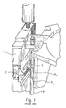
- Known fluid pump assemblies such as the one illustrated in U.S. Patent No. 6,212,997 B1, incorporate an over-center spring switch S to switch an air valve between "up” and “down” air pressure configurations.
- Fig.1 shows such a spring switch S in more detail.
- a shift arm is fixed at one end to the driving shaft and at the other end slidably fits over a push rod R, as shown in U.S. Patent No. 6,212,997 B1. Near the end of a stroke the shift arm encounters a stop on the push rod R, causing the push rod R to move.
- one of two rings R 1 and R 2 on the push rod R proximate to the air valve V is thereby caused to contact a spring switch S extension E.
- the spring switch S is thus moved between an "up” and "down” position.
- the spring force applied by the over-center spring switch S normally is quite high to achieve fast shifting. Fast shifting is desired because, as the piston changes direction, inevitably there is a short time where the piston is not moving at all. A high spring force keeps this time to a minimum, so that the fluid is pumped at as constant a rate as possible. Otherwise spurting of the fluid being pumped (or "wink") can occur, which is undesired in the application of liquid coatings to articles.
- the high spring force leads to wear of the parts, especially at the pivot points, and therefore there is a need for part replacement over time. It also can require hardened steel components, and several interconnected parts, both of which increase the cost of the system. Also, a cover is required for the push rod R and spring switch S, to protect against operators being injured by these parts during use.
- U.S. 6123008 discloses a compressed air piston engine with a driving shaft in the form of a piston rod which may be coupled to a driven shaft at its lower end.
- the present invention provides a fluid pump assembly comprising a driving reciprocating shaft operatively connected to a driving assembly and a driven reciprocating shaft operatively connected to a plunger in a fluid housing, characterised in that the driving shaft has one or more driving detents at a coupled end and the driven shaft has one or more driven detents at a coupled end, at least two inner collars, each of which comprises a driving inner projection sized and placed to fit into one or more driving detents to create a driving radial interface, and a driven inner projection sized and placed to fit into one or more driven detents to create a driven radial interface, the inner collars being placed around the driving and driven shafts at their coupled ends, and an outer collar placed around the inner collars.
- the fluid pump assembly has an improved coupling between driving and driven reciprocating shafts.
- the new coupling operates both to hold the shafts together and to align them along a common longitudinal axis. It further permits a quick connection and disconnection.
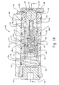
- Fig. 7A-7B is a cross-sectional view of a switch in an unactuated position.
- Fig. 7C is a cross-sectional view of a switch in an unactuated position, taken along section C-C shown in Fig. 7B, additionally showing air passageways leading from the switch.
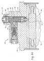
- Fig. 8A-8B is a cross-sectional view of a switch in an actuated position.
- Fig. 9 illustrates a schematic air diagram for a fluid pump system.
- a reciprocating shaft connection 10 is illustrated.
- the invention is shown and described herein with reference to a specific configuration of the reciprocating shaft connection, this description is intended to be exemplary in nature and should not be construed in a limiting sense. Those skilled in the art will readily appreciate that the present invention may be realized in many different forms and configurations.
- the present invention in one aspect is more broadly directed to the idea of providing a reciprocating shaft connection that can be easily coupled and uncoupled, and still maintain secure longitudinal alignment of the reciprocating shafts.
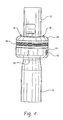
- Fig. 3 shows the basic components in the reciprocating shaft connection: a first, driving shaft 12; a second, driven shaft 14; two inner collars 16, 18; and an outer collar 20.
- the two shafts 12, 14 are shown oriented at some small angle from a pure vertical disposition, with the driving shaft 12 located above the driven shaft 14.
- the two shafts 12, 14 may be vertically disposed, horizontally disposed, or co-linearly disposed at some angle between vertical and horizontal.
- the driven shaft 14 may be located above the driving shaft 12.
- Fig. 2 shows the driving shaft 12 connected to the air motor of the present invention.
- driving shaft 12 is preferably connected to a driven shaft for a paint pump such as driven shaft 22 in U.S. Patent No. 6,212,997 B1 which is hereby incorporated by reference in its entirety.
- the driving shaft 12 is operatively connected at one end to the air motor of the present invention as noted. This air motor, later described in detail, reciprocates the driving shaft 12.
- Shaft 12 is referred to herein as the driving shaft 12 because it causes the driven shaft 14 to reciprocate.
- the driving shaft 12 is a "driven” shaft.
- the driven shaft 14 is a “driving" shaft with respect to the fluid being driven by the fluid pump assembly.
- the driving shaft 12 is coupled at a coupled end 22 to a coupled end 24 of the driven shaft 14.
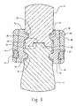
- the coupled end 22 of the driving shaft 12 has a tab aperture 26 (shown in Fig. 5), and the coupled end 24 of the driven shaft 14 has a tab 30.
- the tab aperture 26 and tab 30 may have any desired shape, such as a circle (as shown in the Figures), a square, a triangle, and the like. It is preferred that they have a circular shape.
- the tab 30 projects into the tab aperture 26. This aids in keeping the shafts 12, 14 aligned during the coupling operation.
- a gap 31 (shown in Fig. 5) is left between the top of the tab 30 and the bottom of the tab aperture 26. In that way the load is borne where the annular portions of the coupled ends 22, 24 abut around the tab aperture 26 and tab 30. To prevent wear and help maintain shaft alignment, those annular portions should be substantially flat and substantially parallel to each other.
- the tab aperture 26 and the tab 30 are designed to provide a tight fit, they will further help orient the two shafts 12, 14 along co-linear axes during reciprocation of the shafts 12, 14.
- the tab aperture 26 and tab 30 may be made circular in shape with the radius of the aperture 26 being just slightly larger than the radius of the tab 30.
- the coupled end 22 of the driving shaft 12 may include a tab 30, with the coupled end 24 of the driven shaft 14 including a tab aperture 26.
- the coupled end 22 of the driving shaft 12 is connected to the coupled end 24 of the driven shaft 14 by inner collars 16, 18 and an outer collar 20.
- the inner collars 16, 18 are placed around the two shafts 12, 14. Two or more inner collars may be used; the Figures show two inner collars 16, 18 as a preferred embodiment.
- the inner collars need not be identically sized, so that for example a first inner collar may cover 180° of the circumference of the shafts 12, 14, a second may cover 90° and a third may cover the remaining 90°.
- Identically sized collars are preferred because they reduce the number of parts which must be made and used. Additionally, the inner collars need not completely surround the circumference of the two shafts 12, 14. However, complete coverage is preferred so that the reciprocating force may be distributed over as wide an area as possible, thus minimizing wear of the various parts.
- the inner collars 16, 18 hold the shafts 12, 14 together via mating projections and detents.
- the coupled ends 22, 24 respectively have ring detents 28, 32 and the two inner collars 16, 18 each have two ring projections 34, 36. Ring projections 34 fit into ring detent 28, while ring projections 36 fit into ring detent 32.
- the coupled ends 22, 24 may have ring projections which fit into ring detents in the inner collars. Further, in place of rings which circumferentially extending in an unbroken fashion, more discrete projection / detent combinations may be used.
- each inner collar 16, 18 may include two or more circumferentially spaced-apart projections which fit into mating detents in the shafts 12, 14, sized to provide a tight fit. This would prevent relative rotation between the reciprocating shafts and the inner collar members, which may be useful for some applications.
- the outer collar 20 is moved from its momentary position (over the driving shaft 12 spaced away from the coupled end 22) to a rest position covering the two inner collars 16, 18.
- the outer collar 20 preferably has a sloping internal surface 38 corresponding to a sloping external surface 40 of the inner collars 16, 18. This creates a compressive force holding the inner collars 16, 18 against the reciprocating shafts 12, 14.
- friction created along the sloping surfaces 38, 40 may serve to prevent the outer collar 20 from slipping off of the inner collars 16, 18.
- the outer collar 20 may, however, be more forcefully secured to the inner collars 16, 18 by one or more collar fasteners.
- Collar fasteners may be useful merely for added safety or where reciprocation is especially vigorous.
- the inner collars 16, 18 fit tightly enough that any collar fastener is relied upon only to hold the outer collar 20 in place, not to transmit reciprocating force from the driving shaft 12 to the driven shaft 14.
- the collar fastener may be, for example, an elastomeric snap ring or a clip placed around the driving shaft 12 on top of the outer collar 20; or a pin may be housed in the diving shaft 12 and disposed just above the outer collar 20, or receivable in a pin hole within the outer collar 20.
- One or more set screws 42 are preferably used as a collar fastener.
- the set screws 42 may extend through threaded screw apertures 44 in the outer collar 20 (threading not shown in the Figures).
- the set screws 42 are received in a recess of the inner collars 16, 18.
- Such a recess may comprise an outer ring detent 46, as shown in the Figures, or a series of circumferentially spaced external apertures in the inner collars 16, 18 (one for each set screw 42). Interference between the set screws 42 and the ring detents 46 or external apertures in the inner collars 16, 18 prevent the outer collar 20 from slipping off the inner collars 16, 18.
- the external surface of the outer collar 20 exhibits several ridges 48. These ridges 48 permit a user to obtain a better grip in the outer collar 20, either for coupling or uncoupling the shaft connection. This can be useful, for example, because after use over a period of time the outer collar 20 tends to stick to the inner collars 16, 18.
- the ridges 48 provide a convenient place to grip with hands or to nudge with a screwdriver or other tool so that the outer collar 20 will slip off the inner collars 16, 18.
- An indicator 50 may be placed on the outer collar 20, or on one of the shafts 12, 14, to show in what direction the outer collar 20 should be moved to slip it off the inner collars 16, 18.
- shafts and collar Materials choice for the shafts and collar is, of course, dictated by the loads borne by these components. In the Applicants' intended use the shafts will be bearing about 10,000 pounds of force. At that level of force, steel may appropriately be used to make the various components. Type 303 steel may be used to help prevent environmental effects on the components. The Applicants have found Type 4140 steel sufficient for the inner collar 16, 18 members and Type 303 steel sufficient for the outer collar 20. For applications where less force is being transmitted, use of plastic may be appropriate for these components.
- this coupling creates a radial surface as an interface between the inner collars 16, 18 and the shafts 12, 14.
- the bearing surfaces of ring projections 34, 36 and ring detents 28, 32 create an arcuate interface between these elements.
- sloping interface 38, 40 serves two purposes at the same time. It both holds the coupled ends 22, 24 together and also aligns the shafts 16, 18 so that their longitudinal axes are substantially colinear.
- FIG. 2 A main valve 100 controls whether pressurized air enters the piston chamber 102 via an lower passageway 104 or an upper passageway 106.
- "up”, “down” and similar relational terms are used for convenient labels when referring to the embodiments illustrated in the Figures. It will be appreciated that, in real use, the illustrated embodiment could in effect be turned upside down if it is desired to drive the driving shaft 12 from below instead of from on top as illustrated.
- the main valve 100 operates in the following manner.
- a generally cylindrical valve shaft 114 with two reduced diameter sections 116, 118 moves up and down within the main valve 100.
- the valve shaft 114 is shown in an up position in Fig. 6.
- Pressurized air enters the main valve 100 via an inlet 120.
- Intermediate o-rings 122 seal against the outer circumference of the valve shaft 114 to direct the pressurized air either through the lower annular recess 116 and into the lower passageway 104, or through the upper annular recess 118 and into the upper passageway 106. In this way, switching of the main valve 100 proceeds by moving the valve shaft 114 up and down.
- That switching is achieved with two switches 124.
- One switch 124 is disposed at the top of the piston chamber 102, as shown in Figs. 6-8, the other at the bottom of the piston chamber 102.
- Figures 7A, 7B, 7C, 8A and 8B only illustrate the switch 124 at the top of the piston chamber 102 because it operates in the same fashion as the switch 124 at the bottom of the piston chamber 102.
- the switch comprises a vertical plunger 128 and a three-way valve 125.
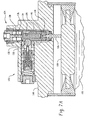
- FIG. 7A-7C illustrates the switch 124 in cross section at the moment the piston 108 first contacts the actuator pin 126.
- the actuator pin 126 is either integral with, or fixedly attached to (such as by threading), a vertical plunger 128 housed within a plunger housing 129.
- the vertical plunger 128 has a recess 130 for receiving a ball 132 of the three-way valve 125, as further discussed below.
- the vertical plunger also has an upper bore 134, fitted within which is a spring alignment rod 138 surrounded by a spring 136.
- the spring 136 biases the vertical plunger 128 in the downward direction.
- Various o-rings seal against air passage in or out of the piston chamber 12 through the switch 124.
- the upward-moving piston 102 vertically displaces the actuator pin 126 against the bias of the spring 136, actuating the switch 124.
- the plunger housing 129 preferably is generally cylindrical in shape, except that a flattened region 146 is formed in the side facing the three-way valve 125.
- the flattened region .146 aids alignment of the three-way valve 125 with respect to the plunger housing 129, including proper alignment of the ball 132 within the recess 130. It also permits removal of the plunger housing 129 from the upper wall 148 of the piston chamber 102 without first having to remove the three-way valve 125.
- Fig. 8A-8B shows the switch 124 in an actuated position.
- the ball 132 is horizontally displaced against the bias of the ball spring 144 to reach the position shown in Fig. 8A-8B.
- the lower surface 150 of the vertical plunger 128 defining the recess 130 should be angled so that it touches the outer surface of the ball 132 at all times (before, during, and after actuation). This maximizes the speed of the switch 124.
- the exact angle of the lower surface 150 is determined by the amount of horizontal ball 132 displacement required to open the three-way valve 125.
- the principal function of the recess 130 is to force horizontal displacement of the ball 132, so it is not necessary for the recess 130 to extend all the way around the vertical plunger 128 as illustrated. This annular recess is, nonetheless, preferred because it simplifies manufacture and assembly.
- the horizontal displacement of the ball 132 opens a three way valve 125.
- this actuation it is desirable for this actuation to be as fast as possible to avoid spurting of the pumped fluid.
- the external configuration of the valve housing 152 is generally cylindrical in shape with three annular recesses: an input annulus 154, a delivery annulus 156, and an exhaust annulus 158.
- An internal, cylindrical bore in the valve housing 152 holds a transfer body 159 with an end cap 161 threaded into one side (the end cap 161 may alternatively be made integral with the transfer body 159).
- the transfer body 159 is held in place against a counterbore 163 within the valve housing 152 by a holding spring 165 and a closure cap 164.
- the closure cap 164 may be held in place within the three-way valve 125 with adhesive, a threading attachment, a tight fight, or the like.
- Housed within the transfer body 159 is a transfer shaft 167 with a transfer plug 168 and an exhaust plug 182.
- Pressurized air is supplied to the input annulus 154 through input passageway 155 in the upper wall 148.
- One or more input holes 160 permit the pressurized air to pass from the input annulus 154 to an input chamber 162 within the valve housing 152, between the closure cap 164 and the transfer body 159.
- a transfer port 166 in the transfer body 159 is closed by a transfer plug 168, biased closed by a transfer spring 170.
- the pressurized air is trapped within the input chamber 162.
- the transfer port 166 leads to a delivery chamber 172 within the transfer body 159.
- One or more transfer holes 171 lead from the delivery chamber 172 to an external annulus 173 of the transfer body 159. From there one or more delivery holes 174 permit air to transfer between the delivery chamber 172 and the delivery annulus 156. Air within the delivery annulus 156 can travel to the main valve 100 via delivery passageways 157 in the upper wall 148, as further discussed below.
- air may freely communicate between the delivery chamber 172 and an exhaust chamber 176 through an exhaust port 178 in the transfer body 159.
- One or more exhaust holes 179 lead from the exhaust chamber 176 to the exhaust annulus 158, and an exhaust passageway 169 in the upper wall 148 leads from there to the atmosphere.
- the exhaust port 178 is formed as a central bore, with one or more exit holes 180 (two are shown in the Figures), within the ball pin 142.
- the exhaust port 178 may be closed by an exhaust plug 182 disposed within the delivery chamber 172, but the exhaust port 178 remains open when the three-way valve 125 is closed.
- air is free to travel between the delivery chamber 172 and the exhaust chamber 176.
- the three-way valve 125 is opened when the ball 132 is forced back by the vertical plunger 128, to the position shown in Fig. 8A-8B .
- the exit holes 180 are closed as the ball pin 142 is pushed back through an internal bore in the transfer body 159.
- the exhaust chamber 176 is sealed away from the delivery chamber 172, which is turn is still sealed away from the input chamber 160.
- the three way valve 125 operates in the following manner.
- the pressurized air supplied via the input annulus 154 is held within the input chamber 162.
- the delivery annulus 156 is open to the exhaust annulus 158. Because air passageways lead from the delivery annulus 156 to the main valve 100, with the three way valve 125 in the closed position no pressurized air is delivered to the main valve 100.
- the pressurized air supplied via input annulus 154 is free to enter the delivery annulus 156.
- the exhaust annulus 158 is sealed off from both the input annulus 154 and the delivery annulus 156.
- pressurized air is delivered to the main valve 100 in the following way. Air enters the delivery annulus 156 and flows through delivery passageway 157 into an air line 202. Air line 202 is connected (in Figure 2) to a bore 200 into the upper chamber 188 in main valve 100. As pressurized air enters chamber 188 it pushes the shaft 114 down in Figure 2 to divert the air flow into upper passageway 106 to cause air to flow into the top of chamber 102 to reverse the direction of movement of piston 108 to a downward direction in Figure 2.
- the lower three-way valve 125 will, in the same manner as has been described above with respect to the upper three-way valve 125, supply pressurized air from the lower three-way valve 125 through an air line 206 which is connected to a bore 204 in Figure 2. Bore 204 admits pressurized air into lower chamber 190 which, once again, reverses the direction of movement of shaft 114 to move it upwardly in Figure 2 and reroute the air from upper passage 106 to lower passageway 104. This reverses the direction of movement of piston 108 to move it in an upward direction in Figure 2 again, to complete the cycle.
- the driving shaft 12 is reciprocated to pump paint through the pump driven by the driven shaft 14 by a completely pneumatic air motor piston shifting system, without the need for a mechanical shifting linkage with a heavy spring.
- This all pneumatic system provides the advantages described above, namely, fewer wear parts, easier maintenance and greater operator safety.
- the switches 124 will completely prevent pressurized air being delivered to the upper chamber 188 or lower chamber 190.
- an unactuated three way valve 125 may bleed pressurized air out to the main valve 100. Then the valve shaft 114 may be caused to move only partway within the main valve 100, reaching an undesirable middle position. In that position, pressurized air supplied to the inlet 120 may be supplied to both the lower passageway 104 and the upper passageway 106. Thus pressure is equalized in the piston chamber 102, and the pump will stall. The likelihood of such a stall increases with lower piston cycle frequency.
- the valve shaft 114 may be more securely held in its upper and lower positions. For example, one may place detents in the valve shaft 114 and spring balls into the walls of the bore in the main valve 100, so that the balls are forced into the detents when the valve shaft 114 is in one of its two proper positions. Pressurized air leaking through the three way valve 125 will be at a lesser pressure than the air delivered when the switch 124 is actuated. So, the spring force behind the ball springs may be calibrated to prevent movement of the valve shaft 114 due to bled air, but permit movement when the switch 124 is activated. This, however, leads to a point of wear in the system - namely, the ball spring and detents.
- FIG. 9 illustrates a schematic air diagram for a system incorporating such a four way valve 192, which is readily available as an off-the-shelf product. Arrows indicate in what direction air flows through the various passageways, if it is flowing at all. Pressurized air is supplied from an air compressor 194 to each three way valve 125, the main valve 100 and the four way valve 192.
Landscapes
- Engineering & Computer Science (AREA)
- Mechanical Engineering (AREA)
- General Engineering & Computer Science (AREA)
- Chemical & Material Sciences (AREA)
- Analytical Chemistry (AREA)
- Physics & Mathematics (AREA)
- Fluid Mechanics (AREA)
- Reciprocating Pumps (AREA)
Claims (10)
- Fluidpumpenanordnung mit einem hin und hergehenden Antriebsschaft (12), der mit einer Antriebsanordnung verbunden ist, und einem hin und hergehenden Abtriebsschaft (14), der mit einem Kolben in einem Fluidgehäuse verbunden ist, dadurch gekennzeichnet,
dass der Antriebsschaft (12) eine oder mehrere Antriebsaussparungen (28) an einem Kopplungsende und der Abtriebsschaft (14) eine oder mehrere Abtriebsaussparungen (32) an einem Kopplungsende aufweist,
dass mindestens zwei innere Kragen (16, 18) vorgesehen sind, von denen jeder einen inneren Antriebsvorsprung (34) mit solcher Größe und Position hat, dass er in eine oder mehrere der Antriebsaussparungen (28) passt, um eine radiale Antriebsfläche zu bilden, und einen inneren Abtriebsvorsprung (36) mit solcher Größe und Position hat, dass er in eine oder mehrere der Abtriebsaussparungen (32) passt, um eine radiale Abtriebsfläche zu bilden,
dass die inneren Kragen (16, 18) um die Antriebs- und Abtriebsschäfte (12,14) herum im Bereich der Kopplungsenden angeordnet sind und dass ein äußerer Kragen (20) um die inneren Kragen (16, 18) herum angeordnet ist. - Fluidpumpenanordnung nach Anspruch 1, dadurch gekennzeichnet, dass die Antriebsanordnung eine luftgetriebene Kolbenanordnung enthält.
- Fluidpumpenanordnung nach Anspruch 2, weiter gekennzeichnet durch eine Fluidleitung, die von der Fluidpumpenanordnung zu einer Spritzpistole zum Spritzen des durch die Fluidpumpenanordnung gepumpten Fluids führt.
- Fluidpumpenanordnung nach einem oder mehreren der vorstehenden Ansprüche, weiter gekennzeichnet durch eine auf einer externen Fläche des äußeren Kragens (20) angeordnete Rippe (48).
- Fluidpumpenanordnung nach Anspruch 4, weiter gekennzeichnet durch ein auf einer externen Fläche des äußeren Kragens (20) angeordnetes Anzeigeelement (50) zum Anzeigen, wie der äußere Kragen (20) von den inneren Kragen (16, 18) entfernt werden kann.
- Fluidpumpenanordnung nach einem oder mehreren der vorstehenden Ansprüche, weiter gekennzeichnet durch mindestens eine Bohrung (44) im äußeren Kragen (20) und eine in die Bohrung einzusetzende Stellschraube.
- Fluidpumpenanordnung nach Anspruch 6, dadurch gekennzeichnet, dass im äußeren Kragen (20) zwei Bohrungen (44) vorgesehen sind und dass die inneren Kragen (16, 18) Aussparungen (46) zur Aufnahme der Stellschrauben (42) aufweisen.
- Fluidpumpenanordnung nach einem oder mehreren der vorstehenden Ansprüche, dadurch gekennzeichnet, dass die inneren Kragen (16, 18) mit einer geneigten Außenfläche (40) und der äußere Kragen (20) mit einer geneigten Innenfläche (38) versehen sind und dass die geneigte Außenfläche (40) an der geneigten Innenfläche anliegt, wenn die beiden Schäfte (12, 14) miteinander verbunden sind.
- Fluidpumpenanordnung nach einem oder mehreren der vorstehenden Ansprüche, dadurch gekennzeichnet, dass die eine oder die mehreren Antriebs- und Abtriebsausparungen jede eine Ringaussparung (28, 32) und die inneren Antriebs- und Abtriebsvorsprünge jeder einen Ringvorsprung (34, 36) enthalten.
- Fluidpumpenanordnung nach einem oder mehreren der vorstehenden Ansprüche, dadurch gekennzeichnet, dass an dem Koppelende des hin und hergehenden Antriebsschaftes (12) eine erste im wesentlichen flache Fläche und an dem Koppelende des hin und hergehenden Abtriebsschaftes (14) eine zweite im wesentlichen flache Fläche vorgesehen ist und dass die erste und die zweite flache Fläche im wesentlichen parallel zueinander liegen, wenn die Antriebs- und Abtriebsschäfte miteinander gekuppelt sind.
Applications Claiming Priority (5)
| Application Number | Priority Date | Filing Date | Title |
|---|---|---|---|
| US32739401P | 2001-10-05 | 2001-10-05 | |
| US32753401P | 2001-10-05 | 2001-10-05 | |
| US327394P | 2001-10-05 | ||
| US327534P | 2001-10-05 | ||
| PCT/US2002/032011 WO2003031819A2 (en) | 2001-10-05 | 2002-10-05 | Shaft coupling and shifting mechanism for pneumatic pump drive |
Publications (2)
| Publication Number | Publication Date |
|---|---|
| EP1432913A2 EP1432913A2 (de) | 2004-06-30 |
| EP1432913B1 true EP1432913B1 (de) | 2006-06-28 |
Family
ID=36423507
Family Applications (1)
| Application Number | Title | Priority Date | Filing Date |
|---|---|---|---|
| EP02800940A Expired - Lifetime EP1432913B1 (de) | 2001-10-05 | 2002-10-05 | Wellenkupplung und schiebemechanismus für druckluftpumpe |
Country Status (4)
| Country | Link |
|---|---|
| US (1) | US6951163B1 (de) |
| EP (1) | EP1432913B1 (de) |
| AU (1) | AU2002334890A1 (de) |
| DE (1) | DE60212863T2 (de) |
Families Citing this family (6)
| Publication number | Priority date | Publication date | Assignee | Title |
|---|---|---|---|---|
| US20090279946A1 (en) * | 2008-05-09 | 2009-11-12 | Honeywell International Inc. | Shaft coupling device |
| US8177524B1 (en) * | 2008-08-19 | 2012-05-15 | Wagner Spray Tech Corporation | Manual locking clamp for piston paint pump |
| CN101799000B (zh) * | 2010-03-15 | 2011-09-21 | 浙江大学 | 利用螺杆换向的气动泵 |
| JP2016156405A (ja) * | 2015-02-23 | 2016-09-01 | アネスト岩田株式会社 | パイロットバルブ |
| US12188460B2 (en) | 2021-02-05 | 2025-01-07 | Wagner Spray Tech Corporation | Piston coupler for a reciprocating pump |
| CN113540798B (zh) * | 2021-07-14 | 2023-09-26 | 京信通信技术(广州)有限公司 | 多频天线、调频控制机构及装置 |
Family Cites Families (23)
| Publication number | Priority date | Publication date | Assignee | Title |
|---|---|---|---|---|
| US612008A (en) * | 1898-10-11 | Shampoo head-rest | ||
| US2789540A (en) * | 1955-12-02 | 1957-04-23 | Mckiernan Terry Corp | Compound hammer |
| DE1264956B (de) | 1962-11-21 | 1968-03-28 | Torkret G M B H | Kolbenpumpe mit hydraulischem Antrieb fuer die Foerderung von Beton u. dgl. |
| US3282167A (en) | 1964-04-09 | 1966-11-01 | Walker Mfg Co | Reciprocating fluid motor |
| US3424092A (en) | 1966-10-28 | 1969-01-28 | Smith Corp A O | Paint pumping system |
| DE1948247A1 (de) | 1969-09-24 | 1971-04-29 | Internat Lead Zinc Res Organiz | Verfahren zum Herstellen von Hexaaryl-Dibleiverbindungen |
| DE2626954C2 (de) * | 1976-06-16 | 1985-04-11 | Schmidt, Kranz & Co Gmbh, Zweigniederlassung Maschinenbau, 3421 Zorge | Steuerschieberanordnung für eine durch Druckluft angetriebene Hydraulikpumpe |
| US4160626A (en) | 1977-09-19 | 1979-07-10 | Vapor Corporation | Drive rod coupling for positive displacement pump |
| US4176676A (en) * | 1978-01-03 | 1979-12-04 | Townsend Loren R | Means for converting a water drive center pivot irrigation system to air drive |
| US4159132A (en) | 1978-04-03 | 1979-06-26 | Hitz Gifford L | Sealed connection |
| US4719845A (en) | 1985-12-05 | 1988-01-19 | Adolph Coors Company | Joint system |
| IT1223054B (it) | 1987-11-04 | 1990-09-12 | O D L Srl | Pompa per il trasferimento di liquidi in particolare di birra o di bevande gasate |
| US4846045A (en) * | 1987-12-07 | 1989-07-11 | Mcneil (Ohio) Corporation | Expansible chamber motor |
| DE69126136T2 (de) | 1990-07-09 | 1997-12-11 | Deco-Grand, Inc., Royal Oak, Mich. | Wasserpumpe |
| US5482432A (en) | 1990-07-09 | 1996-01-09 | Deco-Grand, Inc. | Bearingless automotive coolant pump with in-line drive |
| US5131632A (en) | 1991-10-28 | 1992-07-21 | Olson Darwin B | Quick coupling pipe connecting structure with body-tapered sleeve |
| US5366353A (en) * | 1994-04-13 | 1994-11-22 | Hand Kent P | Air valve with bleed feature to inhibit icing |
| FR2721461B1 (fr) * | 1994-06-16 | 1996-09-06 | France Telecom | Signal formé d'une pluralité de fréquences porteuses orthogonales organisé de façon à simplifier la réception d'un des signaux source le composant, procédé d'émission et récepteur correspondants. |
| DE29710807U1 (de) | 1997-06-19 | 1997-08-28 | WiWa Wilhelm Wagner GmbH & Co KG, 35633 Lahnau | Druckluft-Kolbenmotor |
| US6095772A (en) | 1998-04-20 | 2000-08-01 | The Gorman-Rupp Company | Shaft coupling system |
| US6164188A (en) | 1998-11-23 | 2000-12-26 | Miser; H T | Reciprocating pump/compressor with self-aligning piston |
| DE19860466C1 (de) | 1998-12-28 | 2000-06-29 | Schmidt & Co Gmbh Kranz | Pneumatisch angetriebene Hydraulikpumpe |
| US6212997B1 (en) | 1999-02-01 | 2001-04-10 | Nordson Corporation | Reciprocating fluid pumps with chromium nitride coated components in contact with non-metallic packing and gasket materials for increased seal life |
-
2002
- 2002-05-10 US US10/491,556 patent/US6951163B1/en not_active Expired - Fee Related
- 2002-10-05 DE DE60212863T patent/DE60212863T2/de not_active Expired - Fee Related
- 2002-10-05 AU AU2002334890A patent/AU2002334890A1/en not_active Abandoned
- 2002-10-05 EP EP02800940A patent/EP1432913B1/de not_active Expired - Lifetime
Also Published As
| Publication number | Publication date |
|---|---|
| US6951163B1 (en) | 2005-10-04 |
| DE60212863T2 (de) | 2006-11-16 |
| EP1432913A2 (de) | 2004-06-30 |
| AU2002334890A1 (en) | 2003-04-22 |
| DE60212863D1 (de) | 2006-08-10 |
| US20050199119A1 (en) | 2005-09-15 |
Similar Documents
| Publication | Publication Date | Title |
|---|---|---|
| US6868774B2 (en) | Shaft coupling and shifting mechanism for pneumatic pump | |
| US5564911A (en) | Pump, control valve and diaphragm | |
| US6514058B1 (en) | Compressor having an improved valved piston device | |
| KR101582911B1 (ko) | 자기 멈춤쇠를 갖는 밸브를 포함하는 공압 모터 | |
| US8966760B2 (en) | Method of manufacturing a positive displacement injection pump | |
| EP0711905B1 (de) | Verbessertes mechanisch gesteuertes pneumatisches Servoventil | |
| KR20090128466A (ko) | 자기적으로 시퀀스된 공압 모터 | |
| EP1432913B1 (de) | Wellenkupplung und schiebemechanismus für druckluftpumpe | |
| EP0400846A2 (de) | Ventil für Flüssigkeiten | |
| KR20090128467A (ko) | 공압식 자체-조절 밸브 | |
| AU2002300673B2 (en) | Delay-interruption connector for pneumatic tool | |
| CN101858438A (zh) | 具有可替换致动器的配给器及相关方法 | |
| EP0903523A1 (de) | Durchflussregler | |
| US3489100A (en) | Air driven fluid pump | |
| EP1437508B1 (de) | Integriertes Ringventil für einen Kompressorkolben | |
| US5002469A (en) | Switching device for reciprocating pumps | |
| US6089532A (en) | Valve for use with agricultural sprayers | |
| AU2015335631C1 (en) | Air motor | |
| EP0321573B1 (de) | Hin- und herbewegende schaltungsstrukttur für pumpe | |
| US4827832A (en) | Valve system for a reciprocating device | |
| US5074767A (en) | Positive displacement pump with rotating reciprocating piston and improved lubrication feature | |
| US4879943A (en) | Expansible chamber motor with snap-acting valve | |
| EP0186606B1 (de) | Flüssigkeitsbetätigungseinrichtung | |
| US5120202A (en) | Switching device for reciprocating pumps | |
| EP0775278B1 (de) | Membranventil |
Legal Events
| Date | Code | Title | Description |
|---|---|---|---|
| PUAI | Public reference made under article 153(3) epc to a published international application that has entered the european phase |
Free format text: ORIGINAL CODE: 0009012 |
|
| 17P | Request for examination filed |
Effective date: 20040329 |
|
| AK | Designated contracting states |
Kind code of ref document: A2 Designated state(s): AT BE BG CH CY CZ DE DK EE ES FI FR GB GR IE IT LI LU MC NL PT SE SK TR |
|
| AX | Request for extension of the european patent |
Extension state: AL LT LV MK RO SI |
|
| 17Q | First examination report despatched |
Effective date: 20050517 |
|
| GRAP | Despatch of communication of intention to grant a patent |
Free format text: ORIGINAL CODE: EPIDOSNIGR1 |
|
| GRAS | Grant fee paid |
Free format text: ORIGINAL CODE: EPIDOSNIGR3 |
|
| GRAA | (expected) grant |
Free format text: ORIGINAL CODE: 0009210 |
|
| AK | Designated contracting states |
Kind code of ref document: B1 Designated state(s): DE FR |
|
| REF | Corresponds to: |
Ref document number: 60212863 Country of ref document: DE Date of ref document: 20060810 Kind code of ref document: P |
|
| PGFP | Annual fee paid to national office [announced via postgrant information from national office to epo] |
Ref country code: DE Payment date: 20061023 Year of fee payment: 5 |
|
| ET | Fr: translation filed | ||
| PLBE | No opposition filed within time limit |
Free format text: ORIGINAL CODE: 0009261 |
|
| STAA | Information on the status of an ep patent application or granted ep patent |
Free format text: STATUS: NO OPPOSITION FILED WITHIN TIME LIMIT |
|
| 26N | No opposition filed |
Effective date: 20070329 |
|
| PG25 | Lapsed in a contracting state [announced via postgrant information from national office to epo] |
Ref country code: DE Free format text: LAPSE BECAUSE OF NON-PAYMENT OF DUE FEES Effective date: 20080501 |
|
| REG | Reference to a national code |
Ref country code: FR Ref legal event code: ST Effective date: 20080630 |
|
| PGFP | Annual fee paid to national office [announced via postgrant information from national office to epo] |
Ref country code: FR Payment date: 20061016 Year of fee payment: 5 |
|
| PG25 | Lapsed in a contracting state [announced via postgrant information from national office to epo] |
Ref country code: FR Free format text: LAPSE BECAUSE OF NON-PAYMENT OF DUE FEES Effective date: 20071031 |