EP1432275A1 - Überwachungsvorrichtung - Google Patents
Überwachungsvorrichtung Download PDFInfo
- Publication number
- EP1432275A1 EP1432275A1 EP02360352A EP02360352A EP1432275A1 EP 1432275 A1 EP1432275 A1 EP 1432275A1 EP 02360352 A EP02360352 A EP 02360352A EP 02360352 A EP02360352 A EP 02360352A EP 1432275 A1 EP1432275 A1 EP 1432275A1
- Authority
- EP
- European Patent Office
- Prior art keywords
- wire
- isdn
- channel
- monitoring device
- connection
- Prior art date
- Legal status (The legal status is an assumption and is not a legal conclusion. Google has not performed a legal analysis and makes no representation as to the accuracy of the status listed.)
- Granted
Links
- 238000012806 monitoring device Methods 0.000 claims abstract description 83
- 238000012544 monitoring process Methods 0.000 claims abstract description 49
- 230000011664 signaling Effects 0.000 claims description 18
- 238000004891 communication Methods 0.000 claims description 12
- 238000001514 detection method Methods 0.000 claims description 6
- 238000000034 method Methods 0.000 claims description 4
- 230000000007 visual effect Effects 0.000 abstract description 3
- 230000005540 biological transmission Effects 0.000 description 15
- 230000006870 function Effects 0.000 description 6
- 230000015654 memory Effects 0.000 description 6
- 238000011156 evaluation Methods 0.000 description 4
- 238000012546 transfer Methods 0.000 description 4
- 238000002955 isolation Methods 0.000 description 3
- 238000006243 chemical reaction Methods 0.000 description 2
- 238000012545 processing Methods 0.000 description 2
- 238000012360 testing method Methods 0.000 description 2
- 101000633786 Homo sapiens SLAM family member 6 Proteins 0.000 description 1
- 102100029197 SLAM family member 6 Human genes 0.000 description 1
- 230000004913 activation Effects 0.000 description 1
- 238000004590 computer program Methods 0.000 description 1
- 230000001066 destructive effect Effects 0.000 description 1
- 230000000694 effects Effects 0.000 description 1
- 238000005259 measurement Methods 0.000 description 1
- 238000011084 recovery Methods 0.000 description 1
- 230000004044 response Effects 0.000 description 1
- 238000000926 separation method Methods 0.000 description 1
- 230000001960 triggered effect Effects 0.000 description 1
Images

Classifications
-
- H—ELECTRICITY
- H04—ELECTRIC COMMUNICATION TECHNIQUE
- H04L—TRANSMISSION OF DIGITAL INFORMATION, e.g. TELEGRAPHIC COMMUNICATION
- H04L63/00—Network architectures or network communication protocols for network security
-
- H—ELECTRICITY
- H04—ELECTRIC COMMUNICATION TECHNIQUE
- H04L—TRANSMISSION OF DIGITAL INFORMATION, e.g. TELEGRAPHIC COMMUNICATION
- H04L63/00—Network architectures or network communication protocols for network security
- H04L63/30—Network architectures or network communication protocols for network security for supporting lawful interception, monitoring or retaining of communications or communication related information
-
- H—ELECTRICITY
- H04—ELECTRIC COMMUNICATION TECHNIQUE
- H04M—TELEPHONIC COMMUNICATION
- H04M3/00—Automatic or semi-automatic exchanges
- H04M3/22—Arrangements for supervision, monitoring or testing
- H04M3/2281—Call monitoring, e.g. for law enforcement purposes; Call tracing; Detection or prevention of malicious calls
-
- H—ELECTRICITY
- H04—ELECTRIC COMMUNICATION TECHNIQUE
- H04Q—SELECTING
- H04Q11/00—Selecting arrangements for multiplex systems
- H04Q11/04—Selecting arrangements for multiplex systems for time-division multiplexing
- H04Q11/0428—Integrated services digital network, i.e. systems for transmission of different types of digitised signals, e.g. speech, data, telecentral, television signals
- H04Q11/0435—Details
- H04Q11/045—Selection or connection testing arrangements
-
- H—ELECTRICITY
- H04—ELECTRIC COMMUNICATION TECHNIQUE
- H04Q—SELECTING
- H04Q2213/00—Indexing scheme relating to selecting arrangements in general and for multiplex systems
- H04Q2213/13034—A/D conversion, code compression/expansion
-
- H—ELECTRICITY
- H04—ELECTRIC COMMUNICATION TECHNIQUE
- H04Q—SELECTING
- H04Q2213/00—Indexing scheme relating to selecting arrangements in general and for multiplex systems
- H04Q2213/13039—Asymmetrical two-way transmission, e.g. ADSL, HDSL
-
- H—ELECTRICITY
- H04—ELECTRIC COMMUNICATION TECHNIQUE
- H04Q—SELECTING
- H04Q2213/00—Indexing scheme relating to selecting arrangements in general and for multiplex systems
- H04Q2213/13095—PIN / Access code, authentication
-
- H—ELECTRICITY
- H04—ELECTRIC COMMUNICATION TECHNIQUE
- H04Q—SELECTING
- H04Q2213/00—Indexing scheme relating to selecting arrangements in general and for multiplex systems
- H04Q2213/13103—Memory
-
- H—ELECTRICITY
- H04—ELECTRIC COMMUNICATION TECHNIQUE
- H04Q—SELECTING
- H04Q2213/00—Indexing scheme relating to selecting arrangements in general and for multiplex systems
- H04Q2213/13106—Microprocessor, CPU
-
- H—ELECTRICITY
- H04—ELECTRIC COMMUNICATION TECHNIQUE
- H04Q—SELECTING
- H04Q2213/00—Indexing scheme relating to selecting arrangements in general and for multiplex systems
- H04Q2213/1316—Service observation, testing
-
- H—ELECTRICITY
- H04—ELECTRIC COMMUNICATION TECHNIQUE
- H04Q—SELECTING
- H04Q2213/00—Indexing scheme relating to selecting arrangements in general and for multiplex systems
- H04Q2213/13176—Common channel signaling, CCS7
-
- H—ELECTRICITY
- H04—ELECTRIC COMMUNICATION TECHNIQUE
- H04Q—SELECTING
- H04Q2213/00—Indexing scheme relating to selecting arrangements in general and for multiplex systems
- H04Q2213/13204—Protocols
-
- H—ELECTRICITY
- H04—ELECTRIC COMMUNICATION TECHNIQUE
- H04Q—SELECTING
- H04Q2213/00—Indexing scheme relating to selecting arrangements in general and for multiplex systems
- H04Q2213/13206—User-to-user signaling, UUS
-
- H—ELECTRICITY
- H04—ELECTRIC COMMUNICATION TECHNIQUE
- H04Q—SELECTING
- H04Q2213/00—Indexing scheme relating to selecting arrangements in general and for multiplex systems
- H04Q2213/13209—ISDN
-
- H—ELECTRICITY
- H04—ELECTRIC COMMUNICATION TECHNIQUE
- H04Q—SELECTING
- H04Q2213/00—Indexing scheme relating to selecting arrangements in general and for multiplex systems
- H04Q2213/13372—Intercepting operator
Definitions
- the invention relates to a monitoring device.
- ISDN Integrated Services Digital Network. This is because both a 4-wire to 2-wire connection for both the subscriber and the exchange Implementation takes place, which does not result in a 2-wire line assignable sequence of digital signals occurs.
- the exchange as such is the data transmitted by the Reverse implementation available again, but access to Switching center reserved for the network operator and thus without it Consent is not readily possible.
- the monitoring device generates two internal, fictitious 4-wire connection from which signals can be tapped a multiplexer / demultiplexer serve as input and control signals for the purpose of separating useful and / or signaling information.
- On Clock signals are provided to a first of the 4 wires on a second frame signals.
- On the third wire are the information signals the execution and on the fourth wire the information signals of the Reverse direction separated.
- the information signals include Both the useful information that is transmitted in so-called B channels as well as the signaling information in so-called D channels be transmitted.
- the monitoring device is in the connection to be monitored looped. This is done e.g. at the cable distributor or in the basement of one House or at any other accessible point along the Link. Monitoring is done online without negative Effects on the participant.
- DSL Digital Subscriber Line.
- the monitoring options are diverse.
- a D channel separated and using a D-channel protocol analyzer Monitoring of the separated D channel a D channel with changed Content provided when a predetermined identifier is detected.
- the monitoring device includes e.g. a microphone that provides acoustic room surveillance allows, and / or a camera that provides visual room surveillance allows.
- the identifier is advantageously a password transmitted in the D channel or a predefined phone number transmitted in the D channel certain calling subscriber.
- the D-channel protocol analyzer known password is called by a particular one Participants via a switching center to the monitoring device transfer.
- the transmission takes place e.g. im for the transmission of user-to-user Information reserved time slot in the D channel.
- the D-channel protocol analyzer monitors this time slot and compares it with that given password. He receives this from the calling subscriber transmitted password, it changes the content of the D channel Monitoring device installed at the participant to be monitored can be called.
- the D-channel protocol analyzer monitors the information transmitted in the D channel about the Number of the calling subscriber. Corresponds to the received one Number of the number of the specific, the D-channel protocol analyzer known subscriber, he changes the content of the D channel so that the installed at the monitored participant Monitoring device can be called.
- the D-channel protocol analyzer designed in such a way in the case of detection of the specified identifier the device type number contained in the separated D-channel to be replaced by a specified device type number.
- ISDN are in the D channel in addition to the number of the calling subscriber transfer the device type number of the calling subscriber.
- the Device type number indicates the device type.
- a device type is e.g. an ISDN telephone, another a fax machine.
- Using the device type number ensures that a connection between two identical devices is built, at least those with the same functionality. So it will usually an ISDN connection from an ISDN telephone of the calling party Subscriber only to an ISDN telephone of the called subscriber forwarded, and not for example to the fax machine of the called party Participant. It can also connect to a terminal adapter to which an analog telephone is connected to a Telephone call between ISDN telephone and analog telephone too enable.
- one subscriber can a maximum of eight device types can be assigned. As a rule, however used a maximum of four, e.g. for ISDN telephones, fax machines, terminal adapters, Personal computer, so that at least four are still unused.
- the An unused device type number is assigned to the monitoring device. If the monitoring device is called, none of the previously used devices activated; the called subscriber thus has no knowledge that the monitoring device has been activated. There the subscriber to be monitored is called by the calling party no telephone charges for the subscriber to be monitored, so that too monitoring participants not afterwards by the Billing with individual evidence can determine whether and in what period of time there was monitoring.
- the D-channel protocol analyzer is advantageously designed in such a way that, if the specified identifier is detected, the communication to a called and monitored subscriber is limited to layer 1 and layer 2 communication and to prevent layer 3 communication.
- a personal computer connected to the S 0 bus of the ISDN subscriber to be monitored can be used to monitor whether a B channel is occupied or not. In this respect, it could be determined whether a monitoring device was installed and activated. The occupancy of the B channel can only be determined with layer 3 communication. If this is prevented by the D-channel protocol analyzer, the monitoring device can still be activated, but the assignment of the associated B-channel is not possible.
- the D-channel protocol analyzer is advantageously designed in such a way that If the specified identifier is detected, the content of the D channel only to be changed and to the monitored participant forward if both for the monitoring participant to Available B channels are not occupied. The one to be monitored If possible, the participant should have no knowledge that he is monitored. Would monitor the two B channels of the ISDN subscriber line blocked in such a way that no more calls to Participants could be put through, e.g. because of a Busy signal, or that the participant himself no longer has any conversations could initiate, the monitoring could be detected.
- the participant has two B channels available for transmission.
- For the monitoring requires at least one B channel.
- the supervision is only started after it has been determined that both B channels are not are occupied.
- a B channel is used for monitoring and the other B channel is free for incoming and outgoing calls.
- the associated method for monitoring a ISDN subscriber builds a specific calling subscriber Connection to one between the exchange and the one to be monitored Participant switched on monitoring device.
- the Monitoring device detects the by monitoring the D channel calling subscriber based on a predetermined identifier and transmits a feedback to the exchange regarding a successful Establishing a connection to the participant to be monitored. Further transmits the monitoring device via the D channel to monitoring participants changed signaling information for the purpose of establishing a connection to one to be monitored Participant arranged monitoring device.
- D channel Protocol analyzers e.g. a D-channel monitoring can be carried out to detect the subscriber number. Furthermore, one Bit error measurement possible. There are also listening options for voice and / or Data signals created. The police have the opportunity Intercept ISDN calls. Internet traffic can also be a Participant to be monitored. Furthermore, the data traffic, e.g. Email traffic, monitored.
- the Monitoring device also for sending information in the B channel suitable. Then there is communication between Monitoring device and subscriber and switching center possible. For example, a test signal is sent that from the Switch is received and its reception quality measured becomes.
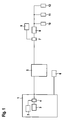
- FIG. 1 shows a monitoring device 5 in a DSL-ISDN connection.
- the monitoring device 5 is looped into a DSL-ISDN connection between an ISDN LT 3, a DSL LT 2 and a filter 4 on the network operator side and an ISDN NT 9, a DSL modem 8 and a filter 7 on the subscriber side;
- LT Line Termination
- NT Network Termination.
- the DSL with ISDN is a private telecommunications network of a network operator.
- ISDN LT 3, DSL LT 2 and filter 4 are arranged in a switching center 1.
- a network termination for ISDN is arranged at the interface to a subscriber's private network.
- the ISDN NT 9 is connected to a monitoring device and at least one terminal 11, 12 via a 4-wire S 0 bus.
- the monitoring device 10 is used to monitor the subscriber. For example, it contains a microphone and / or a camera.
- the monitoring device 10 is assigned a device type number which is not assigned to any other terminal device 11, 12 connected to the S 0 bus. If two or more monitoring devices are installed at a subscriber, different or the same device type numbers can be assigned to them. If different device type numbers are assigned, the individual monitoring devices can be addressed individually. If the same device type numbers are assigned, a sequential response takes place using, for example, a time-division multiplex protocol.
- Terminal 11 is e.g. a digital device. Serves as an analog terminal for example an analog telephone or an analog fax machine, as digital terminal, for example a computer, an ISDN telephone or a digital phone.
- Terminal 12 is e.g. a digital device. Serves as an analog terminal for example an analog telephone or an analog fax machine, as digital terminal, for example a computer, an ISDN telephone or a digital phone.
- Analogue terminals can each be connected to the S 0 bus via a so-called terminal adapter, which carries out a protocol conversion.
- analog terminals can also be connected to the S 0 bus via a private branch exchange.
- a private branch exchange can also be used to connect digital and analog devices.
- the ISDN NT 9 is on the network side via a 2-wire line with an ISDN LT 3 connected, possibly with the interposition of one or more Components, e.g. a concentrator, a splitter, etc.
- the DSL modem 8 is provided on the subscriber side the subscriber side e.g. a computer or a television is connected, e.g. for the use of service on demand and / or internet services.
- the DSL modem 8 with a DSL is on the network side LT 2 connected, possibly with the interposition of one or more Components, e.g. a concentrator, a splitter, etc.
- filters 4 and 7 are provided, each have the same structure and usually a high-pass filter Isolation of the DSL signals and a low pass filter to isolate the ISDN signals exhibit.
- Participant 6 includes a telecommunication device communication towards the participant to be monitored can be set up, for example a terminal with an ISDN terminal or a cell phone. It serves together with the Monitoring device 5 to the exchange 1 a connection to simulate the participant to be monitored in order to Monitoring device 5 to enable a connection to Build monitoring device 10, perform the monitoring and to prevent switch 1 from connecting to layer 1 disabled.
- the U K0 subscriber route is switched to permanently active, the use of subscriber 6 is not necessary. It is not necessary to detect an identifier before starting the monitoring.
- the monitoring device 5 is then able to independently determine the start time of the monitoring. If monitoring is to take place, the D channel is first monitored in the forward and backward direction. If no B channel is occupied, monitoring can take place via the monitoring device 10.
- the D-channel protocol analyzer 21 generates signaling information for establishing a connection to the subscriber to be monitored, and in particular to the monitoring device 10.
- the signaling information includes, for example, the specified device type number of the monitoring device 10.
- a decoder for example decoder 22
- FIG. 2 shows a detailed structure of the Monitoring device 5 from FIG. 1.
- the monitoring device 5 contains two inputs / outputs I / O1, I / O2 for connecting the monitoring device to an external 2-wire DSL-ISDN connection via so-called U interfaces.
- the one entrance-exit I / O1 is with ISDN LT 3 and the other input / output I / O2 is with ISDN NT 9 connected.
- the converters 15, 17 are connected to generate two internal 4-wire ISDN connections.
- the converters 15, 17 each contain a U K0 - and an IOM circuit, which are connected to one another.
- the circuits are designed as integrated circuits.
- the U K0 circuit is used to provide the 2-wire interface
- the IOM circuit is used to provide the 4-wire interface.
- Each circuit carries out a protocol conversion and also contains a device for clock recovery in order to extract the various clocks from the signal stream.
- the ISDN information is transmitted in coded form via the U K0 interface.
- Line codes are used for this, e.g. for adapting the digital data stream to the transmission medium, the transmission of the bit clock information, the transmission of the frame clock information (all ISDN connection lines use a time division multiplex system to operate the different transmission channels in one direction) and for an error detection on layer 1.
- the line codes used in ISDN can be divided into pseudo-ternary codes (AMI code, HDB-3 code), ternary codes (4B / 3T codes, here MMS43), quaternary codes (2B / 1Q codes) ,
- the line codes used in ISDN must be designed so that they are DC-free. This is the only way to separate data signals from the supply voltage, to safely separate signals at low level differences, to protect sensitive transmitters and receivers by galvanic isolation from destructive influences via the connecting cable, and to permanently encode clock information into the data stream.
- Clock signals are provided on a first of the 4 wires, on a second frame signals.
- the information signals On the third wire are the information signals the execution and on the fourth wire the information signals of the Reverse direction isolated.
- the Isolate information signals By means of the clock and frame signals, the Isolate information signals.
- the information signals include both the useful information that is transmitted in so-called B channels as well the signaling information that is transmitted in so-called D-channels become.
- a multiplexer / demultiplexer 20 which has four inputs and two outputs to connect to the two 4-wire ISDN connection has and to provide at least one channel to be monitored serves.
- the multiplexer / demultiplexer 20 is in by means of the clock and frame signals able to isolate information signals.
- the clock signals include e.g. the bit clock, which is a clock with which individual steps (mostly bits) are scanned become.
- the multiplexer / demultiplexer 20 isolates at least one monitoring transmission channel, e.g. a D channel over which Signaling signals are transmitted and / or a B channel, via the useful information is transmitted.
- the number and the selection the transmission channels to be isolated depend e.g. from the objective of surveillance. Should e.g. only the number of the called party are determined, it is sufficient to use the corresponding signaling channel (D channel) to isolate and monitor.
- Hear conversations If at least two B channels are monitored, one B channel in Execution and the associated channel in the reverse direction. In a preferred variant, all channels are always isolated, e.g. two B channels and a D-channel in the execution as well as two B-channels and a D-channel in Direction and possibly also one or more clock signals. The clock signals can then be used for clocking in subsequent processing units become.
- the number of inputs and outputs of the multiplexer / demultiplexer 20 is to choose according to the purpose.
- One or more inputs and / or Outputs can be used as external connections from the Monitoring device 5 be led out.
- the control of the Multiplexers / demultiplexers 20 are e.g. over a processor, e.g. one appropriately programmed microprocessor or digital Signal processor.
- a certain calling subscriber 6 establishes a connection to between the exchange 1 and the subscriber to be monitored switched monitoring device 5.
- the monitoring device 5 detects the calling subscriber 6 by monitoring the D channel based on a given identifier and transmits to the exchange 1 a feedback regarding a successful connection establishment to the participant to be monitored.
- the feedback serves one simulate successful connection to prevent the Switch 1 switches off the connection.
- Monitoring device 5 has its own connection to monitoring participants, of which neither the participant nor the Agency acquires knowledge. This is done by transferring changed signaling information via the D channel to monitoring participants to establish a connection to the at monitoring participants arranged monitoring device 10.
- Die Signaling information contains e.g. a device type number that is specifically assigned to the monitoring device 10.
- the Monitoring device 10 is activated and then sends Information via a B channel to the monitoring device 5.
- the Information is stored in the monitoring device 5 cached, e.g. recording on tape, and / or evaluated. If the information contains image signals, they can be viewed on a monitor be monitored by one person. Contain the information Speech signals can be transmitted through a loudspeaker by a person be monitored.
- the information via a B channel from the monitoring device 5 via the Switch 1 are forwarded to calling party 6.
- the calling subscriber 6 can then also the information buffer and / or evaluate.
- the D channel is monitored.
- the supervision e.g. in the monitoring device 5 Connection establishment request at the participant to be monitored or off, the monitoring device 5 switches the Monitoring connection via two disconnect signals.
- the one Disconnect signal is transmitted to exchange 1, the other to Monitoring device 10.
- monitoring takes place in the Monitoring device 10.
- monitoring device 10 monitoring of a normal connection is monitored.
- monitoring of a normal connection e.g. through a connection establishment request triggered by one of the terminals 11, 12 or by a Connection establishment request to one of the terminals 11, 12 a calling subscriber.
- two high-pass / low-pass filters 13, 19 are provided, which between the two inputs / outputs I / O1, I / O2 and the two converters 15, 17 are switched to a bypass connection for DSL signals to generate.
- ISDN signals are usually used at lower frequencies transmitted as DSL signals. The transmission bands of both signals do not overlap.
- Using a low-pass filter with a cut-off frequency the ISDN signals can be isolated between the transmission bands become. Thus only ISDN signals reach the converters 15, 17 no DSL signals.
- decoders 22, 23, 24, 25 or filters are optionally provided, to decode the payload.
- the payload will be coded transmission.
- the decoders 22, 23, 24, 25 are for example 4B / 3T decoder or 2B / 1 Q decoder according to the coding used.
- useful information can be tapped, e.g. monitored, processed, can be sent and / or saved.
- To the Useful information counts e.g. Voice signals, data signals, Internet signals, etc. Monitoring, etc. takes place e.g. using a special programmed processor and a memory.
- the processor is e.g. on Digital signal processor or a microprocessor used.
- processors can also have multiple processors and instead of one memory multiple memories can also be used.
- FPGA Freely Programmable gate array.
- signals e.g. Voice and Data signals
- processing units can be used become.
- the invention is independent of a special hardware and / or Software design.
- the outputs of the decoders 22, 23 are inputs of a first one Adder 26 connected, the output of which is connected to an internal or external Evaluation unit, e.g. a personal computer is connected.
- the exits the decoders 24, 25 have inputs of a second adder 27 connected, the output of which is connected to an internal or external Evaluation unit is connected.
- the adder 26 e.g. the useful information signals of the two B channels in the execution be tapped and at the output of adder 27 e.g. the Useful information signals of the two B channels in the reverse direction.
- a D-channel protocol analyzer 21 is also provided in order to monitor the signaling information.
- the D-channel protocol analyzer 21 is designed, for example, as a specially programmed processor and a memory. It is connected to the multiplexer / demultiplexer 20. The interfaces between the two are designed, for example, as S 0 interfaces. From the signaling signals received by the multiplexer / demultiplexer 20 in the D channel, for example, the called number and the calling number can be determined. Furthermore, data can be transmitted in the D channel in a packet-switching process. These are also detectable. The transmitted device type number can also be detected. The time slot reserved for user-to-user information can also be monitored. In a conference call, all participants can be identified. Call diversions can also be detected.
- the detected information can be displayed on a monitor and can be stored in a memory.
- the D-channel protocol analyzer 21 can also be outsourced, be it as an independent unit or as part of a computer.
- the outputs of the decoders 22, 23, 24, 25 and the signaling outputs of the multiplexer / demultiplexer 20 are routed to the outside. These outputs are then connected to a computer which contains a special software program by means of which the signals can be evaluated, etc.
- the computer is, for example, a laptop with a monitor and keyboard as well as a mouse.
- the decoders 22, 23, 24, 25 can also be integrated in the computer, implemented as a plug-in card or their function as a software program.
- both the useful information outputs and the signaling outputs of the multiplexer / demultiplexer 20 are routed to the outside and connected to the computer, which takes over the further evaluation, etc.
- the functions of the computer can be at least partially integrated into the monitoring device 5 in a further embodiment, so that the functions decoding, evaluation, storage, visual representation, etc. are already carried out in the monitoring device 5.
- the implementation of the functions of the converters 15, 17 and of the multiplexer / demultiplexer 20 on a plug-in card for a computer is a variant that is not inadvisable.
- the distribution of the functions essential to the invention among various hardware and software components is immaterial for the application of the invention.
- All or a large part of the monitoring device can be used as integrated circuit can be implemented.
- the invention can also be used with a primary multiplex connection, a so-called PCM 30 to which up to 30 participants can be connected.
- the PCM 30 has an S 2m interface on the subscriber side.
- the ISDN NT can be designed as a separate component or e.g. in the ISDN card of a computer can be integrated.
- the invention is also applicable to an intelligent ISDN NT to connect several Attendees.
- the invention can also be used for a U p0 or U pn interface (half duplex operation)
- Monitoring device also suitable for transmission in B channels.
- the decoders are advantageously replaced by codecs that both can decode as well as encode or there are additional separate Encoder provided.
- other suitable ones are optional Components such as echo cancellation, test signal generator, etc. are available.
- the Multiplexer / demultiplexer 20 replaced by an ISDN telephone or parts from that. This has the appropriate components for both sending and also for receiving on.
- the ISDN telephone is advantageous with connected to a computer.
- the translators can use the ISDN telephone be integrated, which then becomes the monitoring device.
- the converter and the required ISDN telephone functionality can also be combined in one Computer integrated, e.g. by means of a specially designed Plug-in card, which then becomes a monitoring device.
Landscapes
- Engineering & Computer Science (AREA)
- Signal Processing (AREA)
- Computer Networks & Wireless Communication (AREA)
- Computer Security & Cryptography (AREA)
- Computing Systems (AREA)
- Computer Hardware Design (AREA)
- Technology Law (AREA)
- General Engineering & Computer Science (AREA)
- Telephonic Communication Services (AREA)
- Data Exchanges In Wide-Area Networks (AREA)
- Noodles (AREA)
- Devices For Checking Fares Or Tickets At Control Points (AREA)
- Maintenance And Management Of Digital Transmission (AREA)
Abstract
Description
- Fig. 1
- eine schematische Darstellung einer erfindungsgemäßen Überwachungsvorrichtung in einer DSL-ISDN-Verbindung und
- Fig. 2
- eine schematische Darstellung des detaillierten Aufbaus der Überwachungsvorrichtung aus Fig. 1.
Claims (10)
- Überwachungsvorrichtung (5) für ISDN, beinhaltend:zwei Ein-/Ausgänge (I/O1, I/O2) zum Verbinden der Überwachungsvorrichtung (5) mit einer externen 2-Draht ISDN- oder DSL-ISDN-Verbindung über UK0- bzw. U-Schnittstellen,einen ersten, mit dem einen Ein-/Ausgang (I/O1) verbundenen Umsetzer (15) zur Generierung einer ersten internen 4-Draht ISDN-Verbindung,einen zweiten, mit dem anderen Ein-/Ausgang (I/O2) verbundenen Umsetzer (17) zur Generierung einer zweiten internen 4-Draht ISDN-Verbindung,einen Multiplexer/Demultiplexer (20) zum Verbinden mit den beiden internen 4-Draht ISDN-Verbindungen und zur Separierung eines D-Kanals,einen D-Kanal-Protokollanalyzer (21) zur Überwachung des separierten D-Kanals und zur Bereitstellung eines D-Kanals mit verändertem Inhalt im Falle der Detektierung einer vorgegebenen Kennung.
- Überwachungsvorrichtung (5) gemäß Patentanspruch 1, dadurch gekennzeichnet, dass die Kennung ein im D-Kanal übertragenes Passwort oder eine im D-Kanal übertragene vorgegebene Rufnummer eines bestimmten, rufenden Teilnehmers (6) ist.
- Überwachungsvorrichtung gemäß Patentanspruch 1, dadurch gekennzeichnet, dass der D-Kanal-Protokollanalyzer (21) derart ausgestaltet ist, im Falle der Detektierung der vorgegebenen Kennung die im separierten D-Kanal enthaltene Gerätetyp-Nummer durch eine vorgegebene Gerätetyp-Nummer zu ersetzen.
- Überwachungsvorrichtung gemäß Patentanspruch 1, dadurch gekennzeichnet, dass D-Kanal-Protokollanalyzer (21) derart ausgestaltet ist, im Falle der Detektierung der vorgegebenen Kennung die Kommunikation zu einem angerufenen und zu überwachenden Teilnehmer auf eine Layer 1 und Layer 2 Kommunikation zu beschränken und eine Layer 3 Kommunikation zu unterbinden.
- Überwachungsvorrichtung gemäß Patentanspruch 1, dadurch gekennzeichnet, dass D-Kanal-Protokollanalyzer (21) derart ausgestaltet ist, im Falle der Detektierung der vorgegebenen Kennung den Inhalt des D-Kanals nur dann zu verändern und zum zu überwachenden Teilnehmer weiterzuleiten, wenn beide für den überwachenden Teilnehmer zur Verfügung stehenden B-Kanäle nicht belegt sind.
- Überwachungsvorrichtung gemäß Patentanspruch 1, dadurch gekennzeichnet, dass vier Dekodierer (22, 23, 24, 25) oder Filter vorgesehen sind, um in B-Kanälen übertragene Nutzinformationen zu überwachen.
- Verfahren zum Überwachen eines ISDN-Teilnehmers, bei dem ein bestimmter, rufender Teilnehmer (6) eine Verbindung zu einer zwischen Vermittlungsstelle (1) und zu überwachendem Teilnehmer geschaltete Überwachungsvorrichtung (5) aufbaut, die Überwachungsvorrichtung (5) durch Überwachen des D-Kanals den rufenden Teilnehmer (6) aufgrund einer vorgegebenen Kennung detektiert, zur Vermittlungsstelle (1) eine Rückmeldung betreffend einer erfolgreichen Verbindungsaufnahme zum zu überwachenden Teilnehmer überträgt und über den D-Kanal zum überwachenden Teilnehmer veränderte Signalisierungsinformationen zwecks Aufbau einer Verbindung zu einem beim zu überwachenden Teilnehmer angeordneten Überwachungsgerät (10) überträgt.
- Überwachungsvorrichtung (5) für ISDN, beinhaltend:zwei Ein-/Ausgänge (I/O1, I/O2) zum Verbinden der Überwachungsvorrichtung (5) mit einer externen 2-Draht ISDN- oder DSL-ISDN-Verbindung über UK0- bzw. U-Schnittstellen,einen ersten, mit dem einen Ein-/Ausgang (I/O1) verbundenen Umsetzer (15) zur Generierung einer ersten internen 4-Draht ISDN-Verbindung,einen zweiten, mit dem anderen Ein-/Ausgang (I/O2) verbundenen Umsetzer (17) zur Generierung einer zweiten internen 4-Draht ISDN-Verbindung,einen Multiplexer/Demultiplexer (20) zum Verbinden mit den beiden internen 4-Draht ISDN-Verbindungen und zur Separierung eines D-Kanals,einen D-Kanal-Protokollanalyzer (21) zur Überwachung des separierten D-Kanals und zur Bereitstellung von Signalisierungsinformationen zum Aufbau einer Verbindung zu einem zu überwachenden Teilnehmer.
- Überwachungsvorrichtung (5) gemäß Patentanspruch 8, dadurch gekennzeichnet, dass auf jeder der beiden internen 4-Draht ISDN-Verbindungen auf einem ersten der 4 Drähte Taktsignale bereitgestellt werden, auf einem zweiten Rahmensignale, auf einem dritten Draht Informationssignale der Hinrichtung und auf dem vierten Draht Informationssignale der Rückrichtung, dass der erste Draht der 4-Draht internen ISDN-Verbindung des ersten Umsetzers (15) mit dem ersten Draht der 4-Draht internen ISDN-Verbindung des zweiten Umsetzers (17) und dem Multiplexer/Demultiplexer (20) verbunden ist, dass der zweite Draht der 4-Draht internen ISDN-Verbindung des ersten Umsetzers (15) mit dem zweiten Draht der 4-Draht internen ISDN-Verbindung des zweiten Umsetzers (17) und dem Multiplexer/Demultiplexer (20) verbunden ist, dass der dritte Draht der 4-Draht internen ISDN-Verbindung des ersten Umsetzers (15) mit dem Multiplexer/Demultiplexer (20) verbunden ist, dass der vierte Draht der 4-Draht internen ISDN-Verbindung des ersten Umsetzers (15) mit dem Multiplexer/Demultiplexer (20) verbunden ist, dass der dritte Draht der 4-Draht internen ISDN-Verbindung des zweiten Umsetzers (17) mit dem Multiplexer/Demultiplexer (20) verbunden ist, und dass der vierte Draht der 4-Draht internen ISDN-Verbindung des zweiten Umsetzers (17) mit dem Multiplexer/Demultiplexer (20) verbunden ist.
- Überwachungsvorrichtung (5) gemäß Patentanspruch 8, dadurch gekennzeichnet, dass zwischen Multiplexer/Demultiplexer (20) und D-Kanal-Protokollanalyzer (21) mindestens eine als S0-Schnittstelle ausgebildete Schnittstelle vorgesehen ist.
Priority Applications (3)
| Application Number | Priority Date | Filing Date | Title |
|---|---|---|---|
| EP02360352A EP1432275B1 (de) | 2002-12-17 | 2002-12-17 | Überwachungsvorrichtung |
| DE50205939T DE50205939D1 (de) | 2002-12-17 | 2002-12-17 | Überwachungsvorrichtung |
| AT02360352T ATE319278T1 (de) | 2002-12-17 | 2002-12-17 | Überwachungsvorrichtung |
Applications Claiming Priority (1)
| Application Number | Priority Date | Filing Date | Title |
|---|---|---|---|
| EP02360352A EP1432275B1 (de) | 2002-12-17 | 2002-12-17 | Überwachungsvorrichtung |
Publications (2)
| Publication Number | Publication Date |
|---|---|
| EP1432275A1 true EP1432275A1 (de) | 2004-06-23 |
| EP1432275B1 EP1432275B1 (de) | 2006-03-01 |
Family
ID=32338213
Family Applications (1)
| Application Number | Title | Priority Date | Filing Date |
|---|---|---|---|
| EP02360352A Expired - Lifetime EP1432275B1 (de) | 2002-12-17 | 2002-12-17 | Überwachungsvorrichtung |
Country Status (3)
| Country | Link |
|---|---|
| EP (1) | EP1432275B1 (de) |
| AT (1) | ATE319278T1 (de) |
| DE (1) | DE50205939D1 (de) |
Citations (4)
| Publication number | Priority date | Publication date | Assignee | Title |
|---|---|---|---|---|
| EP0522694A2 (de) * | 1991-06-27 | 1993-01-13 | Hewlett-Packard Company | Zwischeneinheit für Protokoll-Analysator |
| EP0573735A2 (de) * | 1992-05-14 | 1993-12-15 | Robert Bosch Gmbh | Umsetzadapter zum Erfassen von Signalisierungsdaten in einer Upo-Schnittstelle eines ISDN-Netzes |
| DE19729072C1 (de) * | 1997-07-08 | 1998-12-10 | Deutsche Telekom Ag | Verfahren und Anordnung zur Datenbereitstellung für die Messung und/oder Protokollierung eines ISDN-Basisanschlusses |
| US6370122B1 (en) * | 1996-08-27 | 2002-04-09 | Siemens Schweiz Ag | Method for monitoring and checking subscriber connections to ISDN |
-
2002
- 2002-12-17 AT AT02360352T patent/ATE319278T1/de not_active IP Right Cessation
- 2002-12-17 EP EP02360352A patent/EP1432275B1/de not_active Expired - Lifetime
- 2002-12-17 DE DE50205939T patent/DE50205939D1/de not_active Expired - Lifetime
Patent Citations (4)
| Publication number | Priority date | Publication date | Assignee | Title |
|---|---|---|---|---|
| EP0522694A2 (de) * | 1991-06-27 | 1993-01-13 | Hewlett-Packard Company | Zwischeneinheit für Protokoll-Analysator |
| EP0573735A2 (de) * | 1992-05-14 | 1993-12-15 | Robert Bosch Gmbh | Umsetzadapter zum Erfassen von Signalisierungsdaten in einer Upo-Schnittstelle eines ISDN-Netzes |
| US6370122B1 (en) * | 1996-08-27 | 2002-04-09 | Siemens Schweiz Ag | Method for monitoring and checking subscriber connections to ISDN |
| DE19729072C1 (de) * | 1997-07-08 | 1998-12-10 | Deutsche Telekom Ag | Verfahren und Anordnung zur Datenbereitstellung für die Messung und/oder Protokollierung eines ISDN-Basisanschlusses |
Also Published As
| Publication number | Publication date |
|---|---|
| DE50205939D1 (de) | 2006-04-27 |
| ATE319278T1 (de) | 2006-03-15 |
| EP1432275B1 (de) | 2006-03-01 |
Similar Documents
| Publication | Publication Date | Title |
|---|---|---|
| EP0668706B1 (de) | Netzabschlussgerät | |
| DE69434646T2 (de) | Netz mit digitalen und analogen Ausgängen | |
| EP0050748B1 (de) | Analog-/Digital-Fernmelde-Teilnehmerstelle | |
| EP0731618B1 (de) | Verfahren zum Steuern eines Zugangsnetzes sowie Vermittlungsstelle und Zugangsnetz damit | |
| DE4309848A1 (de) | Kommunikationssystem zum Anschluß an eine Basisstation eines mehrzellularen, drahtlosen Fernsprechsystems | |
| DE19820382A1 (de) | Verfahren und Vorrichtung zur dynamischen Bandbreitenzuordnung zu unabhängigen Daten- und Audiogeräten | |
| EP0923835B1 (de) | Verfahren zum überwachen und prüfen von anschlüssen eines isdn-fernmeldenetzes | |
| DE69417079T2 (de) | Bildfernsprech-Verfahren für das Abfangen und gegebenenfalls Anrufen von einem Fernsprechgerät | |
| EP0532972A1 (de) | Verfahren und Fernmeldeendgerät zur Herstellung von Fernmeldeverbindungen in einem ISDN-Kommunikationssystem | |
| DE69025142T2 (de) | Steuerung von nicht lokal vermittelten Fernmeldediensten | |
| EP1206090A2 (de) | Verfahren, Vorrichtungen und Programm- Module zur Datenübertragung mit gesicherter Dienstqualität | |
| EP0633707B1 (de) | Fernsteuerbares Kommunikationssystem mit einem Fernübertragungsmodul | |
| EP0501324B1 (de) | Einrichtung und Verfahren zur D-Kanal-Paketvermittlung | |
| DE4212102A1 (de) | Computergestuetztes fernsprechanwendungssystem | |
| DE3915043C2 (de) | ||
| EP0741500B1 (de) | Telekommunikationssystem und korrespondierende Netzabschlu einrichtung | |
| EP0691796B1 (de) | Netzabschlusseinrichtung | |
| EP1432275B1 (de) | Überwachungsvorrichtung | |
| DE19943742B4 (de) | Verfahren zum Zurverfügungstellen zusätzlicher Dienste an einem Teilnehmeranschluß | |
| DE69015011T2 (de) | Aufbau einer Fernprechnebenstellenanlage. | |
| DE4141725A1 (de) | Verfahren zum uebertragen nachrichtentechnischer signale | |
| DE3405011C1 (de) | Schaltungsanordnung zum Betreiben von zweiadrigen, digitalen Anschluß- und/oder Verbindungsleitungen an einer Fernmeldevermittlungsanlage | |
| EP1385352A1 (de) | ISDN U-Schnittstellenüberwachungsvorrichtung | |
| AT2560U2 (de) | Endgeräteadapter für bidirektionale kabelfernsehnetze | |
| DE19729126C1 (de) | Verfahren zur Signalisierung von Diensten in Telefonnetzen mit analogen Teilnehmeranschlüssen |
Legal Events
| Date | Code | Title | Description |
|---|---|---|---|
| PUAI | Public reference made under article 153(3) epc to a published international application that has entered the european phase |
Free format text: ORIGINAL CODE: 0009012 |
|
| 17P | Request for examination filed |
Effective date: 20030716 |
|
| AK | Designated contracting states |
Kind code of ref document: A1 Designated state(s): AT BE BG CH CY CZ DE DK EE ES FI FR GB GR IE IT LI LU MC NL PT SE SI SK TR |
|
| AX | Request for extension of the european patent |
Extension state: AL LT LV MK RO |
|
| AKX | Designation fees paid |
Designated state(s): AT BE BG CH CY CZ DE DK EE ES FI FR GB GR IE IT LI LU MC NL PT SE SI SK TR |
|
| GRAP | Despatch of communication of intention to grant a patent |
Free format text: ORIGINAL CODE: EPIDOSNIGR1 |
|
| GRAS | Grant fee paid |
Free format text: ORIGINAL CODE: EPIDOSNIGR3 |
|
| GRAA | (expected) grant |
Free format text: ORIGINAL CODE: 0009210 |
|
| AK | Designated contracting states |
Kind code of ref document: B1 Designated state(s): AT BE BG CH CY CZ DE DK EE ES FI FR GB GR IE IT LI LU MC NL PT SE SI SK TR |
|
| PG25 | Lapsed in a contracting state [announced via postgrant information from national office to epo] |
Ref country code: IE Free format text: LAPSE BECAUSE OF FAILURE TO SUBMIT A TRANSLATION OF THE DESCRIPTION OR TO PAY THE FEE WITHIN THE PRESCRIBED TIME-LIMIT Effective date: 20060301 Ref country code: SK Free format text: LAPSE BECAUSE OF FAILURE TO SUBMIT A TRANSLATION OF THE DESCRIPTION OR TO PAY THE FEE WITHIN THE PRESCRIBED TIME-LIMIT Effective date: 20060301 Ref country code: FI Free format text: LAPSE BECAUSE OF FAILURE TO SUBMIT A TRANSLATION OF THE DESCRIPTION OR TO PAY THE FEE WITHIN THE PRESCRIBED TIME-LIMIT Effective date: 20060301 Ref country code: SI Free format text: LAPSE BECAUSE OF FAILURE TO SUBMIT A TRANSLATION OF THE DESCRIPTION OR TO PAY THE FEE WITHIN THE PRESCRIBED TIME-LIMIT Effective date: 20060301 |
|
| REG | Reference to a national code |
Ref country code: GB Ref legal event code: FG4D Free format text: NOT ENGLISH |
|
| REG | Reference to a national code |
Ref country code: CH Ref legal event code: EP |
|
| GBT | Gb: translation of ep patent filed (gb section 77(6)(a)/1977) |
Effective date: 20060301 |
|
| REG | Reference to a national code |
Ref country code: CH Ref legal event code: NV Representative=s name: CABINET ROLAND NITHARDT CONSEILS EN PROPRIETE INDU |
|
| REG | Reference to a national code |
Ref country code: IE Ref legal event code: FG4D Free format text: LANGUAGE OF EP DOCUMENT: GERMAN |
|
| REF | Corresponds to: |
Ref document number: 50205939 Country of ref document: DE Date of ref document: 20060427 Kind code of ref document: P |
|
| PG25 | Lapsed in a contracting state [announced via postgrant information from national office to epo] |
Ref country code: BG Free format text: LAPSE BECAUSE OF FAILURE TO SUBMIT A TRANSLATION OF THE DESCRIPTION OR TO PAY THE FEE WITHIN THE PRESCRIBED TIME-LIMIT Effective date: 20060601 Ref country code: DK Free format text: LAPSE BECAUSE OF FAILURE TO SUBMIT A TRANSLATION OF THE DESCRIPTION OR TO PAY THE FEE WITHIN THE PRESCRIBED TIME-LIMIT Effective date: 20060601 Ref country code: SE Free format text: LAPSE BECAUSE OF FAILURE TO SUBMIT A TRANSLATION OF THE DESCRIPTION OR TO PAY THE FEE WITHIN THE PRESCRIBED TIME-LIMIT Effective date: 20060601 |
|
| PG25 | Lapsed in a contracting state [announced via postgrant information from national office to epo] |
Ref country code: ES Free format text: LAPSE BECAUSE OF FAILURE TO SUBMIT A TRANSLATION OF THE DESCRIPTION OR TO PAY THE FEE WITHIN THE PRESCRIBED TIME-LIMIT Effective date: 20060612 |
|
| PG25 | Lapsed in a contracting state [announced via postgrant information from national office to epo] |
Ref country code: PT Free format text: LAPSE BECAUSE OF FAILURE TO SUBMIT A TRANSLATION OF THE DESCRIPTION OR TO PAY THE FEE WITHIN THE PRESCRIBED TIME-LIMIT Effective date: 20060801 |
|
| ET | Fr: translation filed | ||
| REG | Reference to a national code |
Ref country code: IE Ref legal event code: FD4D |
|
| PGFP | Annual fee paid to national office [announced via postgrant information from national office to epo] |
Ref country code: CH Payment date: 20061214 Year of fee payment: 5 |
|
| PG25 | Lapsed in a contracting state [announced via postgrant information from national office to epo] |
Ref country code: MC Free format text: LAPSE BECAUSE OF NON-PAYMENT OF DUE FEES Effective date: 20061231 Ref country code: BE Free format text: LAPSE BECAUSE OF NON-PAYMENT OF DUE FEES Effective date: 20061231 |
|
| PLBE | No opposition filed within time limit |
Free format text: ORIGINAL CODE: 0009261 |
|
| STAA | Information on the status of an ep patent application or granted ep patent |
Free format text: STATUS: NO OPPOSITION FILED WITHIN TIME LIMIT |
|
| 26N | No opposition filed |
Effective date: 20061204 |
|
| BERE | Be: lapsed |
Owner name: ALCATEL Effective date: 20061231 |
|
| PG25 | Lapsed in a contracting state [announced via postgrant information from national office to epo] |
Ref country code: AT Free format text: LAPSE BECAUSE OF NON-PAYMENT OF DUE FEES Effective date: 20061217 |
|
| PG25 | Lapsed in a contracting state [announced via postgrant information from national office to epo] |
Ref country code: GR Free format text: LAPSE BECAUSE OF FAILURE TO SUBMIT A TRANSLATION OF THE DESCRIPTION OR TO PAY THE FEE WITHIN THE PRESCRIBED TIME-LIMIT Effective date: 20060602 Ref country code: CZ Free format text: LAPSE BECAUSE OF FAILURE TO SUBMIT A TRANSLATION OF THE DESCRIPTION OR TO PAY THE FEE WITHIN THE PRESCRIBED TIME-LIMIT Effective date: 20060301 |
|
| PG25 | Lapsed in a contracting state [announced via postgrant information from national office to epo] |
Ref country code: EE Free format text: LAPSE BECAUSE OF FAILURE TO SUBMIT A TRANSLATION OF THE DESCRIPTION OR TO PAY THE FEE WITHIN THE PRESCRIBED TIME-LIMIT Effective date: 20060301 |
|
| PG25 | Lapsed in a contracting state [announced via postgrant information from national office to epo] |
Ref country code: TR Free format text: LAPSE BECAUSE OF FAILURE TO SUBMIT A TRANSLATION OF THE DESCRIPTION OR TO PAY THE FEE WITHIN THE PRESCRIBED TIME-LIMIT Effective date: 20060301 Ref country code: LU Free format text: LAPSE BECAUSE OF NON-PAYMENT OF DUE FEES Effective date: 20061217 |
|
| REG | Reference to a national code |
Ref country code: CH Ref legal event code: PL |
|
| PG25 | Lapsed in a contracting state [announced via postgrant information from national office to epo] |
Ref country code: CH Free format text: LAPSE BECAUSE OF NON-PAYMENT OF DUE FEES Effective date: 20071231 Ref country code: LI Free format text: LAPSE BECAUSE OF NON-PAYMENT OF DUE FEES Effective date: 20071231 |
|
| PG25 | Lapsed in a contracting state [announced via postgrant information from national office to epo] |
Ref country code: CY Free format text: LAPSE BECAUSE OF FAILURE TO SUBMIT A TRANSLATION OF THE DESCRIPTION OR TO PAY THE FEE WITHIN THE PRESCRIBED TIME-LIMIT Effective date: 20060301 |
|
| REG | Reference to a national code |
Ref country code: GB Ref legal event code: 732E Free format text: REGISTERED BETWEEN 20131114 AND 20131120 |
|
| REG | Reference to a national code |
Ref country code: FR Ref legal event code: GC Effective date: 20140717 |
|
| REG | Reference to a national code |
Ref country code: FR Ref legal event code: RG Effective date: 20141016 |
|
| REG | Reference to a national code |
Ref country code: FR Ref legal event code: PLFP Year of fee payment: 14 |
|
| REG | Reference to a national code |
Ref country code: FR Ref legal event code: PLFP Year of fee payment: 15 |
|
| REG | Reference to a national code |
Ref country code: FR Ref legal event code: PLFP Year of fee payment: 16 |
|
| PGFP | Annual fee paid to national office [announced via postgrant information from national office to epo] |
Ref country code: DE Payment date: 20181204 Year of fee payment: 17 Ref country code: NL Payment date: 20181213 Year of fee payment: 17 |
|
| PGFP | Annual fee paid to national office [announced via postgrant information from national office to epo] |
Ref country code: GB Payment date: 20181212 Year of fee payment: 17 Ref country code: FR Payment date: 20181120 Year of fee payment: 17 |
|
| PGFP | Annual fee paid to national office [announced via postgrant information from national office to epo] |
Ref country code: IT Payment date: 20181220 Year of fee payment: 17 |
|
| REG | Reference to a national code |
Ref country code: DE Ref legal event code: R119 Ref document number: 50205939 Country of ref document: DE |
|
| REG | Reference to a national code |
Ref country code: NL Ref legal event code: MM Effective date: 20200101 |
|
| GBPC | Gb: european patent ceased through non-payment of renewal fee |
Effective date: 20191217 |
|
| PG25 | Lapsed in a contracting state [announced via postgrant information from national office to epo] |
Ref country code: NL Free format text: LAPSE BECAUSE OF NON-PAYMENT OF DUE FEES Effective date: 20200101 |
|
| PG25 | Lapsed in a contracting state [announced via postgrant information from national office to epo] |
Ref country code: FR Free format text: LAPSE BECAUSE OF NON-PAYMENT OF DUE FEES Effective date: 20191231 Ref country code: IT Free format text: LAPSE BECAUSE OF NON-PAYMENT OF DUE FEES Effective date: 20191217 Ref country code: DE Free format text: LAPSE BECAUSE OF NON-PAYMENT OF DUE FEES Effective date: 20200701 Ref country code: GB Free format text: LAPSE BECAUSE OF NON-PAYMENT OF DUE FEES Effective date: 20191217 |