EP1429947B1 - Procede et appareil de determination de l'amplification d'un servomoteur de freinage - Google Patents
Procede et appareil de determination de l'amplification d'un servomoteur de freinage Download PDFInfo
- Publication number
- EP1429947B1 EP1429947B1 EP02779633A EP02779633A EP1429947B1 EP 1429947 B1 EP1429947 B1 EP 1429947B1 EP 02779633 A EP02779633 A EP 02779633A EP 02779633 A EP02779633 A EP 02779633A EP 1429947 B1 EP1429947 B1 EP 1429947B1
- Authority
- EP
- European Patent Office
- Prior art keywords
- pressure
- servomotor
- pmci
- value
- chamber
- Prior art date
- Legal status (The legal status is an assumption and is not a legal conclusion. Google has not performed a legal analysis and makes no representation as to the accuracy of the status listed.)
- Expired - Lifetime
Links
- 230000003321 amplification Effects 0.000 title claims abstract description 39
- 238000003199 nucleic acid amplification method Methods 0.000 title claims abstract description 39
- 238000000034 method Methods 0.000 title claims abstract description 20
- 238000005259 measurement Methods 0.000 claims description 5
- 238000005192 partition Methods 0.000 claims description 4
- 238000012544 monitoring process Methods 0.000 claims 2
- 230000003213 activating effect Effects 0.000 claims 1
- 238000001514 detection method Methods 0.000 description 8
- 238000002485 combustion reaction Methods 0.000 description 3
- 238000004891 communication Methods 0.000 description 2
- 230000006870 function Effects 0.000 description 2
- 229920006395 saturated elastomer Polymers 0.000 description 2
- 238000009530 blood pressure measurement Methods 0.000 description 1
- 238000006243 chemical reaction Methods 0.000 description 1
- 230000000295 complement effect Effects 0.000 description 1
- 238000010586 diagram Methods 0.000 description 1
- 210000001061 forehead Anatomy 0.000 description 1
- 230000010365 information processing Effects 0.000 description 1
- 239000007788 liquid Substances 0.000 description 1
- 238000007789 sealing Methods 0.000 description 1
- 230000035807 sensation Effects 0.000 description 1
- 230000008054 signal transmission Effects 0.000 description 1
Images
Classifications
-
- B—PERFORMING OPERATIONS; TRANSPORTING
- B60—VEHICLES IN GENERAL
- B60T—VEHICLE BRAKE CONTROL SYSTEMS OR PARTS THEREOF; BRAKE CONTROL SYSTEMS OR PARTS THEREOF, IN GENERAL; ARRANGEMENT OF BRAKING ELEMENTS ON VEHICLES IN GENERAL; PORTABLE DEVICES FOR PREVENTING UNWANTED MOVEMENT OF VEHICLES; VEHICLE MODIFICATIONS TO FACILITATE COOLING OF BRAKES
- B60T13/00—Transmitting braking action from initiating means to ultimate brake actuator with power assistance or drive; Brake systems incorporating such transmitting means, e.g. air-pressure brake systems
- B60T13/10—Transmitting braking action from initiating means to ultimate brake actuator with power assistance or drive; Brake systems incorporating such transmitting means, e.g. air-pressure brake systems with fluid assistance, drive, or release
- B60T13/66—Electrical control in fluid-pressure brake systems
- B60T13/662—Electrical control in fluid-pressure brake systems characterised by specified functions of the control system components
-
- B—PERFORMING OPERATIONS; TRANSPORTING
- B60—VEHICLES IN GENERAL
- B60T—VEHICLE BRAKE CONTROL SYSTEMS OR PARTS THEREOF; BRAKE CONTROL SYSTEMS OR PARTS THEREOF, IN GENERAL; ARRANGEMENT OF BRAKING ELEMENTS ON VEHICLES IN GENERAL; PORTABLE DEVICES FOR PREVENTING UNWANTED MOVEMENT OF VEHICLES; VEHICLE MODIFICATIONS TO FACILITATE COOLING OF BRAKES
- B60T13/00—Transmitting braking action from initiating means to ultimate brake actuator with power assistance or drive; Brake systems incorporating such transmitting means, e.g. air-pressure brake systems
- B60T13/10—Transmitting braking action from initiating means to ultimate brake actuator with power assistance or drive; Brake systems incorporating such transmitting means, e.g. air-pressure brake systems with fluid assistance, drive, or release
- B60T13/24—Transmitting braking action from initiating means to ultimate brake actuator with power assistance or drive; Brake systems incorporating such transmitting means, e.g. air-pressure brake systems with fluid assistance, drive, or release the fluid being gaseous
- B60T13/46—Vacuum systems
- B60T13/52—Vacuum systems indirect, i.e. vacuum booster units
Definitions
- the present invention relates to a method and a instantaneous value determination device of amplification provided by a servomotor pneumatic assistance device in a braking, in particular for a motor vehicle.
- Pneumatic servomotor comprises, as is well known in the art, a depression chamber connected to a source of depression such as for example that the collector intake of an internal combustion engine, and a working room that is fed with air at the atmospheric pressure selectively, these two rooms being separated from each other by a movable partition carrying an axial piston.
- the present invention is intended in particular to avoid this inconvenience.
- It relates to a method and a device that can determine the amplification provided by a servomotor, but which do not require place a pressure sensor in the chamber of servomotor work or to directly measure the pressure prevailing in this room.
- the invention therefore uses a single sensor of pneumatic pressure, which is mounted for example on a fixed wall of the vacuum chamber of the servomotor and that provides an instantaneous measure of the pressure, or more precisely the level of vacuum relative in the depression chamber, this measure being combined with the measurement of the pressure hydraulic output of the master cylinder for calculate an instantaneous value of the difference of pressure between the two chambers of the servomotor and therefore the amplification provided by the servomotor.
- amplification provided by the servomotor Thanks to this knowledge of the value of the amplification provided by the servomotor, one can in particular replace a conventional type of servomotor by a smaller servomotor, which is less powerful but less cumbersome than the servomotor classic type and that amplifies until saturation the force applied to the pedal, after which we increase if necessary the amplification by means of a pump or analog by adapting the amplification provided initially by the pump at maximum amplification provided by the servomotor so that the sensations of the driver are not modified when the pump or analogy completes the amplification provided by the servomotor.
- the process according to the invention also consists to determine by calculation the pressure in the chamber working of the servomotor from the value determined the difference in pressure between two rooms and to watch the variations of this pressure for detection of a fault or a fault of the servomotor.
- the invention also proposes a device for the execution of the aforementioned method, this device being characterized in that it comprises means for detection and measurement of pressure in the chamber depression of the servomotor, detection means and measuring the hydraulic pressure at the outlet of the master cylinder and means of treatment of information that receive the output signals from means of detection and measurement referred to above and which are programmed to determine on the curve of saturation of the servomotor, during braking, the point Ps and the coordinate Pmcs of this point on the axis Pmc, compare the measured instantaneous value Pmci to the coordinated Pmcs and, depending on the outcome of this comparison, to take as difference of pressure ⁇ P is the measured value Pmci multiplied by one constant, the measured value Pfci, respectively, the working chamber of the servomotor being devoid of detection and measurement means pressure.
- the treatment means of information are programmed also for calculate by calculation the instantaneous value of the pressure in the working chamber of the servomotor to from the pressure difference between these two rooms and instant measured value Pfci's vacuum level in the vacuum chamber.
- these means of treatment of information are advantageously programmed for controlling means, such as a pump or the like, of increasing the hydraulic pressure in the braking circuit when maximum amplification supplied by the servomotor is insufficient.
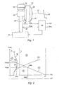
- the vehicle braking device automobile shown schematically in Figure 1 includes a brake pedal 10 connected by a rod 12 to an axial piston of a servomotor 14 pneumatic assistance for the control of a hydraulic master cylinder 16 fed with liquid from brake by a tank 18 and whose outputs 20 are connected to a brake circuit 22 of the wheels of the vehicle.
- the servomotor 14 comprises a front chamber or depression chamber 24, which connected to a source of depression such for example that the intake manifold of the combustion engine internal of the vehicle, and a rear chamber 26 or work chamber that is selectively connected to the depression chamber 24 or porting with the surrounding atmosphere, these two rooms being separated from one another by sealing by a mobile partition whose central part bears the axial piston of the servomotor 14, which itself acts on the primary piston of the master cylinder 16, by via a means of reaction (no represent).
- a pressure sensor 28 of some type appropriate is carried by a fixed wall of the chamber depression 24 for detecting and measuring pressure prevailing in this chamber and a pressure sensor hydraulic 30 of any suitable type is mounted on an output 20 of the master cylinder 16 for detect and measure the hydraulic output pressure of this master cylinder.
- Sensors 28 and 30 produce Pfc and Pmc output signals respectively, applied to inputs of means 32 of information processing, which are programmed to provide the values of the pressure difference ⁇ P between the chambers 24 and 26 of the servomotor 14 and pressure Prc in the working chamber 26.
- the means 32 for processing information are: also programmed for order if necessary means of increase of the hydraulic pressure in the brake system 22, these means being such as a pump or the like, for example part of a circuit type ABS or ESP.
- the working chamber 26 which was previously connected to the depression chamber 24, is isolated from it and put in communication with the ambient atmosphere so the pressure gradually increases in the working room 25 while the pressure in room 24 remains at a value lower than the atmospheric pressure, this value being for example that of the pressure in the intake manifold of the combustion engine internal of the vehicle.
- the pressure difference between rooms 24 and 26 of the servomotor 14 amplifies the effort applied to the control rod 12 so that the effort applied to the primary piston of the master cylinder 16 is equal to the force applied to the control rod 12 multiplied by an amplification coefficient which is itself equal to the pressure difference ⁇ P between chambers of the servomotor multiplied by a constant.
- the pressure in the chamber 26 becomes equal at atmospheric pressure, the amplification by the servomotor is maximum and it is said that the Servomotor is at saturation.
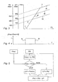
- curve C is the curve saturation characteristic of the servomotor 14, and is constituted by all the points of saturation of the servomotor in an orthonormal frame axes Pfc and Pfmc, Pfc being the pressure or more exactly the relative vacuum level in the chamber of vacuum 24, this vacuum level being equal to 0 when the pressure in chamber 24 is equal to the atmospheric pressure, Pmc being the pressure in output of the master cylinder 16.
- the curve F is a normal braking curve
- zone A located under the curve C is an amplification zone by the actuator 14
- the zone S situated above the curve C is an operating zone of the servomotor in saturation
- zone D on the right of the vertical line L in dashed line is a zone of servomotor failure
- the FD curve is a braking curve in case of leakage between the two chambers 24, 26 of the booster.
- the point searched on curve C is the point Ms having the same ordinate Pmci as the point M of the braking curve.
- This Ms point has a Pfcs abscissa which represents the pressure difference ⁇ P between the two rooms 24, 26 in point M.
- This pressure difference ⁇ P at point M can also write Pmci / ⁇ .
- the braking curve obtained by depression of the pedal 10 is the FD curve for which we see that the relative pressure in the Chamber 24 tends to zero during braking.
- the zone of failure D in the graph of FIG. is delimited to the right of a line L parallel to the Pmc axis.
- the three parallel curve portions 3a, 3b, 3c are obtained for three different values of ⁇ P and therefore Pfc equal for example to 100, 300 and 600 mbars, respectively.
- Detection of Servomotor Failure 14 is used to trigger the transmission of a signal to the driver's attention, and / or to activate a backup system and / or to pilot a medium complementary amplification.
Landscapes
- Engineering & Computer Science (AREA)
- Transportation (AREA)
- Mechanical Engineering (AREA)
- Braking Systems And Boosters (AREA)
- Valves And Accessory Devices For Braking Systems (AREA)
- Braking Arrangements (AREA)
- Supply Devices, Intensifiers, Converters, And Telemotors (AREA)
Description
- à utiliser la courbe caractéristique de saturation du servomoteur, cette courbe étant formée par l'ensemble des points de fonctionnement pour lesquels la pression dans la chambre de travail est égale à la pression atmosphérique et étant représentée par un segment de droite dans un repère orthonormé d'axes Pfc, Pmc, Pfc étant le niveau de vide relatif dans la chambre de dépression du servomoteur et Pmc étant la pression hydraulique en sortie du maitre-cylindre,
- à mesurer les valeurs instantanées Pmci de la pression hydraulique en sortie du maítre-cylindre et Pfci du niveau de vide relatif dans la chambre de dépression du servomoteur,
- à déterminer sur ladite courbe de saturation, lors d'un freinage, le point Ps dont la coordonnée sur l'axe Pfc est la valeur instantanée mesurée du niveau de vide précité,
- à déterminer la coordonnée Pmcs du point Ps sur l'axe Pmc précité,
- et, dans le cas où la valeur instantanée mesurée Pmci est inférieure à la coordonnée Pmcs du point Ps, à prendre comme différence de pression ΔP la valeur mesurée instantanée Pmci de la pression en sortie du maítre-cylindre multipliée par une constante ou la coordonnée sur l'axe Pfc du point de ladite courbe de saturation dont l'autre coordonnée est égale à Pmci,
- et, dans le cas où la valeur mesurée instantanée Pmci est supérieure ou égale à la coordonnée Pmcs du point Ps, à prendre comme différence de pression ΔP la valeur mesurée Pfci du niveau de vide relatif dans la chambre de dépression du servomoteur.
- la figure 1 est une vue schématique partielle d'un dispositif de freinage comprenant un dispositif selon l'invention ;
- la figure 2 est un graphe représentant la courbe caractéristique de saturation d'un servomoteur d'assistance pneumatique et une courbe de freinage ;
- la figure 3 est un graphe représentant la variation de la pression hydraulique en sortie du maítre-cylindre en fonction de l'effort à la pédale ;
- la figure 4 représente la variation d'une valeur binaire correspondant à la saturation du servomoteur, en fonction du temps ; et
- la figure 5 est un organigramme des principales étapes du procédé selon l'invention.
Claims (10)
- Procédé de détermination de la valeur instantanée de l'amplification fournie par un servomoteur d'assistance pneumatique dans un dispositif de freinage pour véhicule automobile, le servomoteur (14) comprenant une chambre de dépression (24) et une chambre de travail (26) séparées par une cloison mobile portant un piston d'actionnement d'un maítre-cylindre hydraulique (16) du dispositif de freinage, ladite amplification instantanée étant proportionnelle à la différence de pression (ΔP) entre les deux chambres du servomoteur et le procédé comprenant des mesures de pression pneumatique dans le servomoteur et de pression hydraulique à la sortie du maítre-cylindre (16), caractérisé en ce qu'il consiste :à utiliser la courbe caractéristique de saturation (C) du servomoteur (14), cette courbe étant formée par l'ensemble des points de fonctionnement pour lesquels la pression dans la chambre de travail (26) est égale à la pression atmosphérique et étant représentée par un segment de droite dans un repère orthonormé d'axes (Pfc, Pmc), Pfc étant le niveau de vide relatif dans la chambre de dépression (24) du servomoteur et Pmc étant la pression hydraulique en sortie du maítre-cylindre (16),à mesurer les valeurs instantanées (Pmci) de la pression hydraulique en sortie du maítre-cylindre (16) et (Pfci) du niveau de vide relatif (Pfc) dans la chambre de dépression du servomoteur,à déterminer sur ladite courbe caractéristique de saturation (C), lors d'un freinage, le point (Ps) dont la coordonnée sur l'axe (Pfc) est la valeur instantanée mesurée (Pfci) du niveau de vide précité,à déterminer la coordonnée (Pmcs) du point (Ps) sur l'axe (Pmc),et, dans le cas où la valeur instantanée mesurée (Pmci) est inférieure à la coordonnée (Pmcs), à prendre comme différence de pression (ΔP) la coordonnée sur l'axe (Pfc) du point de ladite courbe de saturation (C) dont l'autre coordonnée est égale à (Pmci) ou à déterminer la différence de pression (ΔP) à partir de la valeur mesurée instantanée (Pmci) de la pression en sortie du maítre-cylindre multipliée par une constante,et, dans le cas où la valeur instantanée mesurée (Pmci) est supérieure ou égale à la coordonnée (Pmcs) du point (Ps), à prendre comme différence de pression (ΔP) la valeur mesurée (Pfci) du niveau de vide relatif dans la chambre de dépression (24) du servomoteur (14).
- Procédé selon à la revendication 1, caractérisé en ce que ladite constante est égale à l'inverse de la pente α de ladite courbe de saturation (C) dans le repère (Pfc, Pmc).
- Procédé selon à la revendication 1 ou 2, caractérisé en ce qu'il consiste à utiliser un servomoteur (14) de taille réduite, à amplifier l'effort (Fe) appliqué à la pédale au moyen du servomoteur (14) jusqu'à saturation de ce dernier, puis à amplifier encore la pression hydraulique en sortie du maítre-cylindre en utilisant un autre moyen d'amplification de pression tel par exemple qu'une pompe ou analogue et en pilotant ce moyen d'amplification de pression pour lui faire fournir une amplification initiale sensiblement égale à l'amplification fournie en saturation par le servomoteur (14).
- Procédé selon l'une des revendications précédentes, caractérisé en ce qu'il consiste à donner à la différence (Pmci - Pmcs) une valeur binaire égale à 0 quand cette différence est inférieure à 0 et égale à 1 quand cette différence est supérieure à 0, et à surveiller les changements d'état de cette valeur binaire pour déterminer les points de saturation du servomoteur au freinage et au défreinage.
- Procédé selon l'une des revendications précédentes, caractérisé en ce qu'il consiste à déterminer la pression (Prci) instantanée dans la chambre de travail (26) du servomoteur par calcul à partir de la valeur déterminée de la différence de pression (ΔP) et à surveiller les variations de cette pression pour la détection d'une défaillance du servomoteur.
- Procédé selon la revendication 5, caractérisé en ce qu'on détermine la pression dans la chambre de travail (26) du servomoteur par la relation Prci = Pfci - ΔP.
- Procédé selon l'une des revendications précédentes, caractérisé en ce qu'il consiste à détecter une défaillance du servomoteur (14) à partir de l'évolution de la pression instantanée mesurée (Pfci) dans la chambre de dépression (24) lors d'un freinage au-delà d'une valeur limite prédéterminée.
- Dispositif pour l'exécution du procédé décrit dans l'une des revendications précédentes, caractérisé en ce qu'il comprend des moyens (28, 30) de détection et de mesure de la pression dans la chambre de dépression (24) du servomoteur (14) et de la pression hydraulique en sortie du maítre-cylindre (16), et des moyens (32) de traitement de l'information, qui reçoivent les signaux de sortie des moyens (28, 30) de détection et de mesure précités et qui sont programmés pour déterminer sur la courbe de saturation (C) du servomoteur (14), lors d'un freinage, le point (Ps) et sa coordonnée (Pmcs) sur l'axe (Pmc), comparer la valeur instantanée mesurée (Pmci) à la coordonnée (Pmcs) et en fonction du résultat de cette comparaison, déterminer la différence de pression (ΔP) par le produit de la valeur mesurée (Pmci) et d'une constante ou par la valeur mesurée instantanée (Pfci) du niveau de vide dans la chambre de dépression (24), respectivement, la chambre de travail (26) du servomoteur (14) étant dépourvue de moyens de détection et de mesure de pression.
- Dispositif selon la revendication 8, caractérisé en ce que les moyens (32) de traitement de l'information sont programmés pour déterminer par calcul la valeur instantanée de la pression (Prci) dans la chambre de travail (26) du servomoteur.
- Dispositif selon la revendication 8 ou 9, caractérisé en ce que les moyens de traitement de l'information sont programmés pour commander des moyens d'amplification de la pression hydraulique, tels qu'une pompe ou analogue, dans le circuit de freinage (22) lorsque l'amplification maximale fournie par le servomoteur (14) est insuffisante.
Applications Claiming Priority (3)
| Application Number | Priority Date | Filing Date | Title |
|---|---|---|---|
| FR0112173A FR2829738B1 (fr) | 2001-09-20 | 2001-09-20 | Procede et dispositif de determination de l'amplification fournie par un servomoteur d'assistance pneumatique dans un dispositif de freinage |
| FR0112173 | 2001-09-20 | ||
| PCT/FR2002/003065 WO2003024760A2 (fr) | 2001-09-20 | 2002-09-10 | Procede et appareil de determination de l'amplification d'un servomoteur de freinage |
Publications (2)
| Publication Number | Publication Date |
|---|---|
| EP1429947A2 EP1429947A2 (fr) | 2004-06-23 |
| EP1429947B1 true EP1429947B1 (fr) | 2005-09-28 |
Family
ID=8867479
Family Applications (1)
| Application Number | Title | Priority Date | Filing Date |
|---|---|---|---|
| EP02779633A Expired - Lifetime EP1429947B1 (fr) | 2001-09-20 | 2002-09-10 | Procede et appareil de determination de l'amplification d'un servomoteur de freinage |
Country Status (9)
| Country | Link |
|---|---|
| US (1) | US6948416B2 (fr) |
| EP (1) | EP1429947B1 (fr) |
| JP (1) | JP2005502537A (fr) |
| AT (1) | ATE305401T1 (fr) |
| AU (1) | AU2002342978A1 (fr) |
| DE (1) | DE60206401T2 (fr) |
| ES (1) | ES2247386T3 (fr) |
| FR (1) | FR2829738B1 (fr) |
| WO (1) | WO2003024760A2 (fr) |
Families Citing this family (4)
| Publication number | Priority date | Publication date | Assignee | Title |
|---|---|---|---|---|
| DE102005009423A1 (de) * | 2005-03-02 | 2006-09-14 | Robert Bosch Gmbh | Verfahren zum Erkennen des Aussteuerpunkts eines Unterdruck-Bremskraftverstärkers |
| JP2009523647A (ja) * | 2006-01-20 | 2009-06-25 | コンティネンタル・テーベス・アクチエンゲゼルシヤフト・ウント・コンパニー・オッフェネ・ハンデルスゲゼルシヤフト | 真空式制動倍力装置と当該装置を操作する方法 |
| DE102006012146B4 (de) * | 2006-03-16 | 2015-01-08 | Volkswagen Ag | Verfahren zur Berechnung des Drucks in einem Bremskraftverstärker und Bremssystem mit Bremskraftverstärker |
| DE102008011606A1 (de) * | 2008-02-28 | 2009-09-03 | Robert Bosch Gmbh | Vorrichtung und Verfahren zum Erkennen einer Bremsbetätigung |
Family Cites Families (5)
| Publication number | Priority date | Publication date | Assignee | Title |
|---|---|---|---|---|
| FR2617451B1 (fr) * | 1987-06-30 | 1989-10-27 | Bendix France | Procede de reglage de la course morte d'un servomoteur d'assistance au freinage |
| DE4036744A1 (de) * | 1990-11-17 | 1992-05-21 | Teves Gmbh Alfred | Unterdruck-bremskraftverstaerker |
| JP3927256B2 (ja) * | 1996-05-28 | 2007-06-06 | トヨタ自動車株式会社 | 制動力制御装置 |
| DE69737111T8 (de) * | 1996-12-27 | 2007-12-06 | Denso Corp., Kariya | Kraftfahrzeugbremssystem |
| JP3458773B2 (ja) * | 1998-08-24 | 2003-10-20 | トヨタ自動車株式会社 | ブースタ異常判定装置 |
-
2001
- 2001-09-20 FR FR0112173A patent/FR2829738B1/fr not_active Expired - Fee Related
-
2002
- 2002-09-10 AU AU2002342978A patent/AU2002342978A1/en not_active Abandoned
- 2002-09-10 WO PCT/FR2002/003065 patent/WO2003024760A2/fr not_active Ceased
- 2002-09-10 ES ES02779633T patent/ES2247386T3/es not_active Expired - Lifetime
- 2002-09-10 DE DE60206401T patent/DE60206401T2/de not_active Expired - Lifetime
- 2002-09-10 AT AT02779633T patent/ATE305401T1/de not_active IP Right Cessation
- 2002-09-10 JP JP2003528433A patent/JP2005502537A/ja not_active Withdrawn
- 2002-09-10 EP EP02779633A patent/EP1429947B1/fr not_active Expired - Lifetime
- 2002-10-09 US US10/489,939 patent/US6948416B2/en not_active Expired - Fee Related
Also Published As
| Publication number | Publication date |
|---|---|
| DE60206401D1 (de) | 2005-11-03 |
| US20040254708A1 (en) | 2004-12-16 |
| AU2002342978A1 (en) | 2003-04-01 |
| WO2003024760A3 (fr) | 2003-12-11 |
| FR2829738A1 (fr) | 2003-03-21 |
| FR2829738B1 (fr) | 2003-12-19 |
| DE60206401T2 (de) | 2006-06-29 |
| EP1429947A2 (fr) | 2004-06-23 |
| JP2005502537A (ja) | 2005-01-27 |
| ATE305401T1 (de) | 2005-10-15 |
| US6948416B2 (en) | 2005-09-27 |
| ES2247386T3 (es) | 2006-03-01 |
| WO2003024760A2 (fr) | 2003-03-27 |
Similar Documents
| Publication | Publication Date | Title |
|---|---|---|
| JP3210302B2 (ja) | ブースターの限界状態及びペダル踏力の推定工程を有するブレーキ制御方法 | |
| FR2773531A1 (fr) | Systeme d'amplification du freinage | |
| CN101370695A (zh) | 真空制动力放大器及其运行方法 | |
| EP1924473B1 (fr) | Procede d'adaptation de la detection du freinage d'urgence a la reconnaissance de freinages enchaines | |
| FR2586222A1 (fr) | Servo de frein pneumatique | |
| EP1429947A2 (fr) | Procede et appareil de determination de l'amplification d'un servomoteur de freinage | |
| EP1353830B1 (fr) | Servomoteur d'assistance au freinage a assistance hydraulique complementaire | |
| EP1427622B1 (fr) | Procede de calibrage d'un servomoteur d'assistance au freinage | |
| EP2925578B1 (fr) | Procede d'estimation de la pression dans un reservoir a depression d'un servofrein | |
| FR3013657A1 (fr) | Systeme de freinage assiste a servofrein hydraulique | |
| EP3068667B1 (fr) | Procédé d'estimation de la pression dans un réservoir à dépression d'un servofrein | |
| FR2596346A1 (fr) | Systeme hydraulique de freinage | |
| EP3279046A1 (fr) | Circuit de freinage, véhicule comprenant un tel circuit de freinage et procédé de commande du freinage d'un véhicule | |
| FR2714643A1 (fr) | Système de régulation de la dynamique du freinage d'un véhicule. | |
| JP2005516839A (ja) | 真空ブレーキ倍力装置の最大ブースト特性曲線を決定または校正する方法 | |
| EP1231122A1 (fr) | Servomoteur de freinage à position contrôlée | |
| WO2021044091A1 (fr) | Systeme hydraulique et procede associe pour la detection d'une fuite dans la conduite de commande. | |
| FR2966410A1 (fr) | Circuit pneumatique utilise pour l'assistance de freinage d'un vehicule | |
| FR2786531A1 (fr) | Procede et dispositif de commande d'un moteur a combustion interne | |
| EP2098428B1 (fr) | Système de régulation du freinage pour le contrôle de stabilité et de trajectoire d'un véhicule automobile | |
| EP1911648A2 (fr) | Procédé et système d'assistance hydraulique au freinage | |
| JPH06144213A (ja) | ブレーキ装置のシュークリアランス過大時警報装置 | |
| FR2902733A1 (fr) | Dispositif de compensation des absorptions generees dans un systeme de freinage hydraulique | |
| FR2594769A1 (fr) | Dispositif antiblocage de roues de vehicule a moteur comportant une unite de commande pilotee par un detecteur de pression | |
| FR2909956A1 (fr) | Procede de freinage recuperatif pour vehicule hybride tenant compte d'un appui pedale et d'un gradient de pression pour l'application d'un freinage electrique |
Legal Events
| Date | Code | Title | Description |
|---|---|---|---|
| PUAI | Public reference made under article 153(3) epc to a published international application that has entered the european phase |
Free format text: ORIGINAL CODE: 0009012 |
|
| AK | Designated contracting states |
Kind code of ref document: A2 Designated state(s): AT BE BG CH CY CZ DE DK EE ES FI FR GB GR IE IT LI LU MC NL PT SE SK TR |
|
| AX | Request for extension of the european patent |
Extension state: AL LT LV MK RO SI |
|
| 17P | Request for examination filed |
Effective date: 20040611 |
|
| GRAP | Despatch of communication of intention to grant a patent |
Free format text: ORIGINAL CODE: EPIDOSNIGR1 |
|
| GRAS | Grant fee paid |
Free format text: ORIGINAL CODE: EPIDOSNIGR3 |
|
| GRAA | (expected) grant |
Free format text: ORIGINAL CODE: 0009210 |
|
| AK | Designated contracting states |
Kind code of ref document: B1 Designated state(s): AT BE BG CH CY CZ DE DK EE ES FI FR GB GR IE IT LI LU MC NL PT SE SK TR |
|
| PG25 | Lapsed in a contracting state [announced via postgrant information from national office to epo] |
Ref country code: IE Free format text: LAPSE BECAUSE OF FAILURE TO SUBMIT A TRANSLATION OF THE DESCRIPTION OR TO PAY THE FEE WITHIN THE PRESCRIBED TIME-LIMIT Effective date: 20050928 Ref country code: SK Free format text: LAPSE BECAUSE OF FAILURE TO SUBMIT A TRANSLATION OF THE DESCRIPTION OR TO PAY THE FEE WITHIN THE PRESCRIBED TIME-LIMIT Effective date: 20050928 Ref country code: CZ Free format text: LAPSE BECAUSE OF FAILURE TO SUBMIT A TRANSLATION OF THE DESCRIPTION OR TO PAY THE FEE WITHIN THE PRESCRIBED TIME-LIMIT Effective date: 20050928 Ref country code: NL Free format text: LAPSE BECAUSE OF FAILURE TO SUBMIT A TRANSLATION OF THE DESCRIPTION OR TO PAY THE FEE WITHIN THE PRESCRIBED TIME-LIMIT Effective date: 20050928 Ref country code: AT Free format text: LAPSE BECAUSE OF FAILURE TO SUBMIT A TRANSLATION OF THE DESCRIPTION OR TO PAY THE FEE WITHIN THE PRESCRIBED TIME-LIMIT Effective date: 20050928 Ref country code: FI Free format text: LAPSE BECAUSE OF FAILURE TO SUBMIT A TRANSLATION OF THE DESCRIPTION OR TO PAY THE FEE WITHIN THE PRESCRIBED TIME-LIMIT Effective date: 20050928 Ref country code: IT Free format text: LAPSE BECAUSE OF NON-PAYMENT OF DUE FEES Effective date: 20050928 |
|
| REG | Reference to a national code |
Ref country code: GB Ref legal event code: FG4D Free format text: NOT ENGLISH |
|
| REG | Reference to a national code |
Ref country code: CH Ref legal event code: EP |
|
| REG | Reference to a national code |
Ref country code: IE Ref legal event code: FG4D Free format text: LANGUAGE OF EP DOCUMENT: FRENCH |
|
| REF | Corresponds to: |
Ref document number: 60206401 Country of ref document: DE Date of ref document: 20051103 Kind code of ref document: P |
|
| GBT | Gb: translation of ep patent filed (gb section 77(6)(a)/1977) |
Effective date: 20051128 |
|
| PG25 | Lapsed in a contracting state [announced via postgrant information from national office to epo] |
Ref country code: BG Free format text: LAPSE BECAUSE OF FAILURE TO SUBMIT A TRANSLATION OF THE DESCRIPTION OR TO PAY THE FEE WITHIN THE PRESCRIBED TIME-LIMIT Effective date: 20051228 Ref country code: GR Free format text: LAPSE BECAUSE OF FAILURE TO SUBMIT A TRANSLATION OF THE DESCRIPTION OR TO PAY THE FEE WITHIN THE PRESCRIBED TIME-LIMIT Effective date: 20051228 Ref country code: DK Free format text: LAPSE BECAUSE OF FAILURE TO SUBMIT A TRANSLATION OF THE DESCRIPTION OR TO PAY THE FEE WITHIN THE PRESCRIBED TIME-LIMIT Effective date: 20051228 Ref country code: SE Free format text: LAPSE BECAUSE OF FAILURE TO SUBMIT A TRANSLATION OF THE DESCRIPTION OR TO PAY THE FEE WITHIN THE PRESCRIBED TIME-LIMIT Effective date: 20051228 |
|
| PG25 | Lapsed in a contracting state [announced via postgrant information from national office to epo] |
Ref country code: PT Free format text: LAPSE BECAUSE OF FAILURE TO SUBMIT A TRANSLATION OF THE DESCRIPTION OR TO PAY THE FEE WITHIN THE PRESCRIBED TIME-LIMIT Effective date: 20060228 |
|
| NLV1 | Nl: lapsed or annulled due to failure to fulfill the requirements of art. 29p and 29m of the patents act | ||
| REG | Reference to a national code |
Ref country code: ES Ref legal event code: FG2A Ref document number: 2247386 Country of ref document: ES Kind code of ref document: T3 |
|
| REG | Reference to a national code |
Ref country code: IE Ref legal event code: FD4D |
|
| PLBE | No opposition filed within time limit |
Free format text: ORIGINAL CODE: 0009261 |
|
| STAA | Information on the status of an ep patent application or granted ep patent |
Free format text: STATUS: NO OPPOSITION FILED WITHIN TIME LIMIT |
|
| 26N | No opposition filed |
Effective date: 20060629 |
|
| PG25 | Lapsed in a contracting state [announced via postgrant information from national office to epo] |
Ref country code: LI Free format text: LAPSE BECAUSE OF NON-PAYMENT OF DUE FEES Effective date: 20060930 Ref country code: CH Free format text: LAPSE BECAUSE OF NON-PAYMENT OF DUE FEES Effective date: 20060930 Ref country code: MC Free format text: LAPSE BECAUSE OF NON-PAYMENT OF DUE FEES Effective date: 20060930 Ref country code: BE Free format text: LAPSE BECAUSE OF NON-PAYMENT OF DUE FEES Effective date: 20060930 |
|
| REG | Reference to a national code |
Ref country code: CH Ref legal event code: PL |
|
| BERE | Be: lapsed |
Owner name: ROBERT BOSCH G.M.B.H. Effective date: 20060930 |
|
| PG25 | Lapsed in a contracting state [announced via postgrant information from national office to epo] |
Ref country code: EE Free format text: LAPSE BECAUSE OF FAILURE TO SUBMIT A TRANSLATION OF THE DESCRIPTION OR TO PAY THE FEE WITHIN THE PRESCRIBED TIME-LIMIT Effective date: 20050928 |
|
| PG25 | Lapsed in a contracting state [announced via postgrant information from national office to epo] |
Ref country code: LU Free format text: LAPSE BECAUSE OF NON-PAYMENT OF DUE FEES Effective date: 20060910 Ref country code: TR Free format text: LAPSE BECAUSE OF FAILURE TO SUBMIT A TRANSLATION OF THE DESCRIPTION OR TO PAY THE FEE WITHIN THE PRESCRIBED TIME-LIMIT Effective date: 20050928 |
|
| PG25 | Lapsed in a contracting state [announced via postgrant information from national office to epo] |
Ref country code: CY Free format text: LAPSE BECAUSE OF FAILURE TO SUBMIT A TRANSLATION OF THE DESCRIPTION OR TO PAY THE FEE WITHIN THE PRESCRIBED TIME-LIMIT Effective date: 20050928 |
|
| PGRI | Patent reinstated in contracting state [announced from national office to epo] |
Ref country code: IT Effective date: 20091201 |
|
| PGFP | Annual fee paid to national office [announced via postgrant information from national office to epo] |
Ref country code: FR Payment date: 20130918 Year of fee payment: 12 |
|
| PGFP | Annual fee paid to national office [announced via postgrant information from national office to epo] |
Ref country code: GB Payment date: 20140923 Year of fee payment: 13 |
|
| PGFP | Annual fee paid to national office [announced via postgrant information from national office to epo] |
Ref country code: IT Payment date: 20140923 Year of fee payment: 13 |
|
| REG | Reference to a national code |
Ref country code: FR Ref legal event code: ST Effective date: 20150529 |
|
| PG25 | Lapsed in a contracting state [announced via postgrant information from national office to epo] |
Ref country code: FR Free format text: LAPSE BECAUSE OF NON-PAYMENT OF DUE FEES Effective date: 20140930 |
|
| PGFP | Annual fee paid to national office [announced via postgrant information from national office to epo] |
Ref country code: ES Payment date: 20150923 Year of fee payment: 14 |
|
| PG25 | Lapsed in a contracting state [announced via postgrant information from national office to epo] |
Ref country code: IT Free format text: LAPSE BECAUSE OF NON-PAYMENT OF DUE FEES Effective date: 20150910 |
|
| GBPC | Gb: european patent ceased through non-payment of renewal fee |
Effective date: 20150910 |
|
| PG25 | Lapsed in a contracting state [announced via postgrant information from national office to epo] |
Ref country code: GB Free format text: LAPSE BECAUSE OF NON-PAYMENT OF DUE FEES Effective date: 20150910 |
|
| PGFP | Annual fee paid to national office [announced via postgrant information from national office to epo] |
Ref country code: DE Payment date: 20161125 Year of fee payment: 15 |
|
| REG | Reference to a national code |
Ref country code: DE Ref legal event code: R119 Ref document number: 60206401 Country of ref document: DE |
|
| PG25 | Lapsed in a contracting state [announced via postgrant information from national office to epo] |
Ref country code: ES Free format text: LAPSE BECAUSE OF NON-PAYMENT OF DUE FEES Effective date: 20160911 |
|
| PG25 | Lapsed in a contracting state [announced via postgrant information from national office to epo] |
Ref country code: DE Free format text: LAPSE BECAUSE OF NON-PAYMENT OF DUE FEES Effective date: 20180404 |
|
| REG | Reference to a national code |
Ref country code: ES Ref legal event code: FD2A Effective date: 20181126 |