EP1429428A2 - Geerdeter Verbinder - Google Patents
Geerdeter Verbinder Download PDFInfo
- Publication number
- EP1429428A2 EP1429428A2 EP03028579A EP03028579A EP1429428A2 EP 1429428 A2 EP1429428 A2 EP 1429428A2 EP 03028579 A EP03028579 A EP 03028579A EP 03028579 A EP03028579 A EP 03028579A EP 1429428 A2 EP1429428 A2 EP 1429428A2
- Authority
- EP
- European Patent Office
- Prior art keywords
- ground
- connector
- fitting recessed
- fitted
- terminal
- Prior art date
- Legal status (The legal status is an assumption and is not a legal conclusion. Google has not performed a legal analysis and makes no representation as to the accuracy of the status listed.)
- Withdrawn
Links
Images




Classifications
-
- H—ELECTRICITY
- H01—ELECTRIC ELEMENTS
- H01R—ELECTRICALLY-CONDUCTIVE CONNECTIONS; STRUCTURAL ASSOCIATIONS OF A PLURALITY OF MUTUALLY-INSULATED ELECTRICAL CONNECTING ELEMENTS; COUPLING DEVICES; CURRENT COLLECTORS
- H01R13/00—Details of coupling devices of the kinds covered by groups H01R12/70 or H01R24/00 - H01R33/00
- H01R13/648—Protective earth or shield arrangements on coupling devices, e.g. anti-static shielding
-
- H—ELECTRICITY
- H01—ELECTRIC ELEMENTS
- H01R—ELECTRICALLY-CONDUCTIVE CONNECTIONS; STRUCTURAL ASSOCIATIONS OF A PLURALITY OF MUTUALLY-INSULATED ELECTRICAL CONNECTING ELEMENTS; COUPLING DEVICES; CURRENT COLLECTORS
- H01R13/00—Details of coupling devices of the kinds covered by groups H01R12/70 or H01R24/00 - H01R33/00
- H01R13/64—Means for preventing incorrect coupling
- H01R13/645—Means for preventing incorrect coupling by exchangeable elements on case or base
- H01R13/6456—Means for preventing incorrect coupling by exchangeable elements on case or base comprising keying elements at different positions along the periphery of the connector
Definitions
- the present invention relates to a ground joint connector.
- a connector disclosed in JP-A-6-084565 has been known as an example of a conventional ground joint connector.
- the ground joint connector has a structure in which a grounding portion is provided at an end portion of a connector housing which has connecting portions provided therein for fittingly receiving therein mating connectors.
- the ground joint connector also has a grounding terminal including a plurality of terminal pieces which are provided on the grounding terminal in such a manner as to protrude therefrom and which are connected to the grounding portion is installed in the connector housing in such a manner that the respective terminal pieces are made to face the connecting portions.
- the grounding portion is fixed onto a grounding member such as a vehicle body, and thereafter, the mating connectors which are connected to ends of ground wires are fitted in the corresponding connecting portions, whereby the ground wires are grounded together.
- ground wires for assembly that in the event that ground wires are divided into a plurality of groups according to the order of assembly to the vehicle body, it can facilitate the performance of such a process of laying out ground wires. Therefore, in view of the way of preparing ground wires by dividing them into the plurality of groups according to the order of assembly, it has been an approach adopted to deal with the increase in the number of ground circuits so used to increase the number of ground joint connectors rather than increasing the number of poles in a ground joint connector.
- a ground joint connector including: a connector housing; a plurality of connecting portions disposed in the connector housing and configured to be fitted with respective mating connectors; and a ground terminal installed in the connector housing and having a common grounding portion and a plurality of terminal pieces connected to the common grounding portion, wherein the plurality of terminal pieces are arranged to be protruded into the plurality of connecting portions respectively, and wherein the common grounding portion is arranged to be protruded outward from the connector housing.
- reference numeral 10 denotes a ground joint connector according to the invention, in which four mating connectors in total are designed to be fitted therein on two opposite sides thereof.
- the mating connectors include a first connector 30A which is large in size and which is fitted in one side of the ground joint connector 10 and three, that is, second, third and fourth connectors 30B, 30C, 30D which are small in size and which are fitted in the other side of the same connector.
- first to fourth connectors 30A to 30D are basically identical in construction, to represent them, the first connector 30A will be described below.
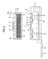
- the first connector 30A has a female connector housing 31 made from a synthetic resin, and as shown in Figs. 2 through 5, the housing 31 is formed into a block-shape configuration having a transversely elongated cross section, in which a plurality of cavities 32 which are each made to face longitudinally are formed in two stages.
- a terminal insertion opening 33 is made to open in a front side of each cavity 32 so that a tab (terminal pieces) 23 of a ground terminal 20, which will be described later, is inserted thereinto.
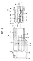
- a female terminal 41 fixedly attached to an end of an ground wire 40 is inserted into each cavity 32 from the rear (a right-hand side in Fig. 5) so as to be accommodated therein while being be locked firstly by a lance 34 provided on a bottom side of the cavity 32 and secondarily by a retainer 35. Note that among the cavities 32, there are some so-called vacant cavities into which no female terminal 41 is inserted.
- a lock arm 36 is provided at a transversely central portion on a top side of the housing 31 in such a manner as to be held between a pair of left and right protection walls 37, and a rib 38 is provided to erect at appropriate positions to prevent the insertion of the connector from a reverse direction.
- second to fourth connectors 30B to 30D are different from the first connector 30A only in size and number of stages where the cavities 32 are provided, like reference numerals are given to locations having like functions to those of the first connector 30A, and the description thereof will be briefly made or omitted.
- the ground joint connector 10 has a connector housing 11 made from the same synthetic resin.
- This connector housing 11 is formed into a flat block-shape configuration and is provided on two opposing sides thereof with fitting surfaces 12, 13 into which mating connectors are fitted.
- a single first fitting recessed portion (connecting portion) 15A is formed in the fitting surface 12 thereof into which the first connector 30A can be fitted.
- a groove 16 and grooves 17 are formed in a ceiling side of the first fitting recessed portion 15 into which the lock arm 36, and the protection walls 37 and the ribs 38 which are formed on the housing 31 of the first connector 30A are inserted, respectively.
- a locking protruding portion 18 is formed in the groove 16 into which the lock arm 36 is inserted so as to be fitted in a locking hole 36A formed in the lock arm 36.
- three, second, third and fourth fitting recessed portions (connecting portions) 15B, 15C, 15D are formed transversely in a straight line in such a manner as to be partitioned by partition walls 19, so that the second to fourth connectors 30B to 30D can be fitted into the respective fitting recessed portions 15B to 15D individually.
- a groove 16 and grooves 17 are formed on a ceiling side of each of the second to fourth fitting recessed portions 15B to 15D into which a lock arm 36, and protection walls 37 and ribs 38 which are provided on each of the second to fourth connectors 30B to 30D are inserted, respectively.
- a locking protruding portion 18 is formed in the groove 16 into which the lock arm 36 is inserted so as to be fitted in a locking hole 36A formed in the lock arm 36.
- a thick intermediate wall 14 is formed between a deeper or rear side of the first fitting recessed portion 15A and deeper or rear sides of the second to fourth fitting recessed portions 15B to 15D.
- the ground terminal 20 is installed in the connector housing 11.
- the ground terminal 20 is formed by folding an elongate bus bar 21 in three folds or stages, and a plurality of tabs 23 are provided on the bus bar 21 placed at a lowermost stage in such a manner as to protrude in an aligned fashion from an edge thereof which is located on a side facing the viewer in Fig. 6, whereas on the bus bars 21 placed at uppermost and middle stages tabs 23 are provided to protrude from both edges.
- a wide ground plate (common grounding portion) 25 having a mounting hole 26 formed therein is formed integrally at a free end of the lowest bus bar 21 in such a manner as to be lowered by a step from the bus bar 21.
- the ground terminal 20 is installed inside the connector housing 11 using insert molding.
- the bus bar 21 which continues in the three-staged fashion is embedded in the intermediate wall 14, and the ground plate 25 is made to protrude outwardly from a lower portion of a side of the connector housing 11 at a position closer to the fitting surface 12, which is one of the fitting surfaces.
- the tabs 23 are made to protrude from the deepest side of the first fitting recessed portion 15A into the interior thereof in two stages.
- the tabs 23 are made to protrude from the deepest sides of the second and fourth fitting recessed portions 15B, 15D in three stages, whereas in the third fitting recessed portion 15C, the tabs 23 are made to protrude from the deepest side thereof in two stages.
- ground joint connector 10 An example of a usage of the ground joint connector 10 according to the invention will be described as below.
- the first connector 30A is fitted into the first fitting recessed portion 15A, and the locking protruding portion 18 is fitted into the locking hole 36 in the lock arm 36, whereby the first connector 30A is locked in the first fitting recessed portion 15A.
- the female terminal 41 accommodated in the first connector 30A is fitted on the corresponding tab 23 protruding from the deepest side of the first fitting recessed portion 15A for connection therewith.
- the second to fourth connectors 30B to 30D are sequentially fitted into the three, second to fourth fitting recessed portions 15B to 15D in the opposite fitting surface 13 and are locked, respectively, in a similar fashion to that in which the first connector 30A is locked.
- female terminals 41 accommodated in the respective connectors 30B to 30D are fitted on the corresponding tabs 23 protruding from the deepest sides of the respective fitting recessed portions 15B to 15D for connection therewith.
- ground plate 25 of the ground terminal 20 is fastened and fixed to the grounding member such as the vehicle body with a bolt 45 (refer to Fig. 1).
- the female terminals 41 accommodated in the respective mating connectors 30A to 30D and hence the ground wires 40 connected to the female terminals 41 are grounded together.
- the four fitting recessed portions 15A to 15D are provided so as to individually fit into the four separate mating connectors 30A to 30D with the single ground terminal 20 being provided to be shared by the respective fitting recessed portions 15A to 15D, the job of fixing the ground plate 25 of the ground terminal 20 to the grounding member such as the vehicle body only has to be carried out once while retaining the advantage of handling the plurality of ground wires 40 which are divided into groups, thereby making it possible to attempt to improve the working efficiency.
Landscapes
- Details Of Connecting Devices For Male And Female Coupling (AREA)
- Multi-Conductor Connections (AREA)
Applications Claiming Priority (2)
| Application Number | Priority Date | Filing Date | Title |
|---|---|---|---|
| JP2002360616A JP3944070B2 (ja) | 2002-12-12 | 2002-12-12 | アースジョイントコネクタ |
| JP2002360616 | 2002-12-12 |
Publications (2)
| Publication Number | Publication Date |
|---|---|
| EP1429428A2 true EP1429428A2 (de) | 2004-06-16 |
| EP1429428A3 EP1429428A3 (de) | 2005-12-21 |
Family
ID=32322117
Family Applications (1)
| Application Number | Title | Priority Date | Filing Date |
|---|---|---|---|
| EP03028579A Withdrawn EP1429428A3 (de) | 2002-12-12 | 2003-12-11 | Geerdeter Verbinder |
Country Status (4)
| Country | Link |
|---|---|
| US (1) | US20050026480A1 (de) |
| EP (1) | EP1429428A3 (de) |
| JP (1) | JP3944070B2 (de) |
| CN (1) | CN1512633A (de) |
Families Citing this family (8)
| Publication number | Priority date | Publication date | Assignee | Title |
|---|---|---|---|---|
| JP2006114245A (ja) * | 2004-10-12 | 2006-04-27 | Sumitomo Wiring Syst Ltd | アースジョイントコネクタ |
| JP5166879B2 (ja) * | 2005-11-25 | 2013-03-21 | 株式会社オートネットワーク技術研究所 | ジョイント部品およびこれを用いたワイヤーハーネス |
| JP5293400B2 (ja) * | 2009-05-21 | 2013-09-18 | 株式会社オートネットワーク技術研究所 | 通信線用の分岐コネクタ |
| JP5428674B2 (ja) * | 2009-09-08 | 2014-02-26 | 株式会社オートネットワーク技術研究所 | アース接続装置及びこれを含むワイヤハーネス |
| JP2011065931A (ja) * | 2009-09-18 | 2011-03-31 | Yazaki Corp | アースジョイントコネクタ |
| EP2654150A1 (de) * | 2012-04-20 | 2013-10-23 | Eaton Industries (Netherlands) B.V. | Stecker zur elektrischen Verbindung zweier Schaltfelder |
| JP6141612B2 (ja) * | 2012-09-21 | 2017-06-07 | 矢崎総業株式会社 | コネクタ |
| JP6057069B2 (ja) * | 2013-01-30 | 2017-01-11 | 第一精工株式会社 | 集合型電気コネクタ及び集合型電気コネクタ製造方法 |
Family Cites Families (7)
| Publication number | Priority date | Publication date | Assignee | Title |
|---|---|---|---|---|
| DE3044131A1 (de) * | 1980-11-24 | 1982-06-16 | Siemens AG, 1000 Berlin und 8000 München | Installationssystem aus konfentionierten leitungen mit steckern sowie verbindungszentren |
| US5151043A (en) * | 1988-12-22 | 1992-09-29 | Siemens Energy & Automation, Inc. | Electrical power distribution busway with isolated ground bus |
| US5102354A (en) * | 1991-03-02 | 1992-04-07 | Molex Incorporated | Filter connector |
| JP2772319B2 (ja) * | 1992-07-13 | 1998-07-02 | 矢崎総業株式会社 | コネクタのシール構造 |
| JPH1012338A (ja) * | 1996-06-24 | 1998-01-16 | Yazaki Corp | ジョイントコネクタ |
| JPH10247566A (ja) * | 1997-02-28 | 1998-09-14 | Mitsumi Electric Co Ltd | コネクタソケット |
| JP2002033168A (ja) * | 2000-07-13 | 2002-01-31 | Sumitomo Wiring Syst Ltd | アース用ジョイントコネクタ |
-
2002
- 2002-12-12 JP JP2002360616A patent/JP3944070B2/ja not_active Expired - Lifetime
-
2003
- 2003-12-09 US US10/729,900 patent/US20050026480A1/en not_active Abandoned
- 2003-12-11 EP EP03028579A patent/EP1429428A3/de not_active Withdrawn
- 2003-12-12 CN CNA2003101205068A patent/CN1512633A/zh active Pending
Also Published As
| Publication number | Publication date |
|---|---|
| CN1512633A (zh) | 2004-07-14 |
| US20050026480A1 (en) | 2005-02-03 |
| JP3944070B2 (ja) | 2007-07-11 |
| JP2004192991A (ja) | 2004-07-08 |
| EP1429428A3 (de) | 2005-12-21 |
Similar Documents
| Publication | Publication Date | Title |
|---|---|---|
| US4753614A (en) | Connecting system for electrical jacks | |
| US4923411A (en) | External connection structure of electric connection box | |
| JP3652610B2 (ja) | コネクタ | |
| US8025538B2 (en) | Joint connector and wiring harness | |
| EP0116991B1 (de) | Sicherungshalter für Messerkontaktsicherung | |
| US6875053B2 (en) | Ground connector and method of mounting it | |
| US7118423B2 (en) | Joint connector structure | |
| US7364449B2 (en) | Joint connector block | |
| EP1049211B1 (de) | Mehrteilige-Verbinder | |
| JP2510465Y2 (ja) | 組合せ合体構造のコネクタハウジング | |
| JP2004179032A (ja) | ジョイントコネクタ | |
| EP1429428A2 (de) | Geerdeter Verbinder | |
| EP0963009A1 (de) | Eine Vorrichtung zur Verhinderung einer fehlerhaften Zusammensetzung eines Verbindergehäuses mit einem Deckel und einen Verbinder mit einer solchen Vorrichtung | |
| US6739920B2 (en) | Joint connector | |
| EP3035451B1 (de) | Erdungsklemme für ein Airbag-Zündsystem | |
| US9972921B2 (en) | Connector with sub-housing and uniting portion | |
| KR20090073878A (ko) | 조인트 스페이서 및 이를 구비한 커넥터 | |
| US20150111444A1 (en) | Joint terminal | |
| EP1172895A1 (de) | Verbinder | |
| US20040121623A1 (en) | Junction box | |
| JP2009266603A (ja) | アースジョイントコネクタ | |
| EP1261070A2 (de) | Anschlussteil und Steckverbinder mit einem solchen Anschlussteil | |
| KR101412322B1 (ko) | 커넥터 | |
| KR20150001577U (ko) | 접지용 단자 | |
| KR200227805Y1 (ko) | 커넥터 |
Legal Events
| Date | Code | Title | Description |
|---|---|---|---|
| PUAI | Public reference made under article 153(3) epc to a published international application that has entered the european phase |
Free format text: ORIGINAL CODE: 0009012 |
|
| AK | Designated contracting states |
Kind code of ref document: A2 Designated state(s): AT BE BG CH CY CZ DE DK EE ES FI FR GB GR HU IE IT LI LU MC NL PT RO SE SI SK TR |
|
| AX | Request for extension of the european patent |
Extension state: AL LT LV MK |
|
| PUAL | Search report despatched |
Free format text: ORIGINAL CODE: 0009013 |
|
| AK | Designated contracting states |
Kind code of ref document: A3 Designated state(s): AT BE BG CH CY CZ DE DK EE ES FI FR GB GR HU IE IT LI LU MC NL PT RO SE SI SK TR |
|
| AX | Request for extension of the european patent |
Extension state: AL LT LV MK |
|
| AKX | Designation fees paid | ||
| STAA | Information on the status of an ep patent application or granted ep patent |
Free format text: STATUS: THE APPLICATION IS DEEMED TO BE WITHDRAWN |
|
| 18D | Application deemed to be withdrawn |
Effective date: 20060622 |
|
| REG | Reference to a national code |
Ref country code: DE Ref legal event code: 8566 |