EP1429350A2 - Verfahren zur Einstellung von Abständen in magnetischen Kreisen - Google Patents
Verfahren zur Einstellung von Abständen in magnetischen Kreisen Download PDFInfo
- Publication number
- EP1429350A2 EP1429350A2 EP03014371A EP03014371A EP1429350A2 EP 1429350 A2 EP1429350 A2 EP 1429350A2 EP 03014371 A EP03014371 A EP 03014371A EP 03014371 A EP03014371 A EP 03014371A EP 1429350 A2 EP1429350 A2 EP 1429350A2
- Authority
- EP
- European Patent Office
- Prior art keywords
- armature
- anchor bolt
- anchor
- plate
- pressing process
- Prior art date
- Legal status (The legal status is an assumption and is not a legal conclusion. Google has not performed a legal analysis and makes no representation as to the accuracy of the status listed.)
- Withdrawn
Links
Images

Classifications
-
- H—ELECTRICITY
- H01—ELECTRIC ELEMENTS
- H01F—MAGNETS; INDUCTANCES; TRANSFORMERS; SELECTION OF MATERIALS FOR THEIR MAGNETIC PROPERTIES
- H01F7/00—Magnets
- H01F7/06—Electromagnets; Actuators including electromagnets
- H01F7/08—Electromagnets; Actuators including electromagnets with armatures
- H01F7/16—Rectilinearly-movable armatures
- H01F7/1638—Armatures not entering the winding
-
- F—MECHANICAL ENGINEERING; LIGHTING; HEATING; WEAPONS; BLASTING
- F02—COMBUSTION ENGINES; HOT-GAS OR COMBUSTION-PRODUCT ENGINE PLANTS
- F02M—SUPPLYING COMBUSTION ENGINES IN GENERAL WITH COMBUSTIBLE MIXTURES OR CONSTITUENTS THEREOF
- F02M51/00—Fuel-injection apparatus characterised by being operated electrically
- F02M51/06—Injectors peculiar thereto with means directly operating the valve needle
- F02M51/061—Injectors peculiar thereto with means directly operating the valve needle using electromagnetic operating means
- F02M51/0625—Injectors peculiar thereto with means directly operating the valve needle using electromagnetic operating means characterised by arrangement of mobile armatures
- F02M51/0635—Injectors peculiar thereto with means directly operating the valve needle using electromagnetic operating means characterised by arrangement of mobile armatures having a plate-shaped or undulated armature not entering the winding
-
- F—MECHANICAL ENGINEERING; LIGHTING; HEATING; WEAPONS; BLASTING
- F02—COMBUSTION ENGINES; HOT-GAS OR COMBUSTION-PRODUCT ENGINE PLANTS
- F02M—SUPPLYING COMBUSTION ENGINES IN GENERAL WITH COMBUSTIBLE MIXTURES OR CONSTITUENTS THEREOF
- F02M61/00—Fuel-injectors not provided for in groups F02M39/00 - F02M57/00 or F02M67/00
- F02M61/16—Details not provided for in, or of interest apart from, the apparatus of groups F02M61/02 - F02M61/14
- F02M61/168—Assembling; Disassembling; Manufacturing; Adjusting
-
- F—MECHANICAL ENGINEERING; LIGHTING; HEATING; WEAPONS; BLASTING
- F02—COMBUSTION ENGINES; HOT-GAS OR COMBUSTION-PRODUCT ENGINE PLANTS
- F02M—SUPPLYING COMBUSTION ENGINES IN GENERAL WITH COMBUSTIBLE MIXTURES OR CONSTITUENTS THEREOF
- F02M63/00—Other fuel-injection apparatus having pertinent characteristics not provided for in groups F02M39/00 - F02M57/00 or F02M67/00; Details, component parts, or accessories of fuel-injection apparatus, not provided for in, or of interest apart from, the apparatus of groups F02M39/00 - F02M61/00 or F02M67/00; Combination of fuel pump with other devices, e.g. lubricating oil pump
- F02M63/0012—Valves
- F02M63/0014—Valves characterised by the valve actuating means
- F02M63/0015—Valves characterised by the valve actuating means electrical, e.g. using solenoid
-
- F—MECHANICAL ENGINEERING; LIGHTING; HEATING; WEAPONS; BLASTING
- F02—COMBUSTION ENGINES; HOT-GAS OR COMBUSTION-PRODUCT ENGINE PLANTS
- F02M—SUPPLYING COMBUSTION ENGINES IN GENERAL WITH COMBUSTIBLE MIXTURES OR CONSTITUENTS THEREOF
- F02M63/00—Other fuel-injection apparatus having pertinent characteristics not provided for in groups F02M39/00 - F02M57/00 or F02M67/00; Details, component parts, or accessories of fuel-injection apparatus, not provided for in, or of interest apart from, the apparatus of groups F02M39/00 - F02M61/00 or F02M67/00; Combination of fuel pump with other devices, e.g. lubricating oil pump
- F02M63/0012—Valves
- F02M63/0031—Valves characterized by the type of valves, e.g. special valve member details, valve seat details, valve housing details
- F02M63/004—Sliding valves, e.g. spool valves, i.e. whereby the closing member has a sliding movement along a seat for opening and closing
-
- F—MECHANICAL ENGINEERING; LIGHTING; HEATING; WEAPONS; BLASTING
- F02—COMBUSTION ENGINES; HOT-GAS OR COMBUSTION-PRODUCT ENGINE PLANTS
- F02M—SUPPLYING COMBUSTION ENGINES IN GENERAL WITH COMBUSTIBLE MIXTURES OR CONSTITUENTS THEREOF
- F02M65/00—Testing fuel-injection apparatus, e.g. testing injection timing ; Cleaning of fuel-injection apparatus
-
- H—ELECTRICITY
- H01—ELECTRIC ELEMENTS
- H01F—MAGNETS; INDUCTANCES; TRANSFORMERS; SELECTION OF MATERIALS FOR THEIR MAGNETIC PROPERTIES
- H01F3/00—Cores, Yokes, or armatures
- H01F3/10—Composite arrangements of magnetic circuits
- H01F3/14—Constrictions; Gaps, e.g. air-gaps
-
- F—MECHANICAL ENGINEERING; LIGHTING; HEATING; WEAPONS; BLASTING
- F02—COMBUSTION ENGINES; HOT-GAS OR COMBUSTION-PRODUCT ENGINE PLANTS
- F02M—SUPPLYING COMBUSTION ENGINES IN GENERAL WITH COMBUSTIBLE MIXTURES OR CONSTITUENTS THEREOF
- F02M2200/00—Details of fuel-injection apparatus, not otherwise provided for
- F02M2200/24—Fuel-injection apparatus with sensors
-
- F—MECHANICAL ENGINEERING; LIGHTING; HEATING; WEAPONS; BLASTING
- F02—COMBUSTION ENGINES; HOT-GAS OR COMBUSTION-PRODUCT ENGINE PLANTS
- F02M—SUPPLYING COMBUSTION ENGINES IN GENERAL WITH COMBUSTIBLE MIXTURES OR CONSTITUENTS THEREOF
- F02M2200/00—Details of fuel-injection apparatus, not otherwise provided for
- F02M2200/80—Fuel injection apparatus manufacture, repair or assembly
-
- F—MECHANICAL ENGINEERING; LIGHTING; HEATING; WEAPONS; BLASTING
- F02—COMBUSTION ENGINES; HOT-GAS OR COMBUSTION-PRODUCT ENGINE PLANTS
- F02M—SUPPLYING COMBUSTION ENGINES IN GENERAL WITH COMBUSTIBLE MIXTURES OR CONSTITUENTS THEREOF
- F02M2200/00—Details of fuel-injection apparatus, not otherwise provided for
- F02M2200/80—Fuel injection apparatus manufacture, repair or assembly
- F02M2200/8061—Fuel injection apparatus manufacture, repair or assembly involving press-fit, i.e. interference or friction fit
-
- Y—GENERAL TAGGING OF NEW TECHNOLOGICAL DEVELOPMENTS; GENERAL TAGGING OF CROSS-SECTIONAL TECHNOLOGIES SPANNING OVER SEVERAL SECTIONS OF THE IPC; TECHNICAL SUBJECTS COVERED BY FORMER USPC CROSS-REFERENCE ART COLLECTIONS [XRACs] AND DIGESTS
- Y10—TECHNICAL SUBJECTS COVERED BY FORMER USPC
- Y10T—TECHNICAL SUBJECTS COVERED BY FORMER US CLASSIFICATION
- Y10T29/00—Metal working
- Y10T29/49—Method of mechanical manufacture
- Y10T29/49002—Electrical device making
- Y10T29/49004—Electrical device making including measuring or testing of device or component part
-
- Y—GENERAL TAGGING OF NEW TECHNOLOGICAL DEVELOPMENTS; GENERAL TAGGING OF CROSS-SECTIONAL TECHNOLOGIES SPANNING OVER SEVERAL SECTIONS OF THE IPC; TECHNICAL SUBJECTS COVERED BY FORMER USPC CROSS-REFERENCE ART COLLECTIONS [XRACs] AND DIGESTS
- Y10—TECHNICAL SUBJECTS COVERED BY FORMER USPC
- Y10T—TECHNICAL SUBJECTS COVERED BY FORMER US CLASSIFICATION
- Y10T29/00—Metal working
- Y10T29/49—Method of mechanical manufacture
- Y10T29/49002—Electrical device making
- Y10T29/4902—Electromagnet, transformer or inductor
Definitions
- solenoid valves are also used.
- actuators designed as solenoid valves Closing elements for relieving a high-pressure control volume loaded control room moves. Through the pressure relief / pressurization of the control chamber there is a stroke movement of the injection valve member within of the fuel injector.
- DE 196 50 865 A1 has a solenoid valve for controlling the fuel pressure in the control pressure chamber of an injection valve, such as a common rail injection system.
- the movement of a valve piston is also determined by the fuel pressure in the control pressure chamber controlled, with which an injection opening of the injection valve is opened or closed becomes.
- the solenoid valve has an electromagnet arranged in a housing part, a movable armature and a movable with the armature, by a closing spring acted upon in the closing direction control valve member with a valve seat of Solenoid valve interacts and thus the fuel outflow from the control pressure chamber controls.
- Such a solenoid valve for controlling the fuel pressure is also known from DE 197 08 104 A1 known in the control pressure chamber of an injection valve.
- the armatures of the solenoid valves according to DE 196 50 865 A1 and DE 197 08 104 A1 are designed as two-part magnet armatures.
- the anchors include one Anchor bolt and an anchor plate slidably received on the anchor bolt.
- Damping devices for use which have a fixed part and one with the anchor plate include moving part.
- the stationary part can by an overstroke are formed, which limits the maximum path by which the anchor plate extends can move the anchor bolt.
- the movable part is fixed by one Part facing projection formed on an anchor plate.
- the overstroke can through the face of a leading the anchor bolt, in the housing of the solenoid valve stationary clamped or by a part upstream of the slide, such as for example, an annular disc can be formed.
- a hydraulic damping chamber When the anchor plate approaches the overstroke is created between the mutually facing end faces of the anchor plate and the overstroke stop a hydraulic damping chamber.
- the one in the hydraulic Fuel contained in the damping chamber creates a force that moves the anchor plate counteracts, so that the reverberation of the anchor plate is strongly dampened.
- the DE 101 00 422.2 has a solenoid valve for controlling an injection valve of an internal combustion engine to the subject.
- the solenoid valve includes a movable armature with anchor plate and anchor bolt and one moved with the anchor and with a valve seat cooperating control valve part for opening and closing a fuel drain channel a control pressure chamber in the injection valve.
- the anchor plate is under action their inertial mass in the closing direction of the control valve member, against the clamping force a return spring acting on the anchor plate is slidable on the anchor bolt stored.
- the reverberation is by means of a hydraulic damping device the anchor plate can be damped on the anchor bolt during aerodynamic displacement.
- the damping device comprises a fixed part and one with the anchor plate moving part.
- the part moved with the anchor plate is formed by an actuator, which is arranged on a section of the armature plate facing away from the electromagnet is and for setting the maximum sliding path of the anchor plate relative to one the end face of the anchor plate facing the electromagnet in the sliding direction of the anchor plate is adjustable.
- the actuator is an internally threaded one Screw member formed, which from a penetrated by the anchor bolt and screwed through a section of the anchor plate provided with an external thread is.
- a pre-assembled magnet armature assembly a Including anchor plate and an anchor bolt, inserted into a pressing tool.
- the press tool can by pressing or pressing the relative position between the anchor plate and the anchor bolt of the magnet armature assembly.
- To Accurately calibrated inserts or spacers are used, which however after the adjustment process, d. H. the setting of a defined, the relative position between Anchor plate and anchor bolt defining dimension, are removed again.
- the before Insert into the press tool on the pre-assembled magnet armature assembly Relative position between anchor bolt and anchor plate is readjusted exactly and on a target relative position is set.
- the magnet armature assembly recalibrated in this way can be used within a solenoid valve assembly with which Have fuel injectors controlled by fuel injection systems. This allows For fuel injectors that are actuated via a solenoid valve, previously used classified ones Avoid setting rings or post-processing. For mass production Fuel injectors for fuel injection systems for internal combustion engines, the waiver of shims or other adjustment elements represents a significant Cost savings there.
- a magnet armature assembly 1 is shown.
- the magnet armature 1 comprises an anchor plate 2, the first, upward-facing end face 3 and a second, after End face 4 pointing below.
- the anchor plate 2 also has an anchor plate bore 5 on.
- the magnet armature 1 further comprises an anchor bolt 7, which is the anchor plate bore 5 penetrates the anchor plate 2.
- the anchor plate 2 and the anchor bolt 7 are fitted into one another via a press fit 6.
- a first anchor bolt end face 8 has a tolerance-related dimension 23 with respect to FIG first end face 3 of the anchor plate 2 in front. Between the second end face 4 of the anchor plate 2 and a second anchor bolt end face 9, a first defined dimension 24 becomes very precise set.
- a second, tolerant measure 26 denotes the distance between the first anchor bolt end face 8 and the first end face 14 facing the anchor plate 2 of the magnetic core 10 and is individually specified by the component.
- the residual air gap 20 (h) is the between the second end face 4 of the armature plate 2 and the first end face 14 of the magnetic core 10 sets.
- the residual air gap 20 is to be set to ⁇ m accuracy.
- a first one Dimension 25, which is subject to tolerance, is produced depending on the production between the 2nd end of the anchor bolt 9 and the end face 14 of the magnetic core 10.
- the lower, second anchor bolt end face 9 is acted upon by an actuating force 22 (F MAGN ), which corresponds to the force that must be generated by the magnetic circuit.
- the armature bolt 7 stands between these components of the magnet armature 1 a relative position 21.
- the anchor bolt 7 of the magnet armature 1 is in one Through opening 11 of a magnetic core 10 is added.
- the passage opening 11 of the magnetic core 10 has a game 12, so that a guided vertical movement of the magnet armature 1 relative to the magnet core 10 is possible. That of the peripheral surface of the armature bolt 7 of the magnet armature 1 facing side of the through opening 11 marked with reference number 13.
- the magnetic core 10, in which a magnetic coil 17 is included, comprises a first end face 14 and a second end face 15 of the magnetic core 10, a recess 16 is formed which is annular configured solenoid coil 17 takes.
- Magnetic coil 17 having a magnetic circuit arises with reference numerals 19 marked magnetic flux around the magnetic coil 17 of the magnetic core 10 on.
- the magnetic flux 19 that occurs when the magnetic coil 17 is energized causes a relative movement of the armature plate 2 of the magnet armature 1 to the first end face 14 of the magnetic core 10.
- the setting of the residual air gap 20 (h) must be carried out with ⁇ m accuracy, as the the force resulting from the magnetic flux 19 strongly changes on the armature 1 with the dimension h. This change is approximately inversely proportional to the square of h.
- the Residual air gap 20 must be set with the necessary accuracy.
- the defined dimension 27 is set precisely.
- Adherence to the defined dimension 24 can be achieved by means of an optical measuring method by an optical measuring device, for example, which is assigned to the pressing tool is to be monitored continuously. All come in the ⁇ m range as measuring methods exact measurement methods in question, for example inductive, capacitive, optical or magnetic Measurement methods.
- the tolerances of the components of the magnet armature 1, i.e. H. the anchor plate 2 or the anchor bolt 7 can be dimensioned higher, which is the manufacture of these components in terms of processing time and manufacturing costs favorably influenced. If the tolerances are widened, there are several supplements or calibrated ones Use spacers.
- the first defined dimension 24 is measured however, preferably during the adjustment process, i.e. the setting of the relative position 21 between the anchor plate 2 and the anchor bolt 7. Is the first defined dimension 24, in which 1 as the distance between the second anchor bolt end face 9 and the second end face 4 of the anchor plate 2, reached, the pressing to this Time ended.
- the anchor plate 2 When performing the subsequent pressing process after the pre-assembly of the magnet armature 1, comprising the anchor plate 2 and the anchor bolt 7, the anchor plate 2 be inserted in a press device 30. Then the application takes place of the anchor bolt 2 passing through the anchor plate bore 5 on the anchor plate bore 5 one of its end faces 8 and 9 with a pressing force 31 (F). The one on the end faces 8 or 9 of the anchor bolt 7 acting pressing force of the pressing device causes a relative movement of the anchor bolt 7 to the anchor plate bore 5 on the press fit 6, which is in the Setting the pre-assembly of the magnet armature 1.
- the press device 30 is applied to one of the end faces 8 and 9 of the anchor bolt 7 pressing force 31 long until the first defined dimension 24 between the second anchor bolt face 9 and the second end face 4 of the anchor plate 2 is set.
- the first defined dimension 24 is the dimension to be precisely set.
- the magnetic force 22 acts on the second anchor bolt end 9 of the anchor bolt. If the actuating force 22 (F MAGN ) acts on the first anchor bolt end 8 of the anchor bolt 7, which is also a possible application, the second defined dimension 27 would be the exact dimension to be set.
- the magnet armature 1 can without the use of shims or without the use of classified adjusting rings, which were previously customary in fuel injectors for adapting the residual air gap 20 be used to be integrated into the solenoid valve assembly. Because of the defined Position of the second end face 15 of the magnetic core 10 in the injector body and due to the defined installation position of the magnet armature 1 in the injector body, turns out at the Assembly of a magnet armature pressed with the method proposed according to the invention 1 in the injector body the distance h, d.
- the first defined measure which according to the proposed method is set precisely, is individually for exactly one Part that has certain geometry tolerances according to its production. is the first defined dimension 24 is precisely set, so are the injector body and the magnet armature 1 paired and only to be installed together. For the next injector body, the one with other manufacturing deviations, another first will also be defined Set dimension 24 and the next magnet armature assembly with a something else, the first defined dimension that exactly matches another injector body 24 pressed. A further injector body and a further magnet armature 1 are thus paired, i.e. can only be installed together.
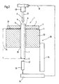
- the pressing device which is identified by reference numerals 30 is identified.
- the pressing device generates a pressing force 31 (F), which in the 2, the first anchor bolt end face 8 of the anchor bolt 7 is acted upon.
- the anchor plate 2 lies with its second end face 4 on one end face 33 of a receiving device 32 of the pressing device 30.
- the anchor bolt 7, is received in an anchor plate bore 5 by means of a press fit 6 the pressing force 31 (F) applied by the pressing device 30 is applied until via a probe 35, which lies opposite the second anchor bolt end face 9 of the anchor bolt 7, it is determined that the first defined dimension 24 has reached the desired value.
- the target value of the first defined dimension 24 was determined beforehand and depends on the individual component tolerances of the preassembled magnet armature assembly 1.
- the press device 30 generates a pressing force 31 (F) that the anchor bolt at a constant speed 7 pushes through the anchor plate 2.
- the pressing force 31 (F) also attack on the second anchor bolt end face 9.
- the second defined dimension 27 shown in the illustration according to FIG. 1 is exactly that Dimension to be set.
Landscapes
- Engineering & Computer Science (AREA)
- Chemical & Material Sciences (AREA)
- Combustion & Propulsion (AREA)
- Mechanical Engineering (AREA)
- General Engineering & Computer Science (AREA)
- Physics & Mathematics (AREA)
- Electromagnetism (AREA)
- Power Engineering (AREA)
- Composite Materials (AREA)
- Manufacturing & Machinery (AREA)
- Fuel-Injection Apparatus (AREA)
- Permanent Field Magnets Of Synchronous Machinery (AREA)
Abstract
Description
- Figur 1
- eine vormontierte Magnetankerbaugruppe samt eines Magnetkerns und definierte sowie toleranzbehafteter Maße und
- Figur 2
- den schematischen Aufbau einer Presseinrichtung zum Verpressen einer Magnetankerbaugruppe auf ein definiertes Maß.
- 1
- Magnetanker
- 2
- Ankerplatte
- 3
- erste Stirnseite
- 4
- zweite Stirnseite
- 5
- Ankerplattenbohrung
- 6
- Presssitz
- 7
- Ankerbolzen
- 8
- erste Ankerbolzenstirnseite
- 9
- zweite Ankerbolzenstirnseite
- 10
- Magnetkern
- 11
- Durchgangsöffnung
- 12
- Spiel
- 13
- Öffnungswandung
- 14
- erste Stirnseite Magnetkern
- 15
- zweite Stirnseite Magnetkern
- 16
- Ausnehmung
- 17
- Magnetspule
- 18
- Stirnseite Magnetspule
- 19
- magnetischer Fluss bei Bestromung
- 20
- h (Restluftspalt)
- 21
- Relativlage Ankerplatte 2 / Ankerbolzen 7
- 22
- Betätigungskraft (FMAGN)
- 23
- Hilfsmaß
- 24
- erstes definiertes Maß
- 25
- erstes toleranzbehaftetes Maß
- 26
- zweites toleranzbehaftetes Maß
- 27
- zweites definiertes Maß
- 30
- Pressvorrichtung
- 31
- Presskraft
- 32
- Aufnahmevorrichtung
- 33
- Stirnseite
- 34
- Pressbett
- 35
- Messtaster
- 36
- Aufnahmebohrung
- 37
- Oberseite Messtaster
- 38
- Wegmesssystem
- 39
- Ansteuerleitung
- 40
- Pressstempel
Claims (12)
- Verfahren zur Einstellung eines Abstandes (20) innerhalb eines magnetischen Kreises, insbesondere des Abstandes (20) zwischen einem Magnetanker (1) und einem Magnetkern (10), wobei der Magnetanker (1) eine Ankerplatte (2) und einen Ankerbolzen (7) aufweist, die in einer Relativlage (21) miteinander gefügt werden, dadurch gekennzeichnet, dass nach der Montage des Magnetankers (1) aus Ankerplatte 2 und Ankerbolzen 7 die Relativlage (21) zwischen der Ankerplatte (2) und dem Ankerbolzen (7) im Rahmen eines Pressvorganges auf ein erstes definiertes Maß (24) oder ein zweites definiertes Maß (27) eingestellt werden.
- Verfahren gemäß Anspruch 1, dadurch gekennzeichnet, dass während des Pressvorganges das erste definierte, die Relativlage (21) kennzeichnende Maß (24) mittels eines Wegmesssystemes überwacht wird.
- Verfahren gemäß Anspruch 1, dadurch gekennzeichnet, dass der Pressvorgang zur Einstellung der Relativlage (21) in einem Presswerkzeug mittels in dieses einlegbarer, kalibrierter Abstandhalter erfolgt.
- Verfahren gemäß Anspruch 1, dadurch gekennzeichnet, dass der Pressvorgang zur Einstellung der Relativlage (21) im Presswerkzeug mittels in dieser einlegbarer kalibrierter Beilagen erfolgt.
- Verfahren gemäß der Ansprüche 3 und 4, dadurch gekennzeichnet, dass die kalibrierten Abstandhalter oder die kalibrierten Beilagen nach dem Pressvorgang am montierten Magnetanker (1) von diesem entfernt werden.
- Verfahren gemäß Anspruch 1, dadurch gekennzeichnet, dass beim Pressvorgang der vormontierten Magnetankerbaugruppe (1) die Ankerplatte (2) auf einer Stirnseite (33) einer Aufnahmevorrichtung (32) aufliegt und der Ankerbolzen (7) an einer seiner Ankerbolzenstirnseiten (8, 9) mit einer Presskraft (31) (F) beaufschlagt wird.
- Verfahren gemäß Anspruch 1, dadurch gekennzeichnet, dass beim Pressvorgang der vormontierten Magnetankerbaugruppe (1) der Ankerbolzen (7) fixiert wird und die Ankerplatte (2) mit einer Presskraft (31) (F) beaufschlagt wird.
- Verfahren gemäß Anspruch 6, dadurch gekennzeichnet, dass während des Pressvorganges an der vormontierten Magnetankerbaugruppe (1) der Ankerbolzen (7) mit konstanter Geschwindigkeit durch eine Ankerplattenbohrung (5) der Ankerplatte (2) geschoben wird.
- Verfahren gemäß Anspruch 1, dadurch gekennzeichnet, dass während des Pressvorganges des Magnetankers (1) ein Presssitz (6) der Ankerplatte (2) an der Mantelfläche des Ankerbolzens (7) hinsichtlich der Relativlage (21) der Ankerplatte (2) an der Umfangsfläche des Ankerbolzens (7) beeinflusst wird.
- Verfahren gemäß Anspruch 1, dadurch gekennzeichnet, dass während des Pressvorganges, das zweite definierte, die Relativlage (21) zwischen dem Ankerbolzen (7) und der Ankerplatte (2) kennzeichnende Maß (27) mittels eines Messtasters (35) kontinuierlich überwacht wird.
- Verfahren gemäß Anspruch 10, dadurch gekennzeichnet, dass die Presskraft (31) (F) an der ersten Ankerbolzenstirnseite (8) des Ankerbolzens (7) zur Einstellung des zweiten definierten Maßes (27) eingeleitet wird.
- Verfahren gemäß einem oder mehrerer der vorhergehenden Ansprüche, dadurch gekennzeichnet, dass die Presskraft (31) (F) solange auf die vormontierte Magnetankerbaugruppe (1) einwirkt, bis entweder das erste definierte Maß (24) oder das zweite definierte Maß (27) erreicht sind und über den Messtaster (35) und ein diesem nachgeordnetes Wegmesssystem (38) der Pressvorgang beendet wird.
Applications Claiming Priority (2)
| Application Number | Priority Date | Filing Date | Title |
|---|---|---|---|
| DE10257380 | 2002-12-09 | ||
| DE10257380A DE10257380A1 (de) | 2002-12-09 | 2002-12-09 | Verfahren zur Einstellung von Abständen in magnetischen Kreisen |
Publications (2)
| Publication Number | Publication Date |
|---|---|
| EP1429350A2 true EP1429350A2 (de) | 2004-06-16 |
| EP1429350A3 EP1429350A3 (de) | 2011-11-02 |
Family
ID=32319006
Family Applications (1)
| Application Number | Title | Priority Date | Filing Date |
|---|---|---|---|
| EP03014371A Withdrawn EP1429350A3 (de) | 2002-12-09 | 2003-06-26 | Verfahren zur Einstellung von Abständen in magnetischen Kreisen |
Country Status (4)
| Country | Link |
|---|---|
| US (1) | US20040111871A1 (de) |
| EP (1) | EP1429350A3 (de) |
| JP (1) | JP2004190677A (de) |
| DE (1) | DE10257380A1 (de) |
Cited By (1)
| Publication number | Priority date | Publication date | Assignee | Title |
|---|---|---|---|---|
| EP1744054A1 (de) * | 2005-07-12 | 2007-01-17 | Robert Bosch Gmbh | Aktive Ankerhubeinstellung bei Kraftstoffinjektoren |
Families Citing this family (2)
| Publication number | Priority date | Publication date | Assignee | Title |
|---|---|---|---|---|
| US8387945B2 (en) | 2009-02-10 | 2013-03-05 | Engineering Matters, Inc. | Method and system for a magnetic actuator |
| JP6450704B2 (ja) * | 2016-04-28 | 2019-01-09 | ファナック株式会社 | 複数の機械による製造状況を調整する製造調整システム |
Family Cites Families (8)
| Publication number | Priority date | Publication date | Assignee | Title |
|---|---|---|---|---|
| CH674485A5 (de) * | 1988-03-11 | 1990-06-15 | Saphirwerk Ind Prod | |
| DE19650865A1 (de) * | 1996-12-07 | 1998-06-10 | Bosch Gmbh Robert | Magnetventil |
| DE19708104A1 (de) * | 1997-02-28 | 1998-09-03 | Bosch Gmbh Robert | Magnetventil |
| DE19723520A1 (de) * | 1997-06-05 | 1998-12-10 | Daimler Benz Ag | Verfahren zum lagerichtigen Fixieren einer Ankerplatte einer elektromagnetischen Ventilsteuerung, sowie elektromagnetische Ventilsteuerung |
| IT1293433B1 (it) * | 1997-07-11 | 1999-03-01 | Elasis Sistema Ricerca Fiat | Valvola di dosaggio registrabile per un iniettore di combustibile per motori a combustione interna, e relativo metodo di registrazione. |
| WO1999022384A1 (en) * | 1997-10-28 | 1999-05-06 | Siemens Automotive Corporation | Method of joining a member of soft magnetic material to a guiding shaft |
| FR2792108B1 (fr) * | 1999-04-12 | 2001-05-04 | Schneider Electric Sa | Electroaimant a courant continu |
| DE10100422A1 (de) * | 2001-01-08 | 2002-07-11 | Bosch Gmbh Robert | Magnetventil zur Steuerung eines Einspritzventils einer Brennkraftmaschine |
-
2002
- 2002-12-09 DE DE10257380A patent/DE10257380A1/de not_active Withdrawn
-
2003
- 2003-06-26 EP EP03014371A patent/EP1429350A3/de not_active Withdrawn
- 2003-12-08 US US10/728,833 patent/US20040111871A1/en not_active Abandoned
- 2003-12-09 JP JP2003410932A patent/JP2004190677A/ja active Pending
Cited By (1)
| Publication number | Priority date | Publication date | Assignee | Title |
|---|---|---|---|---|
| EP1744054A1 (de) * | 2005-07-12 | 2007-01-17 | Robert Bosch Gmbh | Aktive Ankerhubeinstellung bei Kraftstoffinjektoren |
Also Published As
| Publication number | Publication date |
|---|---|
| US20040111871A1 (en) | 2004-06-17 |
| JP2004190677A (ja) | 2004-07-08 |
| EP1429350A3 (de) | 2011-11-02 |
| DE10257380A1 (de) | 2004-07-15 |
Similar Documents
| Publication | Publication Date | Title |
|---|---|---|
| EP1266135B1 (de) | Magnetventil zur steuerung eines einspritzventils einer brennkraftmaschine | |
| DE10249161B3 (de) | Vorrichtung zur Einstellung eines Ankerhubs eines Magnetventils | |
| EP1259729A2 (de) | Magnetventil zur steuerung eines einspritzventils einer brennkraftmaschine | |
| DE102005017243A1 (de) | Elektromagnetisch betätigtes Durchflußsteuerventil | |
| EP2307697A1 (de) | Kraftstoffinjektor mit zweiteiligem magnetanker | |
| WO2007128604A1 (de) | Magnetventil mit selbstzentrierendem ankerbolzen | |
| DE19956256B4 (de) | Leerhubeinstellung zwischen einem Aktor und einem Übertragungselement eines Ventils in einem Kraftstoffinjektor | |
| EP1382839B1 (de) | Ankerbaugruppe für Kraftstoffinjektoren | |
| EP2201237A1 (de) | Steuerventil für einen kraftstoffinjektor | |
| EP1744054B1 (de) | Aktive Ankerhubeinstellung bei Kraftstoffinjektoren | |
| EP2025922A2 (de) | Kraftstoffeinspritzventil für Brennkraftmaschinen | |
| WO2010009925A1 (de) | Ankerbolzen für magnetventil | |
| DE10257380A1 (de) | Verfahren zur Einstellung von Abständen in magnetischen Kreisen | |
| DE10152268A1 (de) | Einspritzventil | |
| EP2541036A1 (de) | Schaltventil, Verfahren zum Herstellen eines Schaltventils und Kraftstoffinjektor mit einem Schaltventil | |
| EP1875066B1 (de) | Vormontierte ankergruppe für common rail injektor | |
| WO2010000516A1 (de) | Konkave luftspaltbegrenzung bei magnetventil | |
| EP3346121B1 (de) | Magnetventil für ein kraftstoffeinspritzsystem und kraftstoffhochdruckpumpe | |
| DE102005058302A1 (de) | Verformungsoptimierte Ankerführung für Magnetventile | |
| DE10202324A1 (de) | Magnetventil und Verfahren zu seiner Herstellung | |
| WO2005095786A1 (de) | Pumpe-düse-einheit mit magnetventil und verfahren zur montage des magnetventils | |
| DE10146141A1 (de) | Magnetventil | |
| DE102017219568A1 (de) | Verfahren zum Steuern eines Kraftstoffinjektors | |
| WO2012130452A1 (de) | Einspritzventil | |
| EP1325215A1 (de) | Verfahren zur herstellung eines elektromagnetischen aktuators |
Legal Events
| Date | Code | Title | Description |
|---|---|---|---|
| PUAI | Public reference made under article 153(3) epc to a published international application that has entered the european phase |
Free format text: ORIGINAL CODE: 0009012 |
|
| AK | Designated contracting states |
Kind code of ref document: A2 Designated state(s): AT BE BG CH CY CZ DE DK EE ES FI FR GB GR HU IE IT LI LU MC NL PT RO SE SI SK TR |
|
| AX | Request for extension of the european patent |
Extension state: AL LT LV MK |
|
| PUAL | Search report despatched |
Free format text: ORIGINAL CODE: 0009013 |
|
| AK | Designated contracting states |
Kind code of ref document: A3 Designated state(s): AT BE BG CH CY CZ DE DK EE ES FI FR GB GR HU IE IT LI LU MC NL PT RO SE SI SK TR |
|
| AX | Request for extension of the european patent |
Extension state: AL LT LV MK |
|
| RIC1 | Information provided on ipc code assigned before grant |
Ipc: F02M 63/00 20060101ALI20110929BHEP Ipc: H01F 7/16 20060101ALI20110929BHEP Ipc: H01F 3/14 20060101ALI20110929BHEP Ipc: F02M 65/00 20060101ALI20110929BHEP Ipc: F02M 61/16 20060101ALI20110929BHEP Ipc: F02M 51/06 20060101ALI20110929BHEP Ipc: H01F 7/127 20060101AFI20110929BHEP |
|
| 17P | Request for examination filed |
Effective date: 20120502 |
|
| AKX | Designation fees paid |
Designated state(s): DE FR GB IT |
|
| STAA | Information on the status of an ep patent application or granted ep patent |
Free format text: STATUS: THE APPLICATION IS DEEMED TO BE WITHDRAWN |
|
| 18D | Application deemed to be withdrawn |
Effective date: 20140103 |