EP1429343A1 - Sicherheitsbehälter einer Kernkraftanlage - Google Patents
Sicherheitsbehälter einer Kernkraftanlage Download PDFInfo
- Publication number
- EP1429343A1 EP1429343A1 EP03021849A EP03021849A EP1429343A1 EP 1429343 A1 EP1429343 A1 EP 1429343A1 EP 03021849 A EP03021849 A EP 03021849A EP 03021849 A EP03021849 A EP 03021849A EP 1429343 A1 EP1429343 A1 EP 1429343A1
- Authority
- EP
- European Patent Office
- Prior art keywords
- condensation
- chamber
- condensation chamber
- pressure
- tube
- Prior art date
- Legal status (The legal status is an assumption and is not a legal conclusion. Google has not performed a legal analysis and makes no representation as to the accuracy of the status listed.)
- Granted
Links
- 238000009833 condensation Methods 0.000 claims abstract description 117
- 230000005494 condensation Effects 0.000 claims abstract description 117
- 239000000110 cooling liquid Substances 0.000 claims description 10
- 238000009434 installation Methods 0.000 abstract 1
- 239000007789 gas Substances 0.000 description 18
- XLYOFNOQVPJJNP-UHFFFAOYSA-N water Substances O XLYOFNOQVPJJNP-UHFFFAOYSA-N 0.000 description 15
- 239000002826 coolant Substances 0.000 description 10
- IJGRMHOSHXDMSA-UHFFFAOYSA-N Atomic nitrogen Chemical compound N#N IJGRMHOSHXDMSA-UHFFFAOYSA-N 0.000 description 8
- 238000001816 cooling Methods 0.000 description 8
- 238000009835 boiling Methods 0.000 description 5
- 239000003990 capacitor Substances 0.000 description 4
- 229910052757 nitrogen Inorganic materials 0.000 description 4
- 238000010276 construction Methods 0.000 description 3
- 239000001257 hydrogen Substances 0.000 description 3
- 229910052739 hydrogen Inorganic materials 0.000 description 3
- 230000007257 malfunction Effects 0.000 description 3
- UFHFLCQGNIYNRP-UHFFFAOYSA-N Hydrogen Chemical compound [H][H] UFHFLCQGNIYNRP-UHFFFAOYSA-N 0.000 description 2
- 230000015572 biosynthetic process Effects 0.000 description 2
- -1 air or nitrogen Chemical compound 0.000 description 1
- 230000000694 effects Effects 0.000 description 1
- 230000002349 favourable effect Effects 0.000 description 1
- 230000017525 heat dissipation Effects 0.000 description 1
- 150000002431 hydrogen Chemical class 0.000 description 1
- 239000011261 inert gas Substances 0.000 description 1
- 238000005259 measurement Methods 0.000 description 1
- 238000012986 modification Methods 0.000 description 1
- 230000004048 modification Effects 0.000 description 1
- 229920006395 saturated elastomer Polymers 0.000 description 1
- 239000007921 spray Substances 0.000 description 1
Images


Classifications
-
- G—PHYSICS
- G21—NUCLEAR PHYSICS; NUCLEAR ENGINEERING
- G21C—NUCLEAR REACTORS
- G21C9/00—Emergency protection arrangements structurally associated with the reactor, e.g. safety valves provided with pressure equalisation devices
- G21C9/004—Pressure suppression
- G21C9/012—Pressure suppression by thermal accumulation or by steam condensation, e.g. ice condensers
-
- Y—GENERAL TAGGING OF NEW TECHNOLOGICAL DEVELOPMENTS; GENERAL TAGGING OF CROSS-SECTIONAL TECHNOLOGIES SPANNING OVER SEVERAL SECTIONS OF THE IPC; TECHNICAL SUBJECTS COVERED BY FORMER USPC CROSS-REFERENCE ART COLLECTIONS [XRACs] AND DIGESTS
- Y02—TECHNOLOGIES OR APPLICATIONS FOR MITIGATION OR ADAPTATION AGAINST CLIMATE CHANGE
- Y02E—REDUCTION OF GREENHOUSE GAS [GHG] EMISSIONS, RELATED TO ENERGY GENERATION, TRANSMISSION OR DISTRIBUTION
- Y02E30/00—Energy generation of nuclear origin
- Y02E30/30—Nuclear fission reactors
Definitions
- DE 198 09 000 C1 is an innovative construction and security concept for a boiling water reactor known.
- the reactor pressure vessel is arranged centrally in a safety vessel.
- a closed condensation chamber and one above it Flood basin provided. This is open to a central area, in which the reactor pressure vessel is arranged and forms a pressure chamber with it.
- the building condenser stands with a coolant from above of the security container arranged cooling pool in connection and is used for Dissipation of the heat from the pressure chamber.
- the efficiency of the building capacitor is sensitive to the presence of non-condensable gases such as nitrogen or hydrogen, where the latter can arise particularly in the case of extreme accidents.
- the non-condensable Gases reduce the ability of the building condenser to heat to discharge any steam that may be present in the pressure chamber into the cooling basin.
- Hydrogen accumulates due to its low specific weight in the upper area of the pressure chamber so that just around the building condenser has a high concentration of non-condensable Gases can be present, which leads to an increase in pressure in the containment.
- the in the safety container described in this document has a condensation chamber, a pressure chamber and one arranged in the upper region of the pressure chamber Building condenser, wherein a discharge pipe is also provided, the fluidically the upper area of the pressure chamber with the condensation chamber connects to and target the non-condensable gases direct path from the upper area of the pressure chamber into the condensation chamber derive.
- condensation tubes essentially consist of a vertical one extending pipe, the upper end of which is connected to the pressure chamber and the lower end of which is immersed in a cooling liquid in the condensation chamber.
- the condensation tubes usually have a diameter of about 400 to 600 mm and are substantially vertical at their lower end cut off to the pipe axis.
- the present invention is therefore based on the object of a safety container to develop a nuclear power plant in which the pressure loads on the floor and walls of the condensation chamber in the event of a Incident are significantly reduced.
- the invention is based on the consideration that during the water raising with the initial overflow of air or nitrogen lower pressure loads on the floor and walls of the condensation chamber is to be reckoned with, since the escaping air is largely horizontal Outflow from the outflow nozzle designed according to the invention onto a much larger area is distributed.
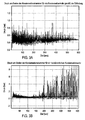
- the dynamic pressure loads are the Condensation chamber walls much lower because the outflow surface from the Outflow nozzle is mostly closed by the coolant, while at the conventional embodiment, the full pipe cross-section is always exposed has been. Tests carried out by the inventors have confirmed that the Comparison of pressure loads on the floor and walls of the condensation chamber significantly reduced to conventional constructions of the condensation pipes.
- the outflow nozzle is through a tube piece is formed, the bottom of which faces the condensation chamber Side longer than that facing away from the bottom of the condensation chamber Side is so that the local mixing zone of steam and water in which when Chugging due to the bladder collapse creates the highest pressure transients the bottom of the condensation chamber is shielded.
- the manifold angle of the manifold is preferably between about 70 ° and about 85 °, preferably about 82 °, so that the lower end of the elbow slants immersed in the coolant in the condensation chamber.
- the essential part of the condensation tube embedded in the wall of the condensation chamber can all that occur in the condensation tube Absorb forces and additional protection in the event of a possible breakage Ensure condensation pipe.
- the Part of very complex holding structures for the conventionally free in the Condensation chamber attached condensation pipes avoided.
- a reactor pressure vessel is centrally located in a closed safety vessel 10 12 arranged.
- a condensation chamber 14 is provided to the side of the reactor pressure vessel 12 arranged.
- the flood basin 16 is towards the interior of the security container 10 open at the top.
- the condensation chamber 14 and the flood basin 16 are each partially with a cooling liquid 20, in particular water, up to a fill level 22 filled.
- the maximum fill level 22 in the flood basin 16 is due to the determined upper end of an overflow pipe 24.
- the overflow pipe 24 connects this Flood basin 16 with the condensation chamber 14 and opens into the cooling liquid 20 of the condensation chamber 14, so that when the maximum is exceeded Level 22, the cooling liquid 20 from the flood basin 16 into the condensation chamber 14 flows out.
- the flood basin 16 is still a flood line 26 connected to the reactor pressure vessel 12 and this in an emergency supply sufficient coolant 20.
- the condensation chamber 14 is largely closed off from the pressure chamber 18. It is only available via one or more condensation pipe 28 the pressure chamber 18 in connection.
- the condensation tube 28 dips into the Cooling liquid 20 in the condensation chamber 14, so that between the Condensation chamber 14 and the pressure chamber 18 no gas exchange takes place.
- the condensation pipe 28 is normally through a water column 30 in Condensation tube 28 closed; only in the event of an accident when the pressure in the pressure chamber 18, steam flows over the condensation tube 28 for condensing into the condensation chamber 14. The exact structure and the Operation of the condensation tube 28 will be explained later with reference to FIG. 2 explained in more detail.
- a building condenser 32 arranged in the left half of Fig. 1 in the upper area of the containment 10 and thus in the upper area of the pressure chamber 18 a building condenser 32 arranged.
- the building condenser 32 is a heat exchanger with heat exchanger tubes equipped and stands with a cooling basin 34 fluidically in connection, the outside of the security container 10 on its lid 36 is arranged.
- the building condenser 32 takes the heat out of it Environment within the containment 10 and passes them to the cooling basin 34 further, causing heat from the containment 10 to the outer Environment can be delivered.
- non-condensable gases such as hydrogen or inert gases such as air or nitrogen
- the non-condensable gases collect in the upper area of the pressure chamber and lead to an increase in the Pressure in the safety container 10.
- a certain pressure in the Pressure chamber 18 can pass the steam with the non-condensable gases the condensation tube 28 the pressure of the water column 30 in the condensation tube 28 overcome and flow into the condensation chamber 24.
- the carried Steam is cooled in the condensation chamber 14 and condensed out while the non-condensable gases remain in the condensation chamber 14.
- the non-condensable gases affect the efficiency of the Building condenser 32 by increasing the heat exchangeability of the building condenser 32 significantly reduce.
- the building condenser 32 can gas significantly less heat per time and Remove surface unit from the steam to the cooling basin 34 than when you are away of the non-condensable gases. Because these non-condensable gases through the condensation pipe 28 from the vicinity of the building condenser 32 can be derived, the building condenser 32 can be designed for saturated steam become. Therefore, it does not need large and specially designed heat exchange surfaces, that in the presence of non-condensable gases would be absolutely necessary to be able to dissipate sufficient heat.
- the Building capacitor 32 can therefore be simpler, more compact and therefore cheaper be designed.
- the condensation tube 28 has an essentially vertical one Main section 28a, at the upper end of an inflow opening 28b inside the pressure chamber 18 is provided. At the bottom of the vertical section 28a of the condensation pipe 28 is followed by an elbow 28c.
- the Elbow 28c is essentially a bent tube section with an elbow angle 28e preferably between approximately 70 ° and 85 °, particularly preferably approximately 82 °. Through this elbow 28c, the condensation pipe 28 projects below the Level of the cooling liquid 20 in the condensation chamber 14 with a slightly sloping down into the coolant.
- An outflow nozzle 28d is provided in the elbow 28c.
- the outflow nozzle is 28d made from a straight piece of pipe in the exemplary embodiment shown, whose length on the bottom of the condensation chamber 14 facing Side is significantly longer than that on the side facing away from the floor.
- condensation tube 28 In contrast to conventional security containers 10 is the condensation tube 28 also not by corresponding holding structures in the condensation chamber held. Instead, it is an essential part of the condensation tube 28, in particular the vertically extending main section 28a and Most of the elbow 28c, embedded in the concrete wall of the condensation chamber. The wall 38 of the condensation chamber 14 thereby takes all in the Condensation pipe occurring forces and offers additional protection in the event of a condensation tube 28 breaking.
- the invention provides a safety container 10 of a nuclear power plant ready, which has a condensation tube that has significantly lower pressure loads to the bottom and walls of the condensation chamber than a conventional one Condensation pipe causes. This will ensure the security of the containment increases and the requirements for the building structure of the containment are getting smaller.
- the configuration of the outflow nozzle is not based on that described above Limited form of a straight pipe section with sides of different lengths.
- the only decisive factor in the design of the outflow nozzle is the outflow effect achieved by the outflow nozzle through the condensation tubes flowing media.
- the condensation tubes from the vertical Main section, the manifold and the exhaust nozzle are both formed in one piece be as well as several separately manufactured and then together tightly connected components exist.
Landscapes
- Physics & Mathematics (AREA)
- Engineering & Computer Science (AREA)
- Plasma & Fusion (AREA)
- General Engineering & Computer Science (AREA)
- High Energy & Nuclear Physics (AREA)
- Structure Of Emergency Protection For Nuclear Reactors (AREA)
Abstract
Description
- Fig.1
- eine stark vereinfachte und schematische Querschnittsanschnitts durch einen Sicherheitsbehälter eines Siedewasserreaktors gemäß der vorliegenden Erfindung;
- Fig. 2
- eine vergrößerte Detailansicht der Kondensationskammer und des Kondensationsrohres des Sicherheitsbehälters von Fig. 1 gemäß der Erfindung;
- Fig. 3A
- eine graphische Darstellung von Messergebnissen der Druckbelastung am Boden der Kondensationskammer bei einem Störfall für ein Kondensationsrohr gemäß der Erfindung; und
- Fig. 3B
- eine graphische Darstellung der Druckbelastung am Boden der Kondensationskammer in einem Störfall für ein herkömmliches Kondensationsrohr.
- 10
- Sicherheitsbehälter
- 12
- Reaktordruckbehälter
- 14
- Kondensationskammer
- 16
- Flutbecken
- 18
- Druckkammer
- 20
- Kühlflüssigkeit
- 22
- Füllstandsniveau
- 24
- Überlaufrohr
- 26
- Flutleitung
- 28
- Kondensationsrohr
- 28a
- vertikaler Hauptabschnitt von 28
- 28b
- Einströmöffnung von 28
- 28c
- Krümmer
- 28d
- Ausströmdüse
- 28e
- Krümmerwinkel
- 30
- Wassersäule
- 32
- Gebäudekondensator
- 34
- Kühlbecken
- 36
- Deckel von 10
- 38
- Betonwand von 14
Claims (5)
- Sicherheitsbehälter (10) einer Kernkraftanlage, mit einer Druckkammer (18), einer Kondensationskammer (14) und einem im wesentlichen vertikal verlaufenden Kondensationsrohr (28), dessen oberes Ende mit der Druckkammer verbunden ist und dessen unteres Ende in eine Kühlflüssigkeit (20) in der Kondensationskammer eintaucht,
dadurch gekennzeichnet, dass das untere Ende des Kondensationsrohres (28) einen Krümmer (28c) und eine Ausströmdüse (28d) aufweist,
wobei der Krümmer (28c) einen Krümmerwinkel (28e) derart aufweist, dass das untere Ende des Krümmers schräg in die Kühlflüssigkeit (20) in der Kondensationskammer (14) eintaucht, und
wobei die Ausströmdüse (28d) eine Ausströmöffnung aufweist, die gegenüber dem Boden der Kondensationskammer (14) im wesentlichen abgeschirmt ist. - Sicherheitsbehälter nach Anspruch 1, bei welchem die Ausströmdüse (28d) des Kondensationsrohres (28) durch ein Rohrstück gebildet ist, dessen dem Boden der Kondensationskammer (14) zugewandte Seite länger als die dem Boden der Kondensationskammer abgewandte Seite ist.
- Sicherheitsbehälter nach Anspruch 1 oder 2, bei welchem der Krümmerwinkel (28e) des Krümmers (28c) des Kondensationsrohres (28) zwischen etwa 70° und etwa 85° beträgt, so dass das untere Ende des Krümmers schräg nach unten geneigt in die Kühlflüssigkeit (20) in der Kondensationskammer (14) eintaucht.
- Sicherheitsbehälter nach Anspruch 3, bei welchem der Krümmerwinkel (28e) des Krümmers (28c) etwa 82° beträgt.
- Sicherheitsbehälter nach einem der Ansprüche 1 bis 4, bei welchem ein wesentlicher Teil des Kondensationsrohres (28) in der Wand (38) der Kondensationskammer (14) eingebettet ist.
Applications Claiming Priority (2)
| Application Number | Priority Date | Filing Date | Title |
|---|---|---|---|
| DE10258354 | 2002-12-12 | ||
| DE10258354A DE10258354B3 (de) | 2002-12-12 | 2002-12-12 | Sicherheitsbehälter einer Kernkraftanlage |
Publications (2)
| Publication Number | Publication Date |
|---|---|
| EP1429343A1 true EP1429343A1 (de) | 2004-06-16 |
| EP1429343B1 EP1429343B1 (de) | 2010-01-06 |
Family
ID=32319089
Family Applications (1)
| Application Number | Title | Priority Date | Filing Date |
|---|---|---|---|
| EP03021849A Expired - Lifetime EP1429343B1 (de) | 2002-12-12 | 2003-09-26 | Sicherheitsbehälter einer Kernkraftanlage |
Country Status (5)
| Country | Link |
|---|---|
| US (1) | US7606344B2 (de) |
| EP (1) | EP1429343B1 (de) |
| JP (1) | JP3992677B2 (de) |
| DE (2) | DE10258354B3 (de) |
| TW (1) | TWI251839B (de) |
Families Citing this family (3)
| Publication number | Priority date | Publication date | Assignee | Title |
|---|---|---|---|---|
| US9984777B2 (en) * | 2007-11-15 | 2018-05-29 | Nuscale Power, Llc | Passive emergency feedwater system |
| CN113029848B (zh) * | 2021-03-03 | 2022-11-25 | 上海交通大学 | 一种测试核电站安全壳内壁面冷凝液回收效率的试验装置 |
| CN115289396B (zh) * | 2022-07-29 | 2024-01-19 | 上海核工程研究设计院股份有限公司 | 一种减轻容器内下插管道破口事故后果的装置及方法 |
Citations (4)
| Publication number | Priority date | Publication date | Assignee | Title |
|---|---|---|---|---|
| DE2303261A1 (de) * | 1973-01-24 | 1974-07-25 | Licentia Gmbh | Kondensationsrohr, insbesondere fuer druckabbausysteme |
| DE2618108A1 (de) * | 1976-04-26 | 1977-11-10 | Interatom | Vorrichtung zum abbauen durch austritt von dampf in einer druckkammer o.dgl. entstandenen drucks |
| JPS5531903A (en) * | 1978-08-29 | 1980-03-06 | Nippon Atomic Ind Group Co | Pressure suppression device of bwr reactor |
| JP2000292578A (ja) * | 1999-03-31 | 2000-10-20 | Toshiba Corp | 格納容器内蒸気凝縮装置 |
Family Cites Families (19)
| Publication number | Priority date | Publication date | Assignee | Title |
|---|---|---|---|---|
| JPS5241149B2 (de) * | 1974-03-16 | 1977-10-17 | ||
| DE2505848A1 (de) * | 1975-02-12 | 1976-09-02 | Kraftwerk Union Ag | Abblaseeinrichtung fuer dampfkraftwerke |
| JPS6018960B2 (ja) * | 1975-09-05 | 1985-05-13 | 株式会社日立製作所 | 原子炉格納容器 |
| DE2809466C3 (de) * | 1978-03-04 | 1986-05-28 | Brown Boveri Reaktor GmbH, 6800 Mannheim | Einrichtung zur Notkühlung eines Dampferzeugers eines Kernkraftwerkes |
| US4305869A (en) * | 1978-07-24 | 1981-12-15 | Monsanto Company | Terpolymers with improved heat distortion resistance |
| DE3525986A1 (de) * | 1985-07-20 | 1987-01-29 | Hochtemperatur Kernkraftwerk | Fluessigkeitsvorlage als rberdruckventil |
| US4948554A (en) * | 1989-01-06 | 1990-08-14 | General Electric Company | Natural circulating passive cooling system for nuclear reactor containment structure |
| DE3910262C1 (de) * | 1989-03-30 | 1990-11-08 | Deutsche Gesellschaft Fuer Wiederaufarbeitung Von Kernbrennstoffen Mbh, 3000 Hannover, De | |
| JPH0718941B2 (ja) * | 1989-05-11 | 1995-03-06 | 株式会社日立製作所 | 原子炉格納容器 |
| CH678371A5 (de) * | 1989-06-14 | 1991-08-30 | Sulzer Ag | |
| JP2528977B2 (ja) * | 1989-11-22 | 1996-08-28 | 株式会社日立製作所 | 原子炉格納容器 |
| US4986956A (en) * | 1989-11-27 | 1991-01-22 | Stone & Webster Engineering Corporation | Passive nuclear power plant containment system |
| JP2793437B2 (ja) * | 1991-07-08 | 1998-09-03 | 株式会社東芝 | 原子炉格納容器 |
| EP0681300A1 (de) * | 1994-05-04 | 1995-11-08 | General Electric Company | Druckabbausystem |
| US5570401A (en) * | 1995-09-22 | 1996-10-29 | General Electric Company | BWR containment configuration having partitioned wetwell airspace |
| DE19653526C1 (de) * | 1996-12-20 | 1998-06-10 | Siemens Ag | Druckhalter mit Sprühvorrichtung |
| DE19809000C1 (de) * | 1998-03-03 | 1999-07-22 | Siemens Ag | Sicherheitsbehälter und Verfahren zum Betrieb eines Kondensators in einer Kernkraftanlage |
| JPH11281786A (ja) * | 1998-03-31 | 1999-10-15 | Toshiba Corp | 原子炉格納容器 |
| KR100366159B1 (ko) * | 1998-08-11 | 2003-01-09 | 미츠비시 쥬고교 가부시키가이샤 | 습식 배연 탈황 장치 |
-
2002
- 2002-12-12 DE DE10258354A patent/DE10258354B3/de not_active Expired - Fee Related
-
2003
- 2003-09-26 EP EP03021849A patent/EP1429343B1/de not_active Expired - Lifetime
- 2003-09-26 DE DE50312314T patent/DE50312314D1/de not_active Expired - Lifetime
- 2003-12-04 US US10/727,753 patent/US7606344B2/en not_active Expired - Fee Related
- 2003-12-08 TW TW092134547A patent/TWI251839B/zh not_active IP Right Cessation
- 2003-12-09 JP JP2003409886A patent/JP3992677B2/ja not_active Expired - Fee Related
Patent Citations (4)
| Publication number | Priority date | Publication date | Assignee | Title |
|---|---|---|---|---|
| DE2303261A1 (de) * | 1973-01-24 | 1974-07-25 | Licentia Gmbh | Kondensationsrohr, insbesondere fuer druckabbausysteme |
| DE2618108A1 (de) * | 1976-04-26 | 1977-11-10 | Interatom | Vorrichtung zum abbauen durch austritt von dampf in einer druckkammer o.dgl. entstandenen drucks |
| JPS5531903A (en) * | 1978-08-29 | 1980-03-06 | Nippon Atomic Ind Group Co | Pressure suppression device of bwr reactor |
| JP2000292578A (ja) * | 1999-03-31 | 2000-10-20 | Toshiba Corp | 格納容器内蒸気凝縮装置 |
Also Published As
| Publication number | Publication date |
|---|---|
| EP1429343B1 (de) | 2010-01-06 |
| US20050135543A1 (en) | 2005-06-23 |
| US7606344B2 (en) | 2009-10-20 |
| TWI251839B (en) | 2006-03-21 |
| DE10258354B3 (de) | 2004-07-29 |
| DE50312314D1 (de) | 2010-02-25 |
| JP2004191377A (ja) | 2004-07-08 |
| JP3992677B2 (ja) | 2007-10-17 |
| TW200414230A (en) | 2004-08-01 |
Similar Documents
| Publication | Publication Date | Title |
|---|---|---|
| EP0563118B1 (de) | Kernrückhaltevorrichtung für kernreaktoranlage und notkühlung bei kernschmelze | |
| DE69503606T2 (de) | Ein system zur passiven wärmeabfuhr aus dem innenraum einer kernreaktorschutzhülle | |
| EP0702835A1 (de) | Einrichtung und verfahren zum auffangen und kühlen von kernschmelze | |
| EP1656679A2 (de) | Kerntechnische anlage und verfahren zur druckentlastung einer kerntechnischen anlage | |
| WO1995001640A1 (de) | Einrichtung zum auffangen und kühlen von kernschmelze | |
| DE2459339C3 (de) | Kühl- und Auffangvorrichtung für den schmelzenden oder geschmolzenen Kern eines Atomkernreaktors | |
| DE2809466C3 (de) | Einrichtung zur Notkühlung eines Dampferzeugers eines Kernkraftwerkes | |
| EP1060475B1 (de) | Sicherheitsbehälter und verfahren zum betrieb eines kondensators in einer kernkraftanlage | |
| DE2809076C2 (de) | Abzug für das wieder umgewälzte Wasser der Sicherheitseinspritz- und Sprühkreise eines Kernreaktors | |
| DE69007327T2 (de) | Primärsicherheitseinschluss mit äusserem Wasserbecken. | |
| EP0141237B1 (de) | Anordnung zur Kühlung einer wärmeerzeugenden Vorrichtung | |
| DE2904201C3 (de) | Abschlämmeinrichtung für einen Wärmetauscher | |
| DE10258354B3 (de) | Sicherheitsbehälter einer Kernkraftanlage | |
| DE1917184A1 (de) | Anlage zur Druckunterdrueckung bei Kernreaktoren | |
| DE2825734C2 (de) | ||
| DE3218190C2 (de) | Tragkonstruktion für Hochbauten | |
| DE2316066C2 (de) | Kernreaktor, insbes. Druckwasserreaktor | |
| EP3915393B1 (de) | Tanksystem zur kühlung einer flüssigkeit mit thermischer schichtung | |
| DE2625542A1 (de) | Reaktoranlage | |
| DE69203276T2 (de) | Druckwasserkernreaktor, der eine Einrichtung zur Entwässerung des Primärkreislaufs mit einem bestimmten Tiefstand mit einer Selbstsicherung aufweist. | |
| DE19527462C1 (de) | Behälter zur Aufnahme und Ausbreitung von Kernschmelze sowie Kernkraftanlage mit einem solchen Behälter | |
| DD300885A5 (de) | Mehrere abscheideabteilungen aufweisender leichtfluessigkeitsabscheider | |
| EP1103491B1 (de) | Verfahren und Vorrichtung zur Beatmung von Tankanlagen | |
| DE10318141B4 (de) | Kerntechnische Anlage mit Überlaufeinrichtung zwischen Flutbecken und Kondensationskammer und Verfahren zum Betrieb einer solchen kerntechnischen Anlage | |
| WO2004093093A2 (de) | Kerntechnische anlage und verfahren zum betrieb einer kerntechnischen anlage |
Legal Events
| Date | Code | Title | Description |
|---|---|---|---|
| PUAI | Public reference made under article 153(3) epc to a published international application that has entered the european phase |
Free format text: ORIGINAL CODE: 0009012 |
|
| AK | Designated contracting states |
Kind code of ref document: A1 Designated state(s): AT BE BG CH CY CZ DE DK EE ES FI FR GB GR HU IE IT LI LU MC NL PT RO SE SI SK TR |
|
| AX | Request for extension of the european patent |
Extension state: AL LT LV MK |
|
| 17P | Request for examination filed |
Effective date: 20041013 |
|
| 17Q | First examination report despatched |
Effective date: 20041109 |
|
| R17P | Request for examination filed (corrected) |
Effective date: 20041013 |
|
| AKX | Designation fees paid |
Designated state(s): DE FI SE |
|
| RBV | Designated contracting states (corrected) |
Designated state(s): DE FI SE |
|
| RAP1 | Party data changed (applicant data changed or rights of an application transferred) |
Owner name: AREVA NP GMBH |
|
| RAP1 | Party data changed (applicant data changed or rights of an application transferred) |
Owner name: AREVA NP GMBH |
|
| GRAP | Despatch of communication of intention to grant a patent |
Free format text: ORIGINAL CODE: EPIDOSNIGR1 |
|
| GRAS | Grant fee paid |
Free format text: ORIGINAL CODE: EPIDOSNIGR3 |
|
| GRAA | (expected) grant |
Free format text: ORIGINAL CODE: 0009210 |
|
| AK | Designated contracting states |
Kind code of ref document: B1 Designated state(s): DE FI SE |
|
| REF | Corresponds to: |
Ref document number: 50312314 Country of ref document: DE Date of ref document: 20100225 Kind code of ref document: P |
|
| REG | Reference to a national code |
Ref country code: SE Ref legal event code: TRGR |
|
| PLBE | No opposition filed within time limit |
Free format text: ORIGINAL CODE: 0009261 |
|
| STAA | Information on the status of an ep patent application or granted ep patent |
Free format text: STATUS: NO OPPOSITION FILED WITHIN TIME LIMIT |
|
| 26N | No opposition filed |
Effective date: 20101007 |
|
| REG | Reference to a national code |
Ref country code: DE Ref legal event code: R082 Ref document number: 50312314 Country of ref document: DE Representative=s name: TERGAU & WALKENHORST PATENTANWAELTE - RECHTSAN, DE |
|
| REG | Reference to a national code |
Ref country code: DE Ref legal event code: R081 Ref document number: 50312314 Country of ref document: DE Owner name: AREVA GMBH, DE Free format text: FORMER OWNER: AREVA NP GMBH, 91052 ERLANGEN, DE Effective date: 20130523 Ref country code: DE Ref legal event code: R082 Ref document number: 50312314 Country of ref document: DE Representative=s name: TERGAU & WALKENHORST PATENTANWAELTE PARTGMBB, DE Effective date: 20130523 Ref country code: DE Ref legal event code: R082 Ref document number: 50312314 Country of ref document: DE Representative=s name: TERGAU & WALKENHORST PATENTANWAELTE - RECHTSAN, DE Effective date: 20130523 |
|
| PGFP | Annual fee paid to national office [announced via postgrant information from national office to epo] |
Ref country code: DE Payment date: 20140923 Year of fee payment: 12 Ref country code: FI Payment date: 20140922 Year of fee payment: 12 |
|
| PGFP | Annual fee paid to national office [announced via postgrant information from national office to epo] |
Ref country code: SE Payment date: 20140923 Year of fee payment: 12 |
|
| REG | Reference to a national code |
Ref country code: DE Ref legal event code: R119 Ref document number: 50312314 Country of ref document: DE |
|
| REG | Reference to a national code |
Ref country code: SE Ref legal event code: EUG |
|
| PG25 | Lapsed in a contracting state [announced via postgrant information from national office to epo] |
Ref country code: FI Free format text: LAPSE BECAUSE OF NON-PAYMENT OF DUE FEES Effective date: 20150926 Ref country code: SE Free format text: LAPSE BECAUSE OF NON-PAYMENT OF DUE FEES Effective date: 20150927 |
|
| PG25 | Lapsed in a contracting state [announced via postgrant information from national office to epo] |
Ref country code: DE Free format text: LAPSE BECAUSE OF NON-PAYMENT OF DUE FEES Effective date: 20160401 |