EP1429336A2 - Aufbewahrungsbehälter für Ton-, Bild- oder Computerplatte - Google Patents
Aufbewahrungsbehälter für Ton-, Bild- oder Computerplatte Download PDFInfo
- Publication number
- EP1429336A2 EP1429336A2 EP03007226A EP03007226A EP1429336A2 EP 1429336 A2 EP1429336 A2 EP 1429336A2 EP 03007226 A EP03007226 A EP 03007226A EP 03007226 A EP03007226 A EP 03007226A EP 1429336 A2 EP1429336 A2 EP 1429336A2
- Authority
- EP
- European Patent Office
- Prior art keywords
- disk
- tabs
- retaining
- riser
- center
- Prior art date
- Legal status (The legal status is an assumption and is not a legal conclusion. Google has not performed a legal analysis and makes no representation as to the accuracy of the status listed.)
- Withdrawn
Links
Images

Classifications
-
- G—PHYSICS
- G11—INFORMATION STORAGE
- G11B—INFORMATION STORAGE BASED ON RELATIVE MOVEMENT BETWEEN RECORD CARRIER AND TRANSDUCER
- G11B33/00—Constructional parts, details or accessories not provided for in the other groups of this subclass
- G11B33/02—Cabinets; Cases; Stands; Disposition of apparatus therein or thereon
- G11B33/04—Cabinets; Cases; Stands; Disposition of apparatus therein or thereon modified to store record carriers
- G11B33/0405—Cabinets; Cases; Stands; Disposition of apparatus therein or thereon modified to store record carriers for storing discs
- G11B33/0411—Single disc boxes
- G11B33/0422—Single disc boxes for discs without cartridge
- G11B33/0427—Single disc boxes for discs without cartridge comprising centre hole locking means
Definitions
- the present invention relates to a diskette storage box for one or more audio, audio-visual or computer media disks, including CDs, CD-ROMs, CD-RWs, DVDs and the like.
- Compact disks that store music (e.g., CD), data (e.g., CD-ROM, CD-R, CD-RW) and video (e.g., DVD) are quite common and are in wide-spread usage.
- These types of disks commonly are stored in plastic storage boxes known as jewel boxes.
- these boxes include some sort of central retaining mechanism that holds a disk by utilizing the disk's center hole. Examples of various types of boxes are shown in U.S. Patent No. 6,398,022, U.S. Patent No. 6,419,084, U.S. Patent No. 5,829,582, U.S. Patent No. Des. 438,418, U.S. Patent No. Des. 439,786, U.S. Patent No. 5,944,181, U.S. Patent No. 5,788,068, U.S. Patent No. 5,526,926, U.S. Patent No. 5,685,427 and U.S. Patent No. 5,887,713.
- the present invention is intended to overcome some or all of these problems, and to provide a disk storage box which allows for insertion and removal of the disks in a quick, easy, efficient and/or convenient manner.
- a box for retaining a disk having a center hole includes a front cover, and a rear cover adapted to retain a disk having a center hole, the front and rear covers being, preferably rotatably, attached so that the box can be opened and closed by movement of the front cover away and toward the rear cover.
- the rear cover includes a disk accommodating surface, preferably in the form of, and referred to below as, a flat rear surface and a disk retaining mechanism integral with the flat rear surface for retaining the disk.
- the disk retaining mechanism includes a plurality of first surfaces extending upward from the flat rear surface, each of the plurality of first surfaces extending inwards towards a center position of the disk retaining mechanism, the center position being aligned with a center of the disk when retained by the disk retaining mechanism.
- the disk retaining mechanism further includes plural riser tabs, and each riser tab is attached to and extends upwards from a respective one of the plurality of first surfaces.
- the disk retaining mechanism also includes plural retaining tabs, and each retaining tab is attached to a top of a respective riser tab.
- each retaining tab extends outwardly away from the center position, and the retaining tabs are sized and positioned relative to the rear cover so as to retain the disk by being disposed immediately above the inner periphery of the disk.
- the disk retaining mechanism includes a riser tabs limiting device that is coupled to the plurality of riser tabs for limiting an amount of movement of those riser tabs.
- the riser tabs limiting device or means is a (center) release button that is attached to each of the riser tabs.
- the center release button is adapted to move the retaining tabs toward the center position of the disk retaining mechanism when the center release button is depressed so that a retained disk is released upon the depression of the center release button.
- the center release button is attached to the bottom of each of the riser tabs and the center release button is sized to limit inward movement of each of the riser tabs upon depression of the center release button.
- the disk retaining mechanism preferably includes at least three, in particular four, first surfaces, at least three, in particular four, riser tabs and at least three, in particular four, retaining tabs, each of the first surfaces, riser tabs and retaining tabs are disposed concentrically around the center position so that, when there are four such tabs, the four riser tabs form a square shaped opening with a center aligned with the center position.
- each of the four first surfaces preferably includes a respective protruding surface element and an intermediate surface element, preferably a substantially horizontal surface element (that is, substantially parallel with the plane of the rear surface of the rear cover) attached and integral to the protruding surface so that an inner circular portion of the retained disk immediately adjacent to its center hole rests on each of the intermediate, preferably horizontal surface elements of the four first surfaces.
- the disk retaining mechanism further includes at least three, in particular four, second surfaces disposed concentrically around the center position between a respective pair of adjacent first surfaces and extending upward from the flat rear surface of the rear cover towards the center position of the disk retaining mechanism.
- Each of the second surfaces is integral with a respective intermediate surface element, preferably a substantially horizontal surface, disposed between a respective pair of intermediate surface elements of the first surfaces so that substantially the entire inner circular portion of the retained disk rests on the intermediate, preferably substantially horizontal surface elements of the four first surfaces and the intermediate, preferably substantially horizontal surface elements integral with the second surfaces.
- the intermediate surface elements of the first surfaces and integral with the second surfaces lie on a common surface (of revolution).
- the box includes a second disk retaining mechanism for retaining a second disk.
- all of the components of the disk retaining means, and preferably the back cover, are integral, that is formed in one piece.
- Disk storage box 10 is designed to store a compact disk, such as audio CDs, video disks known as DVDs, or computer disks, such as CD-ROM, CD-R and CD-RW disks.
- a compact disk such as audio CDs, video disks known as DVDs
- computer disks such as CD-ROM, CD-R and CD-RW disks.
- other types of disks may be stored and disks of various sizes may be stored, including so-called mini disks, as well as other types of disks not currently in common usage.
- Box 10 includes a front cover (or lid) 12, a rear cover (or base) 14, and a spine 16.
- Spine 16 is attached to both front and rear covers 12 and 14 and operates as a hinge so that the box may be closed in a manner well known in the art.
- Spine 16 operates in a manner well known in the art and thus further description thereof is omitted herein.
- Front cover 12 includes a pair of clips 18 that serve to hold a booklet or other thin item within the box, and such is well known in the art.
- the rear cover includes a retaining ring 20 that is integral with and extends upwards from rear cover 14.
- Retaining ring 20 includes a circular, ring-shaped ridge 22 that extends alongside its inner circumference and ridge 22 is sized accordingly so that the outer, circumferential edge of a compact disk rests fully on ridge 22 upon insertion of the disk in storage box 10.
- the surface of ridge 22 on which a disk rests is slightly above the surface 24 of rear cover 14 so that a small space exists between that portion of the or a face of the disk (which may be a surface which contains information) and the rear cover's surface 24.
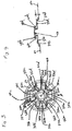
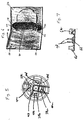
- rear surface 24 includes a disk retaining mechanism 30.
- Disk retaining mechanism 30 is described with reference to Figs. 3 - 4 of the drawings.
- disk retaining mechanism includes a number of components and, in the preferred embodiment, disk retaining mechanism including all of its components are formed integral with one another.
- Each surface 32 (i.e., 32a, 32b, 32c and 32d) ends with a respective, horizontal comer surface (or surface element) 33 (i.e., 33a, 33b, 33c and 33d) so that surfaces 33a, 33b, 33c and 33d extend along a plane B (see Fig. 4).
- Fig. 4 which is a cross-sectional, side view of disk retaining mechanism 30, rear surface 24 extends along a plane A with plane B extending above and parallel to plane A.
- mechanism 30 includes four (4) rectangular-shaped protrusions 34a, 34b, 34c and 34d that extend both inwardly and upwardly, similar to how surfaces 32a, 32b, 32c and 34d extend.
- protrusions 34a, 34b, 34c and 34d are positioned around center point C at 0, 90, 180 and 270 degrees, respectively, with respect to position P.
- the respective end of each protrusion 34a, 34b, 34c and 34d is integral with a respective horizontal surface (or surface element) 35a, 35b, 35c and 35d (similar in design to surface sets 32a-32d and 33a-33b).
- Surfaces 35a-35d are horizontally disposed and extend along plane B.
- An opening 36 (36a-36d) in the disk structure may be included.
- Each riser tab 38 includes, near its top, a respective retaining/lifting tab 40 (i.e., 40a, 40b, 40c and 40d shown in Fig. 3).
- Each retaining/lifting tab 40 is integral with and extends outwards (horizontally) from a respective riser table.
- Tabs 40b and 40d are also shown in Fig. 4.
- the retaining/lifting tabs 40a, 40b, 40c and 40d serve to retain a disk after the disk's insertion into the storage box of the present invention, and also serve to assist with the lifting of the disk during its removal.
- each of the four riser tabs 38a-38d are connected to (or integral with) a rectangular-shaped, center release button 42.
- the interconnection between release button 42 and riser tabs 38a-38d is best shown in Fig. 4, which shows the interconnection between riser tabs 38b and 38d with release button 42.
- Release button 42 may have a hollow interior and open bottom as shown in Fig. 4.
- a disk to be inserted is placed immediately over surface 24 of rear cover 14 so that the disk is in alignment with the circular shape of retaining ring 20 (see Fig. 2).
- the disk is placed down so that its inner, circular edge is resting directly on the four retaining/lifting tabs 40a, 40b, 40c and 40d.
- the disk is urged slightly downward.
- roughly equal force is applied to opposite portions of the top surface of the disk.
- retaining/lifting tabs 40a-40d along with vertical riser tabs 38a, 38b, 38c and 38d likewise are urged downwards.
- each of the protrusions 34a, 34b, 34c and 34d is urged downward, which causes each of the protrusions 34a-34d to pivot (slightly) about its respective other end, which is integral with the rear cover's surface 24.
- each of the riser tabs 38a-38d is closer to center release button 42.
- each of the retaining/lifting tabs 40a-40d are moved closer to center release button 42 (and center point C).
- the relative lengths of the components are designed so that when retaining/lifting tabs 40a-40d are urged downward (by depressing a disk thereon), the retaining/lifting tabs 40a-40d move inward (as a result of the above-discussed movement) sufficiently so that the retaining/lifting tabs 40a-40d are able to pass through the disk's center hole as the disk is urged downwards.
- the retaining/lifting tabs 40a-40d have a sloped upper edge, as best shown in Fig. 4, to further facilitate their downward and inward movement towards center point C as the disk is urged downwards.
- each of the riser tabs 38a-38d are attached at their respective lower, inner ends to center release button 42, as discussed above and partially shown in Fig. 4, such interconnection amongst the riser tabs and button 42 provides additional upward bias on risers tabs 38a-38d to further facilitate locking of the disk by retaining/lifting tabs 40a-40d.
- center release button 42 is depressed which in turn forces the attached riser tabs 38a-38d downward.
- Riser tabs 38a-38d move closer to center point C to the positions shown in Fig. 5, in a manner similar to that described above during insertion of the disk.
- retaining/lifting tabs 40a-40d likewise move inward and downwards and, during such movement, retaining/lifting tabs 40a-40d pass downward through the disk's center hole thereby releasing the disk.
- horizontal surfaces 33a-33d may urge the disk upwardly relative to horizontal surfaces 35a-35d, so as to facilitate lifting the disk relative to the retaining/lifting tabs 40, and encourage them further to pass down through the disk's center hole, and to disengage from the upper surface of the disk.
- center release button 42 prevents riser tabs 38a-38d from being pushed down too far to the point where the various components are undesirably weakened or broken.
- the center release button 42 provide stability amongst all of the movement components of the present invention and prevents movement of the various parts beyond predetermined positions. Further, and in accordance with the present invention, the rear cover along with all of the components of the disk retaining mechanism are fully integral with one another. Thus, if the box of any of its components are damaged, those broken components or the box as a whole is prevented from falling apart. This, in turn, greatly enhances the safety standard of the design as compared to prior art designs.
- Fig. 6 shows another disk storage box 60 embodying the present invention.
- disk storage box 60 includes all of the components shown in the previously discussed embodiment. These include in a front cover (or lid) 62, a rear cover (or base) 64, a spine 66, and a pair of clips 68, all that operate in the manner previously described.
- Box 60 further includes a second disk holder extension 70 (“second disk holder") that is attached to spine 66.
- second disk holder extension 70 (“second disk holder") that is attached to spine 66.
- spine 66 include two pairs of holders 72 (only one pair shown in Fig. 7).
- Each pair of holders 72 receives and holds the second disk holder 70 by grip apertures 74 with second disk holder 70 (apertures 74 shown in Fig. 6).
- second disk holder 70 includes a retaining ring 78 and a disk retaining mechanism 80 that operate in the same manner that the retainer ring and disk retaining mechanism of the previously discussed embodiment operate. Thus further description thereof is omitted herein.
- surfaces 32a, 32b, 32c and 32d shown in Fig. 3 are described as extending upwardly as well as inwardly toward center point C. These surfaces, along with attached surfaces 33a-33d, however do not necessarily need to extend upwardly but may extend from rear surface 24 (Fig. 2) along the same plane (i.e., plane A - see Fig. 4). Still further, surfaces 34a-34d and attached surfaces 35a-35d (see Fig. 3) may represent single flat surfaces that together extend upward from rear surface 24.
Landscapes
- Packaging For Recording Disks (AREA)
Applications Claiming Priority (2)
| Application Number | Priority Date | Filing Date | Title |
|---|---|---|---|
| US316817 | 2002-12-11 | ||
| US10/316,817 US6726008B1 (en) | 2002-12-11 | 2002-12-11 | Box for storing audio-visual or computer media disk |
Publications (2)
| Publication Number | Publication Date |
|---|---|
| EP1429336A2 true EP1429336A2 (de) | 2004-06-16 |
| EP1429336A3 EP1429336A3 (de) | 2006-04-05 |
Family
ID=32107708
Family Applications (1)
| Application Number | Title | Priority Date | Filing Date |
|---|---|---|---|
| EP03007226A Withdrawn EP1429336A3 (de) | 2002-12-11 | 2003-03-31 | Aufbewahrungsbehälter für Ton-, Bild- oder Computerplatte |
Country Status (2)
| Country | Link |
|---|---|
| US (1) | US6726008B1 (de) |
| EP (1) | EP1429336A3 (de) |
Families Citing this family (8)
| Publication number | Priority date | Publication date | Assignee | Title |
|---|---|---|---|---|
| USD508813S1 (en) * | 2002-05-31 | 2005-08-30 | Nexpak Corporation | Low profile disc storage container |
| US20040144662A1 (en) * | 2003-01-24 | 2004-07-29 | Bolognia David L. | Insertable hinged tray for a multiple disc storage container |
| US7108129B2 (en) * | 2003-10-10 | 2006-09-19 | Enxnet, Inc. | Optical disk storage case with blocking tongue |
| EP1759391A1 (de) * | 2004-05-13 | 2007-03-07 | Dualbox Limited | Haltevorrichtung für einen plattenförmigen artikel |
| USD558191S1 (en) | 2004-06-09 | 2007-12-25 | Enxnet, Inc. | Antenna for a storage disc |
| US20090223842A1 (en) * | 2005-06-28 | 2009-09-10 | Frederic Lapointe | Archival data disc storage case |
| US20070138039A1 (en) * | 2005-10-04 | 2007-06-21 | Kevin Kirtz | Media storage container and two-disc hub |
| US20070102311A1 (en) * | 2005-10-08 | 2007-05-10 | Kevin Kirtz | Media storage container with media cartridge page |
Family Cites Families (17)
| Publication number | Priority date | Publication date | Assignee | Title |
|---|---|---|---|---|
| EP0648369B1 (de) | 1993-04-29 | 1998-07-29 | Deja-Accessoires GmbH | Aufbewahrungskassette für cd-platten |
| GB2291640B (en) | 1994-11-03 | 1996-07-24 | Dubois Plc | Apparatus for holding a compact disk |
| US5887713A (en) | 1995-10-26 | 1999-03-30 | Ultrapac, Inc. | Holder for compact discs |
| DE19605336A1 (de) * | 1996-02-14 | 1997-08-21 | Polygram Manufacturing & Distr | Gehäuse zur Aufnahme von plattenförmigen Informationsträgern |
| US5685427A (en) | 1996-05-03 | 1997-11-11 | Ultrapac, Inc. | Holder for removably supporting a compact disk |
| US5829582A (en) | 1997-03-24 | 1998-11-03 | Ippolito; Peter M. | Laser disk holder with one touch disk demounting |
| US6196384B1 (en) * | 1998-04-01 | 2001-03-06 | Alpha Enterprises, Inc. | Storage container for recorded media |
| US5944181A (en) | 1998-09-09 | 1999-08-31 | Finest Industrial Co., Ltd. | Disk protective enclosure |
| ES1045155Y (es) * | 2000-02-09 | 2001-07-01 | Magnetic Imatge Sa | Estuche para discos compactos, discos de video digital y similares con encajamiento escamoteado de bandejas supletorias. |
| US6401920B2 (en) * | 2000-04-21 | 2002-06-11 | Agi Inc. | Multiple disc package with locking and tamper-evident push button |
| USD438418S1 (en) | 2000-06-02 | 2001-03-06 | Nexpak Corporation | Storage container for disc-shaped item of recorded media |
| USD439786S1 (en) | 2000-06-02 | 2001-04-03 | Nexpak Corporation | Storage container for disc-shaped item of recorded media |
| US6427833B1 (en) * | 2000-09-28 | 2002-08-06 | Dragon Plan Limited | Data disc storage case |
| US6398022B1 (en) | 2000-11-07 | 2002-06-04 | Cheong Wing Electric, Ltd. | Digital video disk holder |
| JP3701880B2 (ja) * | 2001-05-01 | 2005-10-05 | 実 田島 | ディスク保持装置 |
| US6419084B1 (en) | 2001-05-25 | 2002-07-16 | Codax Technologies, Inc. | Thin compact disk holder |
| US6547068B2 (en) * | 2001-07-23 | 2003-04-15 | Yuk Lung Chu | Single push-button type storage case for compact discs |
-
2002
- 2002-12-11 US US10/316,817 patent/US6726008B1/en not_active Expired - Fee Related
-
2003
- 2003-03-31 EP EP03007226A patent/EP1429336A3/de not_active Withdrawn
Also Published As
| Publication number | Publication date |
|---|---|
| US6726008B1 (en) | 2004-04-27 |
| EP1429336A3 (de) | 2006-04-05 |
Similar Documents
| Publication | Publication Date | Title |
|---|---|---|
| US5996788A (en) | Storage container for recorded media | |
| US5894924A (en) | Alternative CD-ROM/DVD packaging device | |
| US6789667B2 (en) | Storage container for recorded media | |
| US7431154B2 (en) | Security storage container | |
| US20050173273A1 (en) | Storage container for recorded media | |
| EP1156972A4 (de) | Speichervorrichtung für aufzeichnungsträger | |
| US6364108B1 (en) | Box for packaging or storing DVDs CDs and/or VCDs | |
| US5785172A (en) | Double rosette for compact disc container | |
| US6293396B1 (en) | Container for disk | |
| EP1429336A2 (de) | Aufbewahrungsbehälter für Ton-, Bild- oder Computerplatte | |
| KR20040028764A (ko) | 박형 콤팩트 디스크 홀더 | |
| JP2008502543A (ja) | 傾斜してストックされるデジタルディスクのためのパッケージ体 | |
| JP2004043019A (ja) | ディスク保存容器 | |
| US20070039958A1 (en) | Drink cup lid with disc carrier | |
| JP3814121B2 (ja) | 光ディスクの収納容器 | |
| US7398878B2 (en) | Case for disc-shaped recording medium with function of preventing dropout of holder | |
| KR200284053Y1 (ko) | 디스크 보관 케이스 | |
| US20060131191A1 (en) | Media storage disc case | |
| US20040163974A1 (en) | Optical disk storage case | |
| JP3306036B2 (ja) | 記録媒体用ディスクの収納ケース | |
| KR19990017095U (ko) | 디스크 보관장치 | |
| KR19990017096U (ko) | 디스크 보관장치 | |
| JP2007532425A (ja) | データディスク受け取り用保存ケース | |
| JP3814109B2 (ja) | ディスク収納容器 | |
| JP3659118B2 (ja) | ディスク収納ケース |
Legal Events
| Date | Code | Title | Description |
|---|---|---|---|
| PUAI | Public reference made under article 153(3) epc to a published international application that has entered the european phase |
Free format text: ORIGINAL CODE: 0009012 |
|
| 17P | Request for examination filed |
Effective date: 20030602 |
|
| AK | Designated contracting states |
Kind code of ref document: A2 Designated state(s): AT BE BG CH CY CZ DE DK EE ES FI FR GB GR HU IE IT LI LU MC NL PT RO SE SI SK TR |
|
| AX | Request for extension of the european patent |
Extension state: AL LT LV MK |
|
| PUAL | Search report despatched |
Free format text: ORIGINAL CODE: 0009013 |
|
| AK | Designated contracting states |
Kind code of ref document: A3 Designated state(s): AT BE BG CH CY CZ DE DK EE ES FI FR GB GR HU IE IT LI LU MC NL PT RO SE SI SK TR |
|
| AX | Request for extension of the european patent |
Extension state: AL LT LV MK |
|
| AKX | Designation fees paid |
Designated state(s): AT BE BG CH CY CZ DE DK EE ES FI FR GB GR HU IE IT LI LU MC NL PT RO SE SI SK TR |
|
| STAA | Information on the status of an ep patent application or granted ep patent |
Free format text: STATUS: THE APPLICATION IS DEEMED TO BE WITHDRAWN |
|
| 18D | Application deemed to be withdrawn |
Effective date: 20061003 |