EP1429079A2 - Gargerät mit einer Schaltuhr sowie Schaltuhr - Google Patents
Gargerät mit einer Schaltuhr sowie Schaltuhr Download PDFInfo
- Publication number
- EP1429079A2 EP1429079A2 EP03027822A EP03027822A EP1429079A2 EP 1429079 A2 EP1429079 A2 EP 1429079A2 EP 03027822 A EP03027822 A EP 03027822A EP 03027822 A EP03027822 A EP 03027822A EP 1429079 A2 EP1429079 A2 EP 1429079A2
- Authority
- EP
- European Patent Office
- Prior art keywords
- cooking
- time
- timer
- appliance according
- cooking time
- Prior art date
- Legal status (The legal status is an assumption and is not a legal conclusion. Google has not performed a legal analysis and makes no representation as to the accuracy of the status listed.)
- Withdrawn
Links
- 238000010411 cooking Methods 0.000 title claims abstract description 122
- 238000000034 method Methods 0.000 claims abstract description 19
- 238000010586 diagram Methods 0.000 description 4
- 244000144980 herd Species 0.000 description 3
- 238000012544 monitoring process Methods 0.000 description 3
- 238000010438 heat treatment Methods 0.000 description 2
- 235000015278 beef Nutrition 0.000 description 1
- 235000013305 food Nutrition 0.000 description 1
- 230000003287 optical effect Effects 0.000 description 1
- 238000004886 process control Methods 0.000 description 1
- 230000001105 regulatory effect Effects 0.000 description 1
Images
Classifications
-
- G—PHYSICS
- G04—HOROLOGY
- G04G—ELECTRONIC TIME-PIECES
- G04G15/00—Time-pieces comprising means to be operated at preselected times or after preselected time intervals
- G04G15/006—Time-pieces comprising means to be operated at preselected times or after preselected time intervals for operating at a number of different times
-
- F—MECHANICAL ENGINEERING; LIGHTING; HEATING; WEAPONS; BLASTING
- F24—HEATING; RANGES; VENTILATING
- F24C—DOMESTIC STOVES OR RANGES ; DETAILS OF DOMESTIC STOVES OR RANGES, OF GENERAL APPLICATION
- F24C7/00—Stoves or ranges heated by electric energy
- F24C7/08—Arrangement or mounting of control or safety devices
- F24C7/082—Arrangement or mounting of control or safety devices on ranges, e.g. control panels, illumination
Definitions
- the present invention relates to a cooking device with a timer and a timer for Monitoring a cooking process. After the end of a cooking time, the cooking device will controlled accordingly and / or the end of the cooking time displayed.
- a generic time switch is known, which is a Device for regulating and monitoring baking and cooking processes, in the present case in the context of time and temperature.
- the user can use the timer Specifications regarding the temperature control and the timing of the baking or roasting Do the cooking process.
- the object of the present invention is a cooking device with a timer and to provide a timer with which a reliable monitoring of a Cooking process is enabled.
- the object of the invention is by a cooking device with the features of Claim 1 and solved by a timer according to claim 9.
- the time switch is a Assigned to the display device that starts after the end of the cooking time displays. A user can use it to keep track of information since the end of the cooking time received past period.
- the display device can give the user one end display the time that a cooking program has started.
- the display device according to the At the end of the cooking time, the size of the originally set cooking time Show. From this you can easily add the one that has passed since the start of the cooking time Determine total time.
- the total time is particularly easy to determine if the time that starts after the end of the cooking time to the originally set one Cooking time is counted and displayed.
- the display device of the time switch also shows the timing at the end of the cooking time. This gives the user information about the still remaining cooking time until the end.
- the timer can advantageously have a signal generator. This creates after the end the cooking time a signal that alerts the user to the end of the cooking time points.
- the cooking device can have a temperature sensor for detecting a Operating temperature, e.g. a cooking temperature.
- a Operating temperature e.g. a cooking temperature.
- the start of the Cooking time only take place when a predetermined cooking temperature is reached. This is ensures that the cooking time is only started when there is effective cooking starts.
- the time switch advantageously starts after a heating-up period in Cooking appliance to run.
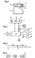
- FIG. 1 shows a stove with an oven 1 and a hob 3 arranged thereon.
- a front control panel 5 of the cooker carries control knobs for the hotplates of the hob 3 and for the oven 1.
- the control panel 5 has a function display 9 known from the prior art with the function switches 11, 13, 15 and 17.
- a selector switch 11 a user can activate one of the hotplates of the hob 3 or the oven 1. If the user activates the oven 1, he can select a cooking program from a number of stored cooking programs via the cooking program switch 13. Each saved cooking program specifies both a cooking time or cooking time interval ⁇ t G and a cooking temperature curve for a cooking process. If the user selects a manual mode of operation, he can manually set the cooking time interval ⁇ t G and / or the cooking temperature curve for the cooking process by means of the temperature switch 15 and the cooking time switch 17.
- the function display 9 is enlarged in FIG. 2 with an associated electronic one Control device 23 and a timer 25 in a highly schematic block diagram shown.
- the electronic control device 23 and the timer 25 are mutually with each other in signal connection.
- the cooking time switch 17 is via a first signal line 27 with the timer 25 in connection.
- the selector switch 11, the cooking program switch 13 and the temperature switch 15 are connected to the electronic via second control lines 28 Control device 23 in connection.
- the electronic Process control device 23 for control purposes actual values of a cooking process.
- the Actual values of the cooking process are recorded by means of a number of sensors in the cooking device and passed to the electronic control device 23.
- In Figure 2 is an example Temperature sensor 29 for detecting a cooking temperature in the cooking space of the oven 1 shown.
- Output lines 31 of the control device 23 conduct control signals Heating devices of the oven 1 or the hob 3.
- both the electronic control device 23 and the time switch 25 are connected to the function display 9.
- the function display 9 has a program display 33 for displaying a cooking program selected by means of the selector switch 11. In FIG. 2, the "beef roast" cooking program is selected. A corresponding display symbol is shown in the program display 33.
- Another display 35 serves as a time display. For example, a cooking time interval .DELTA.t G set manually by means of the cooking time switch 17 can be displayed.
- a temperature display 37 shows the cooking temperature during a cooking process.
- a user To set an automatic cooking program control, a user first activates the oven 1 using the selector switch 11. The user can then use the cooking program switch 13 to select one of the cooking programs stored in the electronic control device 23.
- the cooking temperature curve and the cooking time interval ⁇ t G during the cooking process are defined in the selected cooking program.
- the timer 25 automatically receives a specification for the cooking time interval ⁇ t G from the electronic control device 23.
- the time switch monitors the timing of the specified cooking time interval ⁇ t G.
- the time course of the predetermined cooking time interval ⁇ t G is shown in the time display 35 of the function display 9.
- the program display 33 shows the selected cooking program and the temperature display 37 shows the current cooking temperature.
- the timer 25 sends a corresponding signal to the control device 23, which then ends the cooking process.
- the cooking time interval ⁇ t G only starts when the temperature sensor 29 reaches a predetermined cooking temperature in the cooking space.
- the time course of the cooking time interval ⁇ t G is displayed in the time display 35 until its end time t 1 .
- the control device 23 ends the cooking process and a signal generator 26 of the timer 25 generates an optical and / or acoustic alarm signal.
- the timer 25 continues after the end time t 1 of the cooking process.
- the time ⁇ t A starting after the end of the cooking process is shown in the time display 35.
- the time display 35 shows both the time elapsed from the cooking time interval ⁇ t G to its end and the time ⁇ t A that then starts.
- the time display 35 begins at the time t 0 with the value of the originally set cooking time interval and runs down to zero in the manner of a countdown, ie until the end time t 1 of the cooking time interval ⁇ t G.
- the time display 35 jumps again to the value of the originally set cooking time interval.
- the time ⁇ t A that then starts is counted to the value of the originally set cooking time interval after the end time t 1 of the cooking time interval.
- the time display 35 thus informs the user after the end of the cooking time interval, ie after the end of the cooking process, of how long a food has been in the cooking space.
- the user can also specify the cooking time interval ⁇ t G manually using the cooking time switch 17.
- the cooking time interval ⁇ t G runs independently of the electronic control device 23.
- the signal generator 26 At the end of the cooking time interval ⁇ t G , the signal generator 26 generates a corresponding alarm signal.
- the timer 25 has the cooking time switch 17 for the manual input of the cooking time interval ⁇ t G.
- the time switch 25 is connected to the time display 35 via the signal line 27.
- the signal generator 26 generates At the end of the cooking time interval, an alarm signal informing the user of the end of the cooking process.
Landscapes
- Engineering & Computer Science (AREA)
- Physics & Mathematics (AREA)
- General Physics & Mathematics (AREA)
- Chemical & Material Sciences (AREA)
- Combustion & Propulsion (AREA)
- Mechanical Engineering (AREA)
- General Engineering & Computer Science (AREA)
- Electric Ovens (AREA)
- Cookers (AREA)
Abstract
Description
- Figur 1
- in einer Vorderansicht einen Herd gemäß dem ersten Ausführungsbeispiel;
- Figur 2
- ein stark schematisiertes Blockschaltbild des Herdes mit einer hervorgehobenen Funktionsanzeige;
- Figur 3
- ein Zeitablaufdiagramm zur Erläuterung der Funktionsweise einer Schaltuhr des Herdes; und
- Figur 4
- gemäß dem zweiten Ausführungsbeispiel eine Schaltuhr für ein Gargerät.
Claims (9)
- Gargerät mit einer Schaltuhr (25), die zur Steuerung eines Garvorganges den zeitlichen Ablauf einer Garzeitdauer (ΔtG) überwacht und nach dem Ende (t1) der Garzeitdauer (ΔtG) das Gargerät entsprechend steuert und/oder das Ende (t1) der Garzeitdauer (ΔtG) anzeigt, dadurch gekennzeichnet, dass der Schaltuhr (25) eine Anzeigeeinrichtung (9) zugeordnet ist, die eine nach dem Ende (t1) der Garzeitdauer (ΔtG) startende Zeit (ΔtA) anzeigt.
- Gargerät nach Anspruch 1, dadurch gekennzeichnet, dass die Anzeigeeinrichtung (9) der Schaltuhr (25) nach dem Ende (t1) der Garzeitdauer (ΔtG) zusätzlich die Größe der ursprünglich eingestellten Garzeitdauer anzeigt.
- Gargerät nach einem der Ansprüche 1 oder 2, dadurch gekennzeichnet, dass die Anzeigeeinrichtung (9) der Schaltuhr (25) die nach dem Ende (t1) der Garzeitdauer startende Zeit (ΔtA) auf die ursprünglich eingestellte Garzeitdauer zählt.
- Gargerät nach einem der vorhergehenden Ansprüche, dadurch gekennzeichnet, dass die Anzeigeeinrichtung (9) der Schaltuhr (25) den zeitlichen Ablauf bis zum Ende (t1) der Garzeitdauer (ΔtG) anzeigt.
- Gargerät nach einem der vorhergehenden Ansprüche, dadurch gekennzeichnet, dass die Schaltuhr (25) einen Signalgeber (26) aufweist, der nach dem Ende (t1) der Garzeitdauer (ΔtG) ein Alarmsignal erzeugt.
- Gargerät nach einem der vorhergehenden Ansprüche, dadurch gekennzeichnet, dass der Ablauf der Garzeitdauer (ΔtG) erst bei Erreichen einer vorbestimmten Betriebstemperatur im Gargerät startet.
- Gargerät nach einem der vorhergehenden Ansprüche, dadurch gekennzeichnet, dass eine Einstellung der Garzeitdauer (ΔtG) manuell durch eine Bedienperson erfolgt.
- Gargerät nach einem der Ansprüche 1 bis 6, dadurch gekennzeichnet, dass eine Einstellung der Garzeitdauer (ΔtG) mittels einer elektronischen Steuereinrichtung (23) erfolgt.
- Schaltuhr für ein Gargerät nach einem der vorhergehenden Ansprüche.
Priority Applications (1)
| Application Number | Priority Date | Filing Date | Title |
|---|---|---|---|
| EP03027822A EP1429079A3 (de) | 2002-12-12 | 2003-12-03 | Gargerät mit einer Schaltuhr sowie Schaltuhr |
Applications Claiming Priority (3)
| Application Number | Priority Date | Filing Date | Title |
|---|---|---|---|
| EP02360344 | 2002-12-12 | ||
| EP02360344 | 2002-12-12 | ||
| EP03027822A EP1429079A3 (de) | 2002-12-12 | 2003-12-03 | Gargerät mit einer Schaltuhr sowie Schaltuhr |
Publications (2)
| Publication Number | Publication Date |
|---|---|
| EP1429079A2 true EP1429079A2 (de) | 2004-06-16 |
| EP1429079A3 EP1429079A3 (de) | 2010-11-17 |
Family
ID=32327864
Family Applications (1)
| Application Number | Title | Priority Date | Filing Date |
|---|---|---|---|
| EP03027822A Withdrawn EP1429079A3 (de) | 2002-12-12 | 2003-12-03 | Gargerät mit einer Schaltuhr sowie Schaltuhr |
Country Status (1)
| Country | Link |
|---|---|
| EP (1) | EP1429079A3 (de) |
Family Cites Families (2)
| Publication number | Priority date | Publication date | Assignee | Title |
|---|---|---|---|---|
| DE9400564U1 (de) * | 1994-01-14 | 1994-03-03 | Wiesheu Gmbh | Vorrichtung zur Wärmebehandlung von Lebensmitteln |
| DE4435931C2 (de) * | 1994-10-07 | 1998-06-04 | Convotherm Elektrogeraete | Bedienungseinrichtung für ein Gargerät |
-
2003
- 2003-12-03 EP EP03027822A patent/EP1429079A3/de not_active Withdrawn
Non-Patent Citations (1)
| Title |
|---|
| BRAAS JÜRGEN: "KÜCHENLEITTECHNIK, ENERGIEOPTIMIERUNG UND HACCP-KONTROLLE", 27 February 2001 (2001-02-27), pages 1 - 21, XP002557536, Retrieved from the Internet <URL:http://www.innos.de> * |
Also Published As
| Publication number | Publication date |
|---|---|
| EP1429079A3 (de) | 2010-11-17 |
Similar Documents
| Publication | Publication Date | Title |
|---|---|---|
| DE69705088T2 (de) | Gasgerät zum Erhitzen und/oder zum Kochen von Nahrungsmitteln und dergleichen | |
| DE69403351T2 (de) | Elektronische Regelvorrichtung für einen Backofen | |
| DE3519230A1 (de) | Kochgeraet | |
| EP2189724B1 (de) | Verfahren zur Auswahl zumindest eines Gargeräte-Arbeitsprogramms und Gargerät hierfür | |
| DE4435931C2 (de) | Bedienungseinrichtung für ein Gargerät | |
| DE20203117U1 (de) | Vorrichtung zur Wärmebehandlung von Lebensmitteln | |
| DE69312813T2 (de) | Kochvorrichtung | |
| WO2009053279A1 (de) | Kochfeld und verfahren zum betreiben eines kochfelds | |
| DE2605533B2 (de) | Elektronische Steuereinrichtung für Elektroherde | |
| DE10227880A1 (de) | Anpassung einer Bedienvorrichtung an das Benutzerverhalten | |
| EP0513721B1 (de) | Verfahren und Vorrichtung zur Steuerung eines Back-/Bratvorgangs | |
| WO2016162766A1 (de) | Kochfeldvorrichtung | |
| DE3039514A1 (de) | Anordnung zur stuerung der energiezuleitung an elektroherden | |
| DE102011102394B4 (de) | Vorrichtung und Verfahren zur Bedienung eines Kochfeldes | |
| DE60304516T2 (de) | Fritiergerät | |
| DE3129781C2 (de) | Kochvorrichtung | |
| EP1856452B1 (de) | Verfahren und vorrichtung zur regelung von garvorgängen in einem garraum | |
| DE10342321A1 (de) | Steuerung für ein Haushaltgerät und Anzeige von Informationen | |
| DE4217943A1 (de) | Backofen oder Mikrowellenofen mit Temperatursonde | |
| DE3204518C2 (de) | Schaltungsanordnung in Backöfen | |
| DE102004026319B4 (de) | Vorrichtung und Verfahren zum Einstellen und Anzeigen von Zeitfunktionen für ein Haushaltsgerät | |
| EP0788292B1 (de) | Kochmulde mit automatischer Regelung des Garvorganges | |
| EP2281419B1 (de) | Anzeigeeinrichtung und gargerät damit | |
| DE10228237B3 (de) | Bedienungseinrichtung für einen Kochherd und Verfahren zur Bedienung derselben | |
| DE10114617A1 (de) | Vorrichtung zum Garen von Nahrungsmitteln |
Legal Events
| Date | Code | Title | Description |
|---|---|---|---|
| PUAI | Public reference made under article 153(3) epc to a published international application that has entered the european phase |
Free format text: ORIGINAL CODE: 0009012 |
|
| AK | Designated contracting states |
Kind code of ref document: A2 Designated state(s): AT BE BG CH CY CZ DE DK EE ES FI FR GB GR HU IE IT LI LU MC NL PT RO SE SI SK TR |
|
| AX | Request for extension of the european patent |
Extension state: AL LT LV MK |
|
| PUAL | Search report despatched |
Free format text: ORIGINAL CODE: 0009013 |
|
| AK | Designated contracting states |
Kind code of ref document: A3 Designated state(s): AT BE BG CH CY CZ DE DK EE ES FI FR GB GR HU IE IT LI LU MC NL PT RO SE SI SK TR |
|
| AX | Request for extension of the european patent |
Extension state: AL LT LV MK |
|
| 17P | Request for examination filed |
Effective date: 20110517 |
|
| AKX | Designation fees paid |
Designated state(s): AT BE BG CH CY CZ DE DK EE ES FI FR GB GR HU IE IT LI LU MC NL PT RO SE SI SK TR |
|
| 17Q | First examination report despatched |
Effective date: 20110623 |
|
| RAP1 | Party data changed (applicant data changed or rights of an application transferred) |
Owner name: BSH HAUSGERAETE GMBH |
|
| GRAP | Despatch of communication of intention to grant a patent |
Free format text: ORIGINAL CODE: EPIDOSNIGR1 |
|
| INTG | Intention to grant announced |
Effective date: 20170207 |
|
| STAA | Information on the status of an ep patent application or granted ep patent |
Free format text: STATUS: THE APPLICATION IS DEEMED TO BE WITHDRAWN |
|
| 18D | Application deemed to be withdrawn |
Effective date: 20170620 |