EP1428998A2 - Schaltklappenanordnung - Google Patents
Schaltklappenanordnung Download PDFInfo
- Publication number
- EP1428998A2 EP1428998A2 EP03025766A EP03025766A EP1428998A2 EP 1428998 A2 EP1428998 A2 EP 1428998A2 EP 03025766 A EP03025766 A EP 03025766A EP 03025766 A EP03025766 A EP 03025766A EP 1428998 A2 EP1428998 A2 EP 1428998A2
- Authority
- EP
- European Patent Office
- Prior art keywords
- switching
- switching flap
- locking
- arrangement according
- locking element
- Prior art date
- Legal status (The legal status is an assumption and is not a legal conclusion. Google has not performed a legal analysis and makes no representation as to the accuracy of the status listed.)
- Granted
Links
Images



Classifications
-
- F—MECHANICAL ENGINEERING; LIGHTING; HEATING; WEAPONS; BLASTING
- F02—COMBUSTION ENGINES; HOT-GAS OR COMBUSTION-PRODUCT ENGINE PLANTS
- F02B—INTERNAL-COMBUSTION PISTON ENGINES; COMBUSTION ENGINES IN GENERAL
- F02B27/00—Use of kinetic or wave energy of charge in induction systems, or of combustion residues in exhaust systems, for improving quantity of charge or for increasing removal of combustion residues
- F02B27/02—Use of kinetic or wave energy of charge in induction systems, or of combustion residues in exhaust systems, for improving quantity of charge or for increasing removal of combustion residues the systems having variable, i.e. adjustable, cross-sectional areas, chambers of variable volume, or like variable means
- F02B27/0205—Use of kinetic or wave energy of charge in induction systems, or of combustion residues in exhaust systems, for improving quantity of charge or for increasing removal of combustion residues the systems having variable, i.e. adjustable, cross-sectional areas, chambers of variable volume, or like variable means characterised by the charging effect
- F02B27/0215—Oscillating pipe charging, i.e. variable intake pipe length charging
-
- F—MECHANICAL ENGINEERING; LIGHTING; HEATING; WEAPONS; BLASTING
- F02—COMBUSTION ENGINES; HOT-GAS OR COMBUSTION-PRODUCT ENGINE PLANTS
- F02B—INTERNAL-COMBUSTION PISTON ENGINES; COMBUSTION ENGINES IN GENERAL
- F02B27/00—Use of kinetic or wave energy of charge in induction systems, or of combustion residues in exhaust systems, for improving quantity of charge or for increasing removal of combustion residues
- F02B27/02—Use of kinetic or wave energy of charge in induction systems, or of combustion residues in exhaust systems, for improving quantity of charge or for increasing removal of combustion residues the systems having variable, i.e. adjustable, cross-sectional areas, chambers of variable volume, or like variable means
- F02B27/0226—Use of kinetic or wave energy of charge in induction systems, or of combustion residues in exhaust systems, for improving quantity of charge or for increasing removal of combustion residues the systems having variable, i.e. adjustable, cross-sectional areas, chambers of variable volume, or like variable means characterised by the means generating the charging effect
- F02B27/0247—Plenum chambers; Resonance chambers or resonance pipes
- F02B27/0263—Plenum chambers; Resonance chambers or resonance pipes the plenum chamber and at least one of the intake ducts having a common wall, and the intake ducts wrap partially around the plenum chamber, i.e. snail-type
-
- F—MECHANICAL ENGINEERING; LIGHTING; HEATING; WEAPONS; BLASTING
- F02—COMBUSTION ENGINES; HOT-GAS OR COMBUSTION-PRODUCT ENGINE PLANTS
- F02B—INTERNAL-COMBUSTION PISTON ENGINES; COMBUSTION ENGINES IN GENERAL
- F02B27/00—Use of kinetic or wave energy of charge in induction systems, or of combustion residues in exhaust systems, for improving quantity of charge or for increasing removal of combustion residues
- F02B27/02—Use of kinetic or wave energy of charge in induction systems, or of combustion residues in exhaust systems, for improving quantity of charge or for increasing removal of combustion residues the systems having variable, i.e. adjustable, cross-sectional areas, chambers of variable volume, or like variable means
- F02B27/0226—Use of kinetic or wave energy of charge in induction systems, or of combustion residues in exhaust systems, for improving quantity of charge or for increasing removal of combustion residues the systems having variable, i.e. adjustable, cross-sectional areas, chambers of variable volume, or like variable means characterised by the means generating the charging effect
- F02B27/0268—Valves
- F02B27/0273—Flap valves
-
- F—MECHANICAL ENGINEERING; LIGHTING; HEATING; WEAPONS; BLASTING
- F02—COMBUSTION ENGINES; HOT-GAS OR COMBUSTION-PRODUCT ENGINE PLANTS
- F02B—INTERNAL-COMBUSTION PISTON ENGINES; COMBUSTION ENGINES IN GENERAL
- F02B27/00—Use of kinetic or wave energy of charge in induction systems, or of combustion residues in exhaust systems, for improving quantity of charge or for increasing removal of combustion residues
- F02B27/02—Use of kinetic or wave energy of charge in induction systems, or of combustion residues in exhaust systems, for improving quantity of charge or for increasing removal of combustion residues the systems having variable, i.e. adjustable, cross-sectional areas, chambers of variable volume, or like variable means
- F02B27/0294—Actuators or controllers therefor; Diagnosis; Calibration
-
- Y—GENERAL TAGGING OF NEW TECHNOLOGICAL DEVELOPMENTS; GENERAL TAGGING OF CROSS-SECTIONAL TECHNOLOGIES SPANNING OVER SEVERAL SECTIONS OF THE IPC; TECHNICAL SUBJECTS COVERED BY FORMER USPC CROSS-REFERENCE ART COLLECTIONS [XRACs] AND DIGESTS
- Y02—TECHNOLOGIES OR APPLICATIONS FOR MITIGATION OR ADAPTATION AGAINST CLIMATE CHANGE
- Y02T—CLIMATE CHANGE MITIGATION TECHNOLOGIES RELATED TO TRANSPORTATION
- Y02T10/00—Road transport of goods or passengers
- Y02T10/10—Internal combustion engine [ICE] based vehicles
- Y02T10/12—Improving ICE efficiencies
Definitions
- the invention relates to a switching flap arrangement for air intake ducts.
- a known from DE 196 14 474 Heilansaugkanalsystem has for each Cylinder on a spiral-shaped air intake duct. This takes place the intake of air through a central, within the spiral Inlet ducts arranged collecting inlet channel.
- collection intake duct becomes air sucked in and over the individual air intake ducts to the engine directed.
- a Shorting channel provided. This open with a switching flap and lockable short-circuit channel is with the collecting inlet channel and respectively connected to an air intake passage.
- the individual switching flaps are connected to each other via a common shaft connected.
- the bearing of the shaft takes place in the housing of Air intake duct system.
- Each row of the switching flaps has a common one Switching shaft connected, so that, for example, in a V12 engine respectively six switching flaps of a common pivot or switching shaft be worn.
- the switching shafts are provided with an actuating device for Switching the switching flaps connected. Due to vibrations and Resonances it can happen that the position of the switching flaps changed. This causes, for example, disturbing air turbulence, which may have negative effects on engine performance. In particular in the open position of the switching flaps, i. especially if the switching flaps can be fully opened, due to resonances and Shocks resetting the switching flaps occur.
- the object of the invention is to provide a switching flap assembly for To provide air intake ducts, in which an adjustment of the switching flap position is avoided by vibrations or resonances.
- the switching flap arrangement according to the invention has at least one Switching flap, which is connected to the storage with a switching shaft.
- the GmbHwelle is with an actuator, such as an electric motor or a stepper motor, connected to switch the switching flap.
- the switching flap assembly according to the invention has a Locking device for holding the switching flap in an end position.
- the end position of the switching flap is either one Open position or a closed position, i. to positions in which the Switching the air intake duct, for example, completely opens or closes. It can also be a position in an end position, in the switching flap the air intake duct to a defined cross section, For example, 80% of the cross section releases.
- the locking device may be, for example, a Act latching device, so that the switching flap or the switching shaft in one End position engages.
- locking elements By providing locking elements is a larger Force necessary to move the switching flap back out of the end position or to transfer to another end position. For example, it is in this case, the transfer from the open position to the closed position.
- the provision of preferably elastically formed locking elements has However, the disadvantage that the locking elements are mechanically loaded and Wear is subject.
- the Locking device therefore designed such that the lock by Magnetic forces occurs.
- a first and a second Locking provided, which act together.
- Both Locking elements may be, for example, two magnets, in a predetermined end position due to the magnetic forces a Locking the switching flap effect.
- it may, for example, to act a magnetic and a metal part, which act together accordingly.
- the switching shaft and the intake manifold usually is about plastic parts, the locking elements in the be poured corresponding components.
- a first and a second shift shaft arranged.
- the two are Switching shafts preferably connected to each other via a coupling linkage.
- Actuating the actuating device for example an electric motor, thus leads to switching or turning one of the two switching shafts, wherein the second shift shaft is rotated via the coupling linkage.
- one of the two Provide locking elements on the coupling rod can be a Magnet or a metal part at a suitable point of the coupling rod be provided so that this locking element in the end position in the Close to a second, in particular provided in the intake manifold housing Arret michselement is arranged, so that a locking of the Coupling linkage and thus the two switching waves due to Magnetic forces occurs.
- Arret michselement is preferably a Arret michselement on the coupling rod and a locking element on Intake manifold housing provided. The provision of locking elements on the one or more switching flaps and / or the or the switching shafts is not required.
- the first Arret michselement arranged such that the second locking element in the actuation path, the first locking element when operating the Switching flap covers, is arranged.
- the second locking element is in this case preferably designed such that it is the first Arret michselement to reach the end position in which the lock should take place, deflects.
- the second locking element is thus in the Actuating path of the first locking element arranged.
- the second locking element may have a ramp or bevel, over which slides the first locking element and thus deflected.
- the first locking element can then, at least partially, moving back from the deflection and for example engage in a recess.
- the second locking element a have further ramp, which is the first ramp or slope opposite and along which the first locking element slides back.
- the two locking elements as Magnets are formed and arranged so that they themselves repel each other.
- the first locking element is in this case Actuation of the switching flap along the actuating path is moved and will already, before it touches the second locking element, due to deflected magnetic repulsion forces.
- the two as Locking elements formed magnets preferably bevelled and / or rounded off, in order to be able to touch the possibly still touching the Magnets to avoid catching or damaging.
- repelling magnets as locking elements is an absolute Non-contact holding the switching flap in an end position possible. It occurs Thus, no wear on, for example, inaccuracies in the location of the Switching flap can lead in the appropriate position.
- the particular designed as a magnet first locking element is preferably on a holding element, in particular rod-shaped is formed, arranged.
- the holding element is in such a way with a part of Switching flap assembly connected to it when operating the switching flap is moved and covers a Betjanistsweg.
- retaining element with the coupling rod.
- the second Locking element is preferably fixed in each case, in particular with the Intake manifold housing, connected.
- the retaining element is preferably elastic deflectable.
- the holding element, in particular rod-shaped is formed of an elastic material, in particular plastic, be prepared. Possibly. is provided in the holding element, a taper to to allow elastic deflection. Likewise it is possible to enter provide elastic joint.
- An air intake duct system 10 has a plurality of spiral air intake ducts 12 on.
- the air intake passages 12 are each provided with a cylinder Internal combustion engine connected.
- Air intake duct system 10 is an air intake duct system for a V-engine. The air is via a common collection inlet channel 14th aspirated and in a first intake state with a long intake passage in Direction of an arrow 16 sucked into the intake passage 12 and in the direction headed by an arrow 18 to the engine.
- each air intake duct 12 is a Switching flap 20 is provided.
- the air intake duct system 10 is substantially at an axis 26 symmetrically constructed, with each side of a e.g. 6-cylinder V-engine three Intake ports 12 in Fig. 1 to the left and three intake ports 12 in Fig. 1 according to lead right.
- a common second switching shaft 22nd is also a common second switching shaft 22nd intended.
- the switching flap 20 with the aid of Switching shaft 24 are pivoted in a 20 'designated position. At least part of the air sucked in through the intake manifold 14 then flows in the direction of an arrow 30 in the air intake passage 12th
- each shift shafts 22, 24 are provided, the each carry three switching flaps 20.
- the switching flaps 20 are preferably made together with the shaft 22 and 24 in one piece. Preferably, this is a plastic part, for example was produced by injection molding.
- the switching or pivoting shafts 22, 24 are pivotally mounted in the intake manifold 40.
- Each switching flap 20 is provided with a seal through which in the closed state tight closure of the short-circuit channel 28 takes place.
- the seals are preferably made of elastomeric plastic and to the Swing flaps 20 sprayed.
- seals preferably made of elastomeric material be provided.
- a seal provided so that the short-circuit channel 28 to a circumferential seal has its inner walls.
- the two switching shafts 22, 24 are connected to a coupling linkage 42 (FIG. 2). connected.
- the connection of the shafts 22, 24 with the coupling rod 42nd takes place via intermediate elements 44 and pin-shaped holders 46, so that the point of application of the coupling linkage 42 offset from the shaft 22 and 24, respectively.
- the coupling linkage 42 By rotating the shaft 24, for example, with a not shown Actuator, as connected to an electric motor, in the direction an arrow 48, the coupling linkage 42 in the direction of arrow 50th postponed. This results in a pivoting of the opposite Switching flaps 20 in the direction of an arrow 52nd
- Figs. 2 and 3 illustrated embodiment has the locking device 54 two locking elements 56, 58 on.
- Both Locking elements 56, 58 are, for example, two magnets or a magnet and a metal part.
- the first locking element 56 is in illustrated embodiment at one end of the coupling rod 42nd provided or connected to this.
- the second locking element 58 is disposed in a wall 60 of the housing 40.
- switching flap arrangement is also to an embodiment of a switching flap assembly, the in particular for a V-engine and thus for example in one Air intake duct system 10 (as shown in Fig. 1) may be provided.
- the coupling linkage 42 with a holding element 62nd connected.
- the holding element 62 is preferably made of plastic and, to provide elastic deflection in the direction of an arrow 64 allow for a rejuvenation 66 on.
- the rod-shaped holding member 62 carries as the first locking element 68 a magnet.
- At the second Arret istselement 70 is also a magnet, the is stationary. In particular, the magnet 70 is attached to the intake manifold housing 60 attached.
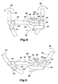
- the first actuating element 68 is thus in a first end position, for example, with the flaps closed, on one side of the second Actuator 70 (Fig. 4).
- the first Actuator 68 has been moved and in a second end position, is moved, for example, with open switching flaps (Fig. 6)
- the first Arret istselement 68 in the direction of movement on the opposite Side of the second locking element 70 is arranged.
- both End positions ensures a very good locking of the flaps 20 because The magnetic forces do not hold the switching flaps 20 in their position, but if necessary, press against correspondingly provided stops.
Landscapes
- Engineering & Computer Science (AREA)
- Chemical & Material Sciences (AREA)
- Combustion & Propulsion (AREA)
- Mechanical Engineering (AREA)
- General Engineering & Computer Science (AREA)
- Health & Medical Sciences (AREA)
- Biomedical Technology (AREA)
- Characterised By The Charging Evacuation (AREA)
- Gear-Shifting Mechanisms (AREA)
- Multiple-Way Valves (AREA)
Abstract
Description
- Fig. 1
- eine schematische Schnittansicht eines Luftansaugkanalsystems mit einer bevorzugten Ausführungsform der Arretierungseinrichtung,
- Fig. 2
- eine schematische Seitenansicht der erfindungsgemäßen Schaltklappenanordnung in vereinfachter Darstellung,
- Fig. 3
- eine schematische Draufsicht der erfindungsgemäßen Schaltklappenanordnung,
- Fig. 4
- eine schematische Seitenansicht einer weiteren Ausführungsform der erfindungsgemäßen Schaltklappenanordnung in geschlossener Stellung,
- Fig. 5
- die in Fig. 4 dargestellte Ausführungsform der Schaltklappenanordnung in einer geschlossenen Endstellung und
- Fig. 6
- die in den Fign. 4 und 5 dargestellte Schaltklappenanordnung in offener Endstellung.
Claims (13)
- Schaltklappenanordnung für Luftansaugkanäle, insbesondere von Brennkraft-V-Motoren zur Längenveränderung der Luftansaugkanäle, mit
mindestens einer Schaltklappe (20),
einer zur Lagerung der Schaltklappe (20) dienenden Schaltwelle (22, 24) und
einer mit der Schaltwelle (22, 24) verbunden Betätigungseinrichtung zum Schalten der Schaltklappe (20),
gekennzeichnet durch
eine Arretierungseinrichtung (54) zum Halten der Schaltklappe (20) in einer Endstellung (20'). - Schaltklappenanordnung nach Anspruch 1, dadurch gekennzeichnet, dass die Arretierungseinrichtung (54) derart ausgebildet ist, dass die Arretierung durch Magnetkräfte erfolgt.
- Schaltklappenanordnung nach Anspruch 1 oder 2, dadurch gekennzeichnet, dass die Schaltklappe (20) und/ oder die Schaltwelle (22, 24) mittelbar oder unmittelbar mit einem ersten Arretierungselement (56,68) verbunden ist, das mit einem zweiten, insbesondere am Saugrohrgehäuse (60) angeordneten Arretierungselement (58,70) zusammenwirkt.
- Schaltklappenanordnung nach einem der Ansprüche 1 - 3, dadurch gekennzeichnet, dass mehrere Schaltklappen (20) mit der Schaltwelle (22, 24) verbunden sind.
- Schaltklappenanordnung nach einem der Ansprüche 1 - 4, gekennzeichnet durch eine zweite Schaltwelle (22), die mindestens eine weitere Schaltklappe (20) trägt, wobei vorzugsweise die zweite Schaltwelle (22) über ein Koppelgestänge (42) mit der ersten Schaltwelle (24) verbunden ist.
- Schaltklappenanordnung nach Anspruch 5, dadurch gekennzeichnet, dass eines der beiden Arretierungselemente (56,58;68,70) mit dem Koppelgestänge (42) verbunden ist, insbesondere an einem in Richtung des Saugrohrgehäuses (60) weisenden Ende einer Koppelstange (42) des Koppelgestänges, angeordnet ist.
- Schaltklappenanordnung nach einem der Ansprüche 3-6, dadurch gekennzeichnet, dass das erste Arretierungselement (68) beim Betätigen der Schaltklappe (20) einen Betätigungsweg zurückgelegt, in dem das zweite Arretierungselement (70) angeordnet ist, wobei das zweite Arretierungselement (70) das erste Arretierungselement (68) zum Erreichen der Endstellung (20') auslenkt.
- Schaltklappenanordnung nach einem der Ansprüche 2-7, dadurch gekennzeichnet, dass die beiden Arretierungselemente (68,70) als Magnete ausgebildet und derart angeordnet sind, dass sie sich gegenseitig abstoßen.
- Schaltklappenanordnung nach einem der Ansprüche 3-8, dadurch gekennzeichnet, dass das erste Arretierungselement (70) an einem sich beim Betätigen der Schaltklappe (20) mitbewegenden Halteelement (62) angeordnet ist.
- Schaltklappenanordnung nach Anspruch 9, dadurch gekennzeichnet, dass das Halteelement (62) mit dem Koppelgestänge (42) verbunden ist.
- Schaltklappenanordnung nach Anspruch 9 oder 10, dadurch gekennzeichnet, dass das Halteelement (62) elastisch auslenkbar ist.
- Schaltklappenanordnung nach einem der Ansprüche 3-11, dadurch gekennzeichnet, dass das erste Arretierungselement (68) in Bewegungsrichtung (72) in einer ersten Endstellung auf einer Seite des zweiten Arretierungselements (70) und in einer zweiten Endstellung auf der gegenüber liegenden Seite des zweiten Arretierungselements (70) angeordnet ist.
- Schaltklappenanordnung nach einem der Ansprüche 1 - 12, dadurch gekennzeichnet, dass zwischen den Arretierungselementen (56, 58) auch in der Offenstellung (20') ein Spalt vorgesehen ist.
Applications Claiming Priority (2)
| Application Number | Priority Date | Filing Date | Title |
|---|---|---|---|
| DE10253287 | 2002-11-15 | ||
| DE10253287A DE10253287A1 (de) | 2002-11-15 | 2002-11-15 | Schaltklappenanordnung |
Publications (3)
| Publication Number | Publication Date |
|---|---|
| EP1428998A2 true EP1428998A2 (de) | 2004-06-16 |
| EP1428998A3 EP1428998A3 (de) | 2005-12-28 |
| EP1428998B1 EP1428998B1 (de) | 2010-07-07 |
Family
ID=32240081
Family Applications (1)
| Application Number | Title | Priority Date | Filing Date |
|---|---|---|---|
| EP03025766A Expired - Lifetime EP1428998B1 (de) | 2002-11-15 | 2003-11-11 | Schaltklappenanordnung |
Country Status (3)
| Country | Link |
|---|---|
| EP (1) | EP1428998B1 (de) |
| DE (2) | DE10253287A1 (de) |
| ES (1) | ES2346860T3 (de) |
Cited By (1)
| Publication number | Priority date | Publication date | Assignee | Title |
|---|---|---|---|---|
| EP2000650A1 (de) * | 2007-06-04 | 2008-12-10 | HONDA MOTOR CO., Ltd. | Ansaugsteuerungssystem für einen Motor |
Family Cites Families (3)
| Publication number | Priority date | Publication date | Assignee | Title |
|---|---|---|---|---|
| KR890000569B1 (ko) * | 1983-09-13 | 1989-03-21 | 미쯔비시 지도샤 고교 가부시끼 가이샤 | 엔진의 흡기통로길이 가변장치 |
| DE4401585C2 (de) * | 1994-01-20 | 1998-10-29 | Mann & Hummel Filter | Drosseleinrichtung |
| DE19614474B4 (de) * | 1996-04-12 | 2005-08-04 | Pierburg Gmbh | Luftansaugkanalsystem für Brennkraftmaschinen |
-
2002
- 2002-11-15 DE DE10253287A patent/DE10253287A1/de not_active Ceased
-
2003
- 2003-11-11 DE DE50312860T patent/DE50312860D1/de not_active Expired - Lifetime
- 2003-11-11 ES ES03025766T patent/ES2346860T3/es not_active Expired - Lifetime
- 2003-11-11 EP EP03025766A patent/EP1428998B1/de not_active Expired - Lifetime
Cited By (2)
| Publication number | Priority date | Publication date | Assignee | Title |
|---|---|---|---|---|
| EP2000650A1 (de) * | 2007-06-04 | 2008-12-10 | HONDA MOTOR CO., Ltd. | Ansaugsteuerungssystem für einen Motor |
| US7997247B2 (en) | 2007-06-04 | 2011-08-16 | Honda Motor Co., Ltd. | Engine intake control system |
Also Published As
| Publication number | Publication date |
|---|---|
| EP1428998A3 (de) | 2005-12-28 |
| ES2346860T3 (es) | 2010-10-21 |
| DE10253287A1 (de) | 2004-06-03 |
| EP1428998B1 (de) | 2010-07-07 |
| DE50312860D1 (de) | 2010-08-19 |
Similar Documents
| Publication | Publication Date | Title |
|---|---|---|
| DE112015003481B4 (de) | Vorrichtung zum Abscheiden von Öltröpfchen und/oder Ölnebel | |
| DE69505763T2 (de) | Ansaugrohr mit Schwenkklappen für eine Brennkraftmaschine | |
| EP1157200B1 (de) | Luftansaugsystem für eine brennkraftmaschine | |
| DE19504382A1 (de) | Ansaugsystem | |
| DE4311369A1 (de) | Ansaugsteuervorrichtung für einen Verbrennungsmotor | |
| EP2504557B1 (de) | Klappenvorrichtung und sauganlage | |
| EP0691461B1 (de) | Ansauganlage für eine Mehrzylinder-Brennkraftmaschine | |
| DE69204031T2 (de) | Abgasrückführungsventilzusammenbau. | |
| WO2001009493A2 (de) | Saugrohranlage | |
| DE102020108125A1 (de) | Verbindungsanordnung und turbolader, der die verbindungsanordnung umfasst | |
| DE19614474A1 (de) | Luftansaugkanalsystem für Brennkraftmaschinen | |
| EP0747587B1 (de) | Einrichtung zur Einstellung der Rohrlänge von Saugrohren und Verfahren zu deren Herstellung | |
| EP2820284B1 (de) | Mischventil einer brennkraftmaschine | |
| DE10204768B4 (de) | Drallverstellbarer Einlasskanal mit zumindest einer in Längsrichtung verlaufenden Trennwand | |
| EP1428998B1 (de) | Schaltklappenanordnung | |
| DE4422055C1 (de) | Einrichtung zur Betätigung einer Anordnung von Leitrohrschiebern | |
| EP0490104A1 (de) | Verfahren zur Steuerung der Luftzufuhr bei einer Brennkraftmaschine | |
| DE10143384C1 (de) | Schaltklappeneinrichtung | |
| DE10319403B4 (de) | Klappenvorrichtung | |
| EP1388652B1 (de) | Ansaugkanalsystem | |
| DE102017109062A1 (de) | Regelvorrichtung für eine Verbrennungskraftmaschine | |
| EP1744047B1 (de) | Saugmodul, insbesondere für eine Brennkraftmaschine | |
| EP1447603B1 (de) | Drosselklappe und Verfahren zu deren Herstellung | |
| DE60125829T2 (de) | Luftklappenlageranordnung | |
| DE102004009502B3 (de) | Klappensystem, insbesondere zur Änderung der Strömungsverhältnisse an Einlassventilen |
Legal Events
| Date | Code | Title | Description |
|---|---|---|---|
| PUAI | Public reference made under article 153(3) epc to a published international application that has entered the european phase |
Free format text: ORIGINAL CODE: 0009012 |
|
| AK | Designated contracting states |
Kind code of ref document: A2 Designated state(s): AT BE BG CH CY CZ DE DK EE ES FI FR GB GR HU IE IT LI LU MC NL PT RO SE SI SK TR |
|
| AX | Request for extension of the european patent |
Extension state: AL LT LV MK |
|
| PUAL | Search report despatched |
Free format text: ORIGINAL CODE: 0009013 |
|
| AK | Designated contracting states |
Kind code of ref document: A3 Designated state(s): AT BE BG CH CY CZ DE DK EE ES FI FR GB GR HU IE IT LI LU MC NL PT RO SE SI SK TR |
|
| AX | Request for extension of the european patent |
Extension state: AL LT LV MK |
|
| 17P | Request for examination filed |
Effective date: 20060503 |
|
| 17Q | First examination report despatched |
Effective date: 20060803 |
|
| AKX | Designation fees paid |
Designated state(s): DE ES FR GB IT |
|
| GRAP | Despatch of communication of intention to grant a patent |
Free format text: ORIGINAL CODE: EPIDOSNIGR1 |
|
| GRAS | Grant fee paid |
Free format text: ORIGINAL CODE: EPIDOSNIGR3 |
|
| GRAA | (expected) grant |
Free format text: ORIGINAL CODE: 0009210 |
|
| AK | Designated contracting states |
Kind code of ref document: B1 Designated state(s): DE ES FR GB IT |
|
| REG | Reference to a national code |
Ref country code: GB Ref legal event code: FG4D Free format text: NOT ENGLISH |
|
| REF | Corresponds to: |
Ref document number: 50312860 Country of ref document: DE Date of ref document: 20100819 Kind code of ref document: P |
|
| REG | Reference to a national code |
Ref country code: ES Ref legal event code: FG2A Ref document number: 2346860 Country of ref document: ES Kind code of ref document: T3 |
|
| PLBE | No opposition filed within time limit |
Free format text: ORIGINAL CODE: 0009261 |
|
| STAA | Information on the status of an ep patent application or granted ep patent |
Free format text: STATUS: NO OPPOSITION FILED WITHIN TIME LIMIT |
|
| 26N | No opposition filed |
Effective date: 20110408 |
|
| REG | Reference to a national code |
Ref country code: DE Ref legal event code: R097 Ref document number: 50312860 Country of ref document: DE Effective date: 20110408 |
|
| GBPC | Gb: european patent ceased through non-payment of renewal fee |
Effective date: 20101111 |
|
| REG | Reference to a national code |
Ref country code: FR Ref legal event code: ST Effective date: 20110801 |
|
| PG25 | Lapsed in a contracting state [announced via postgrant information from national office to epo] |
Ref country code: FR Free format text: LAPSE BECAUSE OF NON-PAYMENT OF DUE FEES Effective date: 20101130 |
|
| REG | Reference to a national code |
Ref country code: DE Ref legal event code: R119 Ref document number: 50312860 Country of ref document: DE Effective date: 20110601 Ref country code: DE Ref legal event code: R119 Ref document number: 50312860 Country of ref document: DE Effective date: 20110531 |
|
| PG25 | Lapsed in a contracting state [announced via postgrant information from national office to epo] |
Ref country code: GB Free format text: LAPSE BECAUSE OF NON-PAYMENT OF DUE FEES Effective date: 20101111 |
|
| PG25 | Lapsed in a contracting state [announced via postgrant information from national office to epo] |
Ref country code: IT Free format text: LAPSE BECAUSE OF NON-PAYMENT OF DUE FEES Effective date: 20101111 |
|
| REG | Reference to a national code |
Ref country code: ES Ref legal event code: FD2A Effective date: 20120110 |
|
| PG25 | Lapsed in a contracting state [announced via postgrant information from national office to epo] |
Ref country code: ES Free format text: LAPSE BECAUSE OF NON-PAYMENT OF DUE FEES Effective date: 20101112 |
|
| PG25 | Lapsed in a contracting state [announced via postgrant information from national office to epo] |
Ref country code: DE Free format text: LAPSE BECAUSE OF NON-PAYMENT OF DUE FEES Effective date: 20110531 |