EP1428730A2 - Système de sécurité pour un véhicule, en particulier pour un véhicule automobile - Google Patents
Système de sécurité pour un véhicule, en particulier pour un véhicule automobile Download PDFInfo
- Publication number
- EP1428730A2 EP1428730A2 EP03024746A EP03024746A EP1428730A2 EP 1428730 A2 EP1428730 A2 EP 1428730A2 EP 03024746 A EP03024746 A EP 03024746A EP 03024746 A EP03024746 A EP 03024746A EP 1428730 A2 EP1428730 A2 EP 1428730A2
- Authority
- EP
- European Patent Office
- Prior art keywords
- airbag
- cover
- lid
- area
- occupant
- Prior art date
- Legal status (The legal status is an assumption and is not a legal conclusion. Google has not performed a legal analysis and makes no representation as to the accuracy of the status listed.)
- Withdrawn
Links
Images


Classifications
-
- B—PERFORMING OPERATIONS; TRANSPORTING
- B60—VEHICLES IN GENERAL
- B60R—VEHICLES, VEHICLE FITTINGS, OR VEHICLE PARTS, NOT OTHERWISE PROVIDED FOR
- B60R21/00—Arrangements or fittings on vehicles for protecting or preventing injuries to occupants or pedestrians in case of accidents or other traffic risks
- B60R21/02—Occupant safety arrangements or fittings, e.g. crash pads
- B60R21/16—Inflatable occupant restraints or confinements designed to inflate upon impact or impending impact, e.g. air bags
- B60R21/20—Arrangements for storing inflatable members in their non-use or deflated condition; Arrangement or mounting of air bag modules or components
- B60R21/215—Arrangements for storing inflatable members in their non-use or deflated condition; Arrangement or mounting of air bag modules or components characterised by the covers for the inflatable member
- B60R21/216—Arrangements for storing inflatable members in their non-use or deflated condition; Arrangement or mounting of air bag modules or components characterised by the covers for the inflatable member comprising tether means for limitation of cover motion during deployment
-
- B—PERFORMING OPERATIONS; TRANSPORTING
- B60—VEHICLES IN GENERAL
- B60R—VEHICLES, VEHICLE FITTINGS, OR VEHICLE PARTS, NOT OTHERWISE PROVIDED FOR
- B60R21/00—Arrangements or fittings on vehicles for protecting or preventing injuries to occupants or pedestrians in case of accidents or other traffic risks
- B60R21/02—Occupant safety arrangements or fittings, e.g. crash pads
- B60R21/16—Inflatable occupant restraints or confinements designed to inflate upon impact or impending impact, e.g. air bags
- B60R21/20—Arrangements for storing inflatable members in their non-use or deflated condition; Arrangement or mounting of air bag modules or components
- B60R21/215—Arrangements for storing inflatable members in their non-use or deflated condition; Arrangement or mounting of air bag modules or components characterised by the covers for the inflatable member
- B60R21/2155—Arrangements for storing inflatable members in their non-use or deflated condition; Arrangement or mounting of air bag modules or components characterised by the covers for the inflatable member with complex motion of the cover; Retraction under the lining during opening
Definitions
- the invention relates to a safety device for a vehicle, in particular for a Motor vehicle, according to the preamble of claim 1.
- a safety device for a is already known from the generic DE 196 33 109 A1 Motor vehicle with an airbag outlet opening formed in a trim part known, which in the non-activated basic state of the safety device by means of a Cover is closed.
- the non-activated basic state is in the range of Airbag outlet opening on the side of the vehicle facing away from the vehicle interior Cladding part arranged an airbag folded, the lid in the activated Condition of the safety device by the inflating airbag to release the Airbag outlet opening can be lifted from this.
- the lid is secured here with a tether, with one end of the Tether is connected to the cover and the other end in the form of a loop is placed around an anchoring element.
- the anchor element for the tether is detachable regardless of components of an airbag module comprising the airbag a fixed holding element of the motor vehicle.
- the lid itself is with Clips attached to a stepped edge of the airbag outlet opening.
- the clips are made of an elastically deformable plastic material or spring steel and are attached at predetermined locations in the edge area.
- each locking anchor which consists of two finger-like, with laterally protruding barbs provided locking elements, which are in the direction of a longitudinal axis of the locking anchor allow to squeeze and when released by the elastic restoring force return to their starting point.
- One of the two locking elements of each locking anchor is a little longer than the other so that when pressed together it is over the shorter one Can put locking element, whereby the cross section of the compressed Latch anchor in the area of the barbs can be further reduced.
- the barbs are closed beveled at the tip of the free end of the locking anchor so that it easily fits into one from several openings, which are placed in the appropriate places in one circumferential flange are provided, the edge of the inside of a Cover carrier sheet protrudes.
- the barbs After clipping in, the barbs reach behind the edge the airbag passage opening and hold the lid in place. The barbs are further also beveled towards a foot of the locking anchor, so that the edge of the Airbag passage opening compresses the locking elements while releasing the cover, when the inflating airbag puts pressure on the inside of the lid carrier sheet exercises.
- the lid, the tether and the anchoring element should be one of the Airbag module be formed separate assembly, the components of which all Airbag module are independent.
- the one from the lid, the tether and the Anchoring element existing assembly should be designed here so that it can be preassembled so that only the lid on the edge of the Airbag outlet opening snapped in and the anchoring element through a hose for the tether is inserted and then needs to be attached to the holding element.
- Through the Separation from the airbag module and by a corresponding, from the back of the Attachment of the airbag module accessible here can be used for inspection or maintenance can be removed without opening the cover or closing the tether to solve.
- the lid When the lid is pressed open by the inflating airbag, it becomes immediately lifted from the airbag outlet opening and z. B. in connection with a Dashed forward toward the windshield, the Tether an uncontrolled flying around of the lid and thus a risk of Vehicle occupants prevented.
- EP 0 940 300 A1 describes a cover arrangement for an airbag outlet opening in a motor vehicle known in which the lid when it is lifted off the Airbag outlet opening by means of one or more hinge straps during its Opening movement is kept on a defined trajectory.
- the hinge strap is attached to the lid so that the folded over the airbag arranged behind the panel spanned.
- an airbag arrangement for a vehicle is known from DE 44 41 365 A1, in which a cover closing an airbag outlet opening in its closed position so-called magnetic connector is held. This should on the one hand in the Closed position formed a sufficiently stable connection and on the other hand a largely unbraked immediate opening pressure generated by the airbag The airbag outlet opening can be released by lifting the cover.
- EP 0 846 600 A1 describes a connection of an airbag outlet opening closing lid known, in which the lid is secured with a tether that Similar to EP 0 940 300 A1 after an immediate lifting of the lid from the Airbag outlet opening at the beginning of the activation process of the safety device Cover forward toward the windshield with one essentially Translated lid kinematics transferred.
- an instrument panel for a motor vehicle is known from DE 198 23 048 A1
- a cover which is an independent press part.
- a profiled sheet is attached to the inside surface of the cover.
- Such a profiled sheet for stiffening the cover is also known from DE 198 15 267 A1 known.
- DE 198 47 386 A1 also describes a safety device for a motor vehicle known, in which in the space between the airbag module and the cover dimensionally stable packing unit is arranged, which fills the space.
- the Packing device has a corresponding to the desired pressure distribution the expanding airbag and the lid designed curved surface on which the expanding airbag attacks. The more volume of the space through the Packing unit is covered, the earlier the expansion of the airbag unit to the Transfer coverage.
- the filling device being designed in such a way that in connection with a cover arrangement in a passenger side area of an instrument panel the cover is first lifted from the airbag outlet opening area with its end near the occupant, for the earliest possible release of the airbag outlet opening and an inflation of the Airbags in the direction of the vehicle occupants.
- the object of the invention is to provide a safety device for a vehicle, in particular for to create a motor vehicle with which an even better targeted expansion of an airbag is possible when the safety device is activated.
- the lid is at the opening edge area of the airbag outlet opening tied that this first with the one by the inflating airbag Vehicle end seat position facing away from the far end of the cover from the Airbag outlet opening can be raised and with one of the vehicle occupant seating position facing lid end area near the occupant, the lid end remote from the occupant opposite, continue in a cover holding area of the airbag outlet opening by means of a holding connection is held such that between the trim part and the lifted lid area a side and opposite the lid holding area rear airbag outlet gap is formed, through which an airbag subarea does not directly in the direction of the assigned vehicle occupant seat position in the Vehicle interior is deployable into it.
- the airbag outlet opening detachable to completely lift the cover off the airbag outlet opening and thus for the complete release of the airbag outlet opening for inflating the airbag toward the associated vehicle occupant seating position.
- the safety device With such a construction of the safety device, it is advantageously achieved that the Danger of impairment for occupants that occurs at the moment of airbag deployment are outside of a normal sitting position, d. H. a so-called out-of-position situation is given, as is the case for example in the instrument panel area Children or non-belted vehicle occupants can be significantly reduced, since the safety device according to the invention the airbag does not deploy first in the direction of the vehicle occupant, but rather Start of the unfolding process only by the between the trim part and the lifted lid area trained airbag outlet gap in the direction Vehicle interior can leak.
- the Deployment kinematics of the airbag can be particularly the beginning of the inflation process occurring load peaks can be significantly reduced, because then the energy input is stretched in time.
- the airbag exit gap is particularly preferred here formed that the airbag initially on the side lid edge areas, d. H. unfolded tangentially to the occupant.
- the rear airbag outlet gap area is for this preferably blocked by appropriate measures.
- the lid at the beginning of the lifting process is located in the lid holding area
- the lid pivot axis can be swung open. This will make it simple and good Lid kinematics reached at the beginning of the inflation process.
- the blanket is particularly preferred! a substantially rectangular shape, so that a first side of the rectangle away from the occupant and the two sides of the rectangle at least in some areas by means of a first connecting device with a predefinable one first holding force is held at the associated outlet opening edge area.
- the second holding force is greater than the first holding force, so that in the event of a force caused by the inflation of the airbag on the Cover underside, which is greater than the first holding force and smaller than the second holding force, the lid with the first side of the rectangle and at least partially with the side Rectangular sides of the airbag outlet opening edge area to form the Airbag exit gap lifts off. With a subsequent increase in force the airbag lifts further and the second holding force is exceeded then also in the lid holding area from the airbag outlet opening edge area.
- the second is provided for this Connection device through a continuous tongue and groove connection in the lid holding area to form at the associated airbag outlet opening edge region.
- the first connecting device on the first side of the rectangle by individual, spaced latching connections may be formed, while again the first Connection device on the sides of the rectangle each by a continuous Tongue and groove connection and / or by individual, spaced apart Snap connections is formed.
- Such tongue and groove connections and from each other spaced snap connections are relative with a high degree of functional reliability easy to produce inexpensively.
- the individual, spaced-apart locking connections by individual corresponding Detent noses assigned to locking recesses can be formed.
- the near-end lid end area can also in Lid holding area by means of at least one additional hinge strap z. B. on one be arranged under the trim part holding frame so that this Hinged band then sounds out of a positive fit if e.g. B. certain Opening angle can be reached.
- the underside of the lid can also be designed such that the Airbag at the beginning of the inflation process essentially exerts a force on the exercising away from the end of the lid.
- this flat covering reinforcement plate attached which with a cover area remote from the occupant-associated sheet metal area further in the direction protrudes towards the airbag as an approximately in relation to the Extension direction between the near-occupant and distant end of the lid in the middle area as a transition area adjoining and close to the occupant Sheet metal area assigned to the lid area.
- This ensures that the inflating Airbag at the beginning of the inflation process essentially first on the far-away Sheet metal area strikes and preferably an opening moment around one in the lid holding area horizontal cover pivot axis causes.
- this can Reinforcing sheet as simple and at least in the sheet metal area away from the occupant inexpensive hollow profile be double-edged. Such a structure is relative easy to manufacture.
- the shape and stiffness of the lid and the reinforcement plate can further increase, at least in the vicinity of the occupants, preferably in the whole Sheet metal stiffening beads can be provided.
- the reinforcement plate can be used in various ways
- the underside of the lid is a preferred option and / or rivets for fixing the reinforcement plate on the underside of the lid.
- the transition region between the near-occupant and the can be particularly advantageous sheet metal area remote from the occupant may be convex to form a directional ramp for the inflating airbag.
- the lid with at least one tether is secured.
- This tether is on the one hand on the lid a connection point on the cover side and on the other hand in the area of Airbag outlet opening on the side of the vehicle facing away from the vehicle interior Cover part connected in another connection point.
- the invention provides that the at least one tether on the one hand in the area of the Airbag outlet opening edge is connected below the end of the lid remote from the occupant and on the other hand is connected to the lid end area near the occupant.
- the at least one tether in the non-activated basic state of the Safety device spans the folded airbag and from above covers at least some areas.
- the at least one tether is preferred dimensioned so that the inflating airbag at the beginning of the inflation process at least one tether in at least some areas in an investment connection on the The underside of the lid converts to the targeted application by inflating the airbag pressing force acting on the lid.
- Such a tether can in principle also by z. B. a sheet metal strip or the like be formed.
- the at least one tether is formed by a single sail that extends approximately the entire lid width extends between the lateral lid edge areas.
- Such a sail is relatively simple and inexpensive to manufacture with a high level of functional reliability.
- the sail has in the area of the cover-side connection point on a protective flap, which when the Pressing force of the airbag caused the cover to be lifted from the cover holding area between the inflating airbag and the edge area of the near-by occupant Lid end attaches to prevent damage to the airbag.
- the protective flap is in the inactive state of the safety device a free end in the area of the airbag outlet opening area below the near the occupant end of the lid and below the lid-side connection point fixed, preferably glued, for a defined transfer of the protective flap as Edge protection in the protective position covering the end of the lid near the occupant the pressing force of the airbag caused the cover to be lifted from the cover holding area.
- the end portion of the cover remote from the occupant is in this case preferred concrete embodiment of the invention so long while maintaining the Lid-holding connection between the lid end area near the occupant and the lid-holding area lifted from the assigned airbag outlet opening edge area until the at least a second tether is tightened or the pressing force is greater than that Holding force of the lid-holding connection.
- connection points can each advantageously be by a Fastening rod, which preferably has a tube cross section, be formed on the the sail in each case by means of loops, preferably by means of spaced apart Loops is fixed.
- a first end of the sail is advantageous for training at least one loop sewn for fixing at the second connection point, while to form at least one loop for attachment to the first Connection point on the cover side, a second one opposite the first sail end
- the end of the sail is sewn in such a way that a protective flap protruding therefrom is formed.
- Such a sail is simple in terms of cutting and overall with relatively little effort producible, d. that is, only a single strip or rag of sail material is required, which is attached to the loops by the sewing described the spaced connection points and the protective flap.
- the sail is preferably formed by a fabric material in which the warp and Weft threads to avoid combing, preferably at an angle of 30 to 60 °, most preferably woven together at an angle of 45 °.
- a first Tether on the one hand in a first connection point on the lid area remote from the occupant and on the other hand in a second connection point, which is related to the Airbag outlet opening level approximately in a straight extension below the first Connection point is in the lid area remote from the occupant, connected.
- a second The tether is on the one hand at or adjacent to the second connection point of the first tether and on the other hand in a third connection point close to the occupant Cover area tied so that the first and second tether in the non-activated Basic state are unstressed in the area behind the trim part.
- the airbag lifts the end of the lid away from the occupant for so long until the first tether is tightened. Then by inflating of the airbag increases the push-on force of the lid-holding connection of the lid in the lid holding area released to release the entire airbag outlet opening, the The cover is lifted until the second tether is tightened. Subsequently the lid can then be particularly advantageous by means of the tightened lateral tether straps can be folded back towards the vehicle occupant. With a Such a structure results in a particularly advantageous cover kinematics overall advantageous to the overall functional reliability of the safety device effect.
- At least one first tether is advantageous formed that this the rear airbag outlet gap area, the lid holding area opposite, locks, so that the airbag at the beginning of the inflation process only through the two lateral airbag exit gap areas approximately tangential to the lateral lid edge areas with the advantages already explained in detail in the Unfolded vehicle interior.
- z. B. the first tether by Formed sail that extends approximately over the entire width of the lid between the side Cover edge areas extends.
- both the first and that second tether can be designed as such a sail, so that with such a structure the second tether essentially block the rear airbag exit gap area would.
- connection points that are not on the cover by at least one Fastening rod are formed, which on a below the trim part arranged holding frame is attached.
- a holding frame is essentially around the airbag outlet opening is arranged around and also serves as a double function Attachment option for other components, especially to determine the Airbag module, which has the airbag and a gas generator.
- this holding frame also a protective flap possibly protruding from the sail by z.
- the cover is a Airbag flap is in the passenger area of an instrument panel.
- the lid end area close to the occupant in the windshield the rear instrument panel area facing away and the lid end area remote from the occupant in the
- the front instrument panel wall area near the windscreen is arranged horizontally.
- the Lateral lid areas are seen in the longitudinal direction of the instrument panel opposite, the lid preferably having a rectangular shape. All above considerations made are thus in each case with such a use in To see cross section through the instrument panel longitudinal direction, d. H. that the Cut in the longitudinal direction of the vehicle.
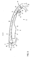
- a safety device 1 is shown schematically in a plan view, wherein only a cover 2 of an airbag outlet opening 3 is shown. For reasons of clarity the components forming the airbag outlet opening 3 and adjacent to the cover 2 in FIG. 1 omitted.
- the lid 2 of the Safety device 1 these components are each partly drawn in.
- the lid 2 has a rectangular shape, with a flat on the underside of the lid covering reinforcement plate 4 is attached.
- the cover 2 is assigned to the airbag outlet opening 3 exemplarily formed in the passenger-side area of an instrument panel 5, so that the Cover 2 forms an airbag flap in the instrument panel 5.
- the lid 2 has a Cover end 6 near the occupant, which faces a passenger seat position (not shown) is, and a remote end of the lid end 7, which faces away from the passenger seat position. Because of the close arrangement of the two cutting lines A-A and E-E on both lateral rectangle sides 8 and 9 is the airbag outlet opening edge area in the Instrument panel 5 below the cover 2 shown partially in dashed lines.
- the lid 2 is so arranged on the instrument panel 5 that the cutting lines A-A and E-E approximately in Direction of travel.
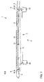
- FIG. 3 schematically shows a sectional view along the section line B-B of FIG. 1 shown.
- the reinforcing plate 4, which is arranged on the underside of the cover 2, is formed as a double-walled hollow profile, the two sheet metal layers 10 and 11 of the Reinforcement plate 4 in the area close to the occupant, the end 6 near the occupant is assigned, are less spaced than in the area remote from the occupant, which Lid end 7 remote from the occupant is assigned.
- the transition area between the near the occupant and the distant sheet metal area is curved to form a directional ramp 12 for an airbag 13 not shown here. Am close to the occupant lid end 6 is on the underside in Fig.4ff.
- the sail 14 extends (Fig. 4ff) approximately over the entire length of the lid between the two lateral sides of the rectangle 8 and 9 of the lid 2.
- a close to the occupant end 6 associated attachment point 16 of the sail 14, which by means of the rivet connection 15 is connected to the underside of the lid is by a Fastening rod 17 formed with a tube cross section, on which the sail 14 with preferably several loops 18 is held.
- connection point 16 of the sail 14 at the end 6 near the occupant stands here, as a variant, a protective flap 21 as edge protection for the airbag 13, the one with a body-fixed holding frame 22 which around the airbag outlet opening 3rd is running all round, is glued. On the exact function of the protective flap 21 will received later.
- the sail 14 spans the entire airbag area and extends to a second connection point 23, which is below the distant Cover end 7 is arranged on the holding frame 22. At this end of the sail 14 likewise at least one loop 24 is formed, through which a fastening rod 25 is inserted, which can be fixed in its end regions on the holding frame 22.
- Airbag module 29 with the airbag 13 folded therein in the non-activated basic state is here shown in two different installation positions, one of the two installation positions is shown in dashed lines to distinguish.
- Instrument panel longitudinal direction as vehicle transverse direction continuous tongue and groove connection 19 formed in a lid holding area 46.
- Snap connections 20 are formed, one of which is shown by way of example in FIG. 3. This Locking connections are formed by locking lugs 20 'which engage in the locking groove 20 ".
- FIG. 6 schematically shows a sectional view along the section line F-F from FIG. 1 shown. It is cut through the lid 2 in its longitudinal extent, the Longitudinal extension of the cover 2 of the vehicle transverse direction in the exemplary Arrangement of the safety device 1 in an instrument panel area on the passenger side equivalent.
- On the two sides of the rectangle 8 and 9 is also as on a continuous tongue and groove connection 19 'is formed near the occupant's lid end 6, so that from the side of the rectangle 8 as the first U-leg over the occupant Cover end 6 as a U-base towards the second lateral rectangular side 9 as a second U-leg a U-shaped continuous tongue and groove connection 19, 19 'is formed.
- a reinforcement plate 4 in both sheet metal layers 10 and 11 A variety of stiffening beads 26 can be formed.
- Each in the edge area of the Airbag outlet opening 3 below the cover 2 here is also the holding frame 22 detect.
- FIG. 5 schematically shows a sectional view along the section line D-D from FIG. 1 shown.
- the reinforcement plate 4 designed as a double-walled hollow profile is in each case at the end of the cover 6 and 7 near the occupant and away from the occupant with its upper sheet metal layer 10 attached to the underside of the lid 2 by means of a rivet connection 15.
- the Reinforcing plate 4 extends between the two lateral sides of the rectangle 8 and 9. In section D-D shown in FIG. 5, this is at least in regions Stiffening beads 26 shown.
- the protective tab 21 attached to the holding frame 22 is here only shown in dashed lines as an option.
- FIG. 7 schematically shows a sectional view along the section line G-G from FIG. 5 shown. Again, the sides of the rectangle 8 and 9 in the Continuous tongue and groove connection 19 'in and out of the image plane with the Airbag outlet opening edge area of the instrument panel 5 can be seen.
- the top sheet layer 10 of the reinforcement plate 4 is connected to the underside of the cover 2 by means of the Rivet connections 15 connected, one in the lower sheet metal layer 11 Rivet connection 15 assigned a through opening for attaching the rivet connection is.
- the holding frame 22 is closed at the edge of the airbag outlet opening 3 detect.
- the rivet connections 15 shown in FIG. 7 correspond to the connection of the Reinforcement plate 4 at the end of the cover 7 remote from the occupant, the ones shown in FIG. 8 Rivet connections 15 the fastening points of the reinforcement plate 4 near the occupant Cover end 6 correspond.
- the section shown schematically in FIG. 8 runs along the section line H-H of Fig. 1st
- FIG. 9 schematically shows a top view of the sail 14.
- the area associated with the near-end cover end 6 has three Loops 18 through which the fastening rod 17 is inserted (not here ) Shown.
- the second connection point 23 of the sail 14 is analogous to the opposite side through the three loops 24 through which the fastening rod 25 (not shown) is formed.
- the loops 18 and 24 are each through Sewing by means of seams 27 and 28, which run in the longitudinal direction of the sail 14, is formed.
- FIG. 10 which schematically shows a sectional view along the section line I-I of FIG FIG. 9 shows, it can be seen, the sail 14 becomes so in the area of the loops 18 to be formed sewn over that the protective flap 21 is formed.
- 11 to 14 each schematically shows a sectional view along the section line C-C of FIG. 1 in the non-activated basic state of the safety device 1 or in Various inflation positions of the airbag 13 of the safety device 1 shown for Explanation of the functioning of the safety device 1:
- the Airbag 13 is in a folded state in an airbag module 29.
- the sail 14 is between the first connection point 16 and the second Connection point 23 arranged and spans the airbag 13 or the airbag module 29.
- the lid 2 runs with its top surface flush with the top of the Instrument panel 5.
- a stiffening bead 26 of the reinforcement plate 4 is dashed drawn between the two sheet layers 10 and 11.
- a hinge strap 30 which covers the cover 2 with the holding frame 22 connects. The hinge strap 30 is only shown in broken lines in FIG. 11.
- the Cover pivot axis 32 is formed in the area of the tongue and groove connection 19 and runs approximately parallel to that assigned to the end 6 of the cover close to the occupant Rectangular side of the cover 2.
- an arrow 34 is drawn in in FIG. 12.
- an airbag exit gap 33 is formed, which in the direction of the Rectangular side of the cover 2 assigned to the remote end of the cover 7 by means of the sail 14 is blocked for an airbag outlet. This allows the airbag 13 at the beginning of Activation of the safety device 1 not directly in the direction of that of the instrument panel 5 assigned passenger seat position, but only tangentially through the side Airbag exit gap areas of the airbag exit gap 33.
- This first inflation position is also shown schematically in FIG. 15 in a plan view or 16 is shown in a front view.
- Fig. 15 that is below the lid 2 above Area of the airbag module 29 stretched sail 14 shown in dashed lines. Due to the Blocking of the airbag exit gap 33 in the direction of the end 7 of the cover remote from the occupant assigned rectangle side of the lid 2 by means of the sail 14, the airbag 13 can The beginning of its deployment only tangentially through the lateral airbag outlet gap areas of the Unfold airbag exit gap 33, which can be clearly seen in FIG. 15. With this targeted The deployment kinematics of the airbag 13 can be influenced in particular at the beginning of the inflating load peaks can be significantly reduced because here then the energy input is stretched in time. In Fig.
- a schematic Front view from the perspective of a passenger is that on the two side Rectangular sides 8 and 9, mainly emerging airbag 13 can also be seen.
- the in Cover-holding area 46 formed tongue and groove connection 19 is in this Inflation state due to their opposite latching connection 20 with the individual Latches 20 'greater holding force have not yet been released, so that in the area of the tongue and groove connection the lid pivot axis 32 is formed.
- FIG. 17 This is the second inflation position in FIG. 17 as a top view and in FIG. 18 as a front view shown schematically.
- the tongue and groove connection 19 in the lid holding area 46 is now loosened so that the cover 2 for a complete lift-off from the airbag outlet opening 3 is released.
- the airbag 13 can thus now also move in the direction of the passenger unfold. At this point, the peak loads at the beginning of the Inflation of the airbag occur, dismantled and the airbag can decrease Inflate aggressiveness towards the passenger to protect him.
- the hinge strap 30 shown in FIG. 11 is shown in FIGS Figs. 12, 13 and 14 are omitted.
- Such a possibly additional hinge band 30 is preferably designed such that at the beginning of the deployment of the airbag 13 and one Swiveling the lid 2 about the lid pivot axis 32, the hinge band 30 this pivoting is defined up to a certain opening angle and then when a greater deployment force of the airbag 13 is reached, the connection between the Hinge strap 30 and the lid 2 or the holding frame 22 is released for complete lifting of the cover 2 from the airbag outlet opening 3.
- This third inflation position is in a plan view in FIG. 19 and in a in FIG. 20 Front view shown schematically.
- the complete lifting of the lid 2 is with a Arrow 37 shown in Fig. 19, the sail 14 with the function of a tether prevents it from flying around in an uncontrolled manner.
- FIG. 21 to 23 schematically show an alternative embodiment of a Safety device 1 'shown with sectional views. Components with the same design and function as in the safety device 1 are given the same reference numerals Mistake.
- FIG. 21 schematically shows a non-activated basic state of the safety device 1 ', in which a first tether 38 in a first connection point 40 at the cover end 7 remote from the occupant and on the other hand in a second connection point 41, which is approximately in a straight extension below the level of the airbag outlet opening of the first connection point 40 lies in the cover area 7 remote from the occupant, is connected.
- the second tether 39 is connected on the one hand to the second attachment point 41 of the first tether 38 and on the other hand in a third attachment point 42 to the lid end 6 near the occupant, so that the first and second tether 38 and 39 are arranged untensioned in the area behind the instrument panel 5 in the non-activated basic state ,
- the tether 38 is designed as a continuous sail and thus extends approximately over the entire length of the lid from one side of the rectangular side 8 and to the other side of the rectangular side 9, ie perpendicular to the plane of the drawing.
- the tether 39 is arranged on both sides of the cover 2 and is assigned to one of the two lateral sides 8 and 9 of the rectangle.
- the deploying airbag 13 lifts the end 7 of the cover remote from the occupant until the first tether 38 is tightened.
- FIG. 22 The holding force on the cover holding area is designed so that the tongue and groove connection 19 is not initially released.
- the lid 2 thus pivots about the lid pivot axis formed in the lid holding area to form the airbag exit gap 33. Due to the sail formed by the tether 38, deployment of the airbag 13 in the direction of the rectangle side of the lid 2 associated with the end 7 of the lid remote from the occupant is blocked, so that the airbag 13 at the beginning of its deployment largely unfolds only tangentially through the lateral airbag gap regions of the airbag gap 33.
- the inflation of the airbag 13 is shown by an arrow 43 and the lifting of the cover 2 at the end 7 remote from the occupant is shown by an arrow 44 in FIG. 22.
- FIG. 23 the cover 2 is completely lifted from the airbag outlet opening 3, which is due to the further deployment of the airbag 13 is conditioned.
- the arrow 43 in FIG. 23 is again the Inflation of the airbag marked and the associated displacement of the lid 2 away from the occupant is shown with an arrow 45 in FIG. 23.
Landscapes
- Engineering & Computer Science (AREA)
- Mechanical Engineering (AREA)
- Air Bags (AREA)
Applications Claiming Priority (2)
| Application Number | Priority Date | Filing Date | Title |
|---|---|---|---|
| DE10257758 | 2002-12-10 | ||
| DE2002157758 DE10257758A1 (de) | 2002-12-10 | 2002-12-10 | Sicherheitseinrichtung für ein Fahrzeug, insbesondere für ein Kraftfahrzeug |
Publications (2)
| Publication Number | Publication Date |
|---|---|
| EP1428730A2 true EP1428730A2 (fr) | 2004-06-16 |
| EP1428730A3 EP1428730A3 (fr) | 2004-11-17 |
Family
ID=32319034
Family Applications (1)
| Application Number | Title | Priority Date | Filing Date |
|---|---|---|---|
| EP03024746A Withdrawn EP1428730A3 (fr) | 2002-12-10 | 2003-10-29 | Système de sécurité pour un véhicule, en particulier pour un véhicule automobile |
Country Status (2)
| Country | Link |
|---|---|
| EP (1) | EP1428730A3 (fr) |
| DE (1) | DE10257758A1 (fr) |
Cited By (2)
| Publication number | Priority date | Publication date | Assignee | Title |
|---|---|---|---|---|
| WO2006057632A1 (fr) * | 2004-11-23 | 2006-06-01 | Johnson Controls Technology Company | Surface de reaction separee pour un panneau de garnissage de vehicule |
| JP2012176662A (ja) * | 2011-02-25 | 2012-09-13 | Toyoda Gosei Co Ltd | エアバッグドアの位置決め構造 |
Families Citing this family (4)
| Publication number | Priority date | Publication date | Assignee | Title |
|---|---|---|---|---|
| DE102007029769B3 (de) * | 2007-06-22 | 2008-11-20 | Faurecia Innenraum Systeme Gmbh | Airbagklappe mit Rotationsbegrenzer |
| DE102007032712B4 (de) | 2007-07-13 | 2016-11-24 | GM Global Technology Operations LLC (n. d. Ges. d. Staates Delaware) | Kraftfahrzeuginneneinrichtung mit einem Innenverkleidungsteil mit einer Austrittsöffnung für einen Gassack |
| DE102013109962A1 (de) | 2013-09-11 | 2015-04-09 | Dr. Ing. H.C. F. Porsche Aktiengesellschaft | Sicherheitsvorrichtung für ein Fahrzeug, insbesondere für ein Kraftfahrzeug |
| US11247632B2 (en) | 2019-10-07 | 2022-02-15 | Ford Global Technologies, Llc | Airbag assembly with releasable panel |
Citations (7)
| Publication number | Priority date | Publication date | Assignee | Title |
|---|---|---|---|---|
| DE4441365A1 (de) | 1994-11-21 | 1995-10-12 | Daimler Benz Ag | Airbaganordnung für einen Fahrgastraum eines Kraftfahrzeuges |
| DE19633109A1 (de) | 1995-08-25 | 1997-02-27 | Volkswagen Ag | Airbag-Rückhaltesystem |
| EP0846600A1 (fr) | 1996-12-06 | 1998-06-10 | Ford Global Technologies, Inc. | Améliorations relatives aux systèmes d'attache de couvercle pour coussin de sécurité |
| DE19823048A1 (de) | 1997-05-22 | 1998-11-26 | Skoda Auto As | Armaturenbrett aus Kunststoff für Kraftfahrzeuge |
| EP0940300A1 (fr) | 1998-03-03 | 1999-09-08 | Bayerische Motoren Werke Aktiengesellschaft | Couvercle pour un système de retenue d'un véhicule |
| DE19847386A1 (de) | 1998-10-14 | 1999-09-23 | Daimler Chrysler Ag | Aufprallschutzvorrichtung |
| DE19815267A1 (de) | 1998-04-04 | 1999-10-07 | Volkswagen Ag | Airbagaufnahme in einer Instrumententafel eines Kraftfahrzeugs |
Family Cites Families (4)
| Publication number | Priority date | Publication date | Assignee | Title |
|---|---|---|---|---|
| DE19546001C2 (de) * | 1995-12-09 | 1999-07-01 | Autoliv Dev | Scharniergehalterte Abdeckklappe für eine Airbag-Anordnung |
| US5651562A (en) * | 1996-02-28 | 1997-07-29 | Trw Inc. | Release mechanism |
| FR2768675B1 (fr) * | 1997-09-19 | 1999-12-03 | Reydel Sa | Element d'equipement interieur pour vehicule, notamment vehicule automobile |
| DE19958865B4 (de) * | 1999-12-07 | 2009-11-12 | Peguform Gmbh | Luftsackabdeckvorrichtung sowie Einrichtung und Verfahren zur Herstellung einer Luftsackabdeckvorrichtung |
-
2002
- 2002-12-10 DE DE2002157758 patent/DE10257758A1/de not_active Withdrawn
-
2003
- 2003-10-29 EP EP03024746A patent/EP1428730A3/fr not_active Withdrawn
Patent Citations (7)
| Publication number | Priority date | Publication date | Assignee | Title |
|---|---|---|---|---|
| DE4441365A1 (de) | 1994-11-21 | 1995-10-12 | Daimler Benz Ag | Airbaganordnung für einen Fahrgastraum eines Kraftfahrzeuges |
| DE19633109A1 (de) | 1995-08-25 | 1997-02-27 | Volkswagen Ag | Airbag-Rückhaltesystem |
| EP0846600A1 (fr) | 1996-12-06 | 1998-06-10 | Ford Global Technologies, Inc. | Améliorations relatives aux systèmes d'attache de couvercle pour coussin de sécurité |
| DE19823048A1 (de) | 1997-05-22 | 1998-11-26 | Skoda Auto As | Armaturenbrett aus Kunststoff für Kraftfahrzeuge |
| EP0940300A1 (fr) | 1998-03-03 | 1999-09-08 | Bayerische Motoren Werke Aktiengesellschaft | Couvercle pour un système de retenue d'un véhicule |
| DE19815267A1 (de) | 1998-04-04 | 1999-10-07 | Volkswagen Ag | Airbagaufnahme in einer Instrumententafel eines Kraftfahrzeugs |
| DE19847386A1 (de) | 1998-10-14 | 1999-09-23 | Daimler Chrysler Ag | Aufprallschutzvorrichtung |
Cited By (2)
| Publication number | Priority date | Publication date | Assignee | Title |
|---|---|---|---|---|
| WO2006057632A1 (fr) * | 2004-11-23 | 2006-06-01 | Johnson Controls Technology Company | Surface de reaction separee pour un panneau de garnissage de vehicule |
| JP2012176662A (ja) * | 2011-02-25 | 2012-09-13 | Toyoda Gosei Co Ltd | エアバッグドアの位置決め構造 |
Also Published As
| Publication number | Publication date |
|---|---|
| EP1428730A3 (fr) | 2004-11-17 |
| DE10257758A1 (de) | 2004-07-22 |
Similar Documents
| Publication | Publication Date | Title |
|---|---|---|
| EP0999101B1 (fr) | Dispositif de protection à sac gonflable contre des chocs latéraux | |
| EP1681209B1 (fr) | Dispositif de sac gonflable latéral | |
| DE4027996C2 (de) | Gassacksystem | |
| EP2015969B1 (fr) | Systeme d'airbag pour dispositif de retenue des passagers d'un vehicule | |
| EP1919738B1 (fr) | Dispositif d'airbag pour un véhicule automobile | |
| DE102007005922B4 (de) | Richtungsgeber für die Entfaltung eines Airbags | |
| WO2020260364A1 (fr) | Module de coussin gonflable pour conducteur et dispositif de direction comprenant un module de coussin gonflable pour conducteur de ce type | |
| DE10063473A1 (de) | Dachholm-Verkleidung für aufblasbares Rückhaltesystem | |
| DE69834722T2 (de) | Sitzintegrierter luftsack-entfaltungsdeckel | |
| DE102006060688C5 (de) | Innenverkleidungsteil | |
| EP1428730A2 (fr) | Système de sécurité pour un véhicule, en particulier pour un véhicule automobile | |
| EP1438218A1 (fr) | Systeme d'airbag situe dans un vehicule, notamment une automobile | |
| EP2195203A1 (fr) | Élément porteur de tableau de bord avec système de volet pour airbag | |
| DE19824735B4 (de) | Airbagmodul für ein Fahrzeug | |
| DE102020116832A1 (de) | Fahrzeugairbaganordnung und zugeordnetes Ausbildungsverfahren | |
| DE10039803B4 (de) | Fahrzeugdach, insbesondere für ein Kraftfahrzeug | |
| EP1034988B1 (fr) | Fixation pour la planche de bord d'une voiture automobile pourvue d'un coussin gonflable | |
| DE10039802B4 (de) | Sicherheitseinrichtung für die Insassen eines Fahrzeugs, insbesondere eines Kraftfahrzeugs | |
| EP0861759B1 (fr) | Module de sac gonflable côté passager | |
| DE10307964A1 (de) | Anordnung einer Airbagabdeckung | |
| DE10111597B4 (de) | Insassenschutzvorrichtung für ein Fahrzeug, insbesondere für ein Kraftfahrzeug | |
| EP1716022A1 (fr) | Recouvrement de sac gonflable pour vehicule a moteur | |
| DE102006031529B4 (de) | Kopfairbag mit Träger und Dekor | |
| EP2841310B1 (fr) | Protection anti-déchirure sur une couture de sortie de coussin gonflable latéral d'un revêtement de siège de véhicule et revêtement de siège de véhicule doté d'une protection anti-déchirure | |
| DE4308909A1 (de) | Abdeckungsanbringungsstruktur, insbesondere Modulabdeckungsanbringungsstruktur einer Luftsackeinrichtung für einen Fahrgast |
Legal Events
| Date | Code | Title | Description |
|---|---|---|---|
| PUAI | Public reference made under article 153(3) epc to a published international application that has entered the european phase |
Free format text: ORIGINAL CODE: 0009012 |
|
| AK | Designated contracting states |
Kind code of ref document: A2 Designated state(s): AT BE BG CH CY CZ DE DK EE ES FI FR GB GR HU IE IT LI LU MC NL PT RO SE SI SK TR |
|
| AX | Request for extension of the european patent |
Extension state: AL LT LV MK |
|
| PUAL | Search report despatched |
Free format text: ORIGINAL CODE: 0009013 |
|
| AK | Designated contracting states |
Kind code of ref document: A3 Designated state(s): AT BE BG CH CY CZ DE DK EE ES FI FR GB GR HU IE IT LI LU MC NL PT RO SE SI SK TR |
|
| AX | Request for extension of the european patent |
Extension state: AL LT LV MK |
|
| 17P | Request for examination filed |
Effective date: 20050517 |
|
| AKX | Designation fees paid |
Designated state(s): AT BE BG CH CY CZ DE DK EE ES FI FR GB GR HU IE IT LI LU MC NL PT RO SE SI SK TR |
|
| GRAP | Despatch of communication of intention to grant a patent |
Free format text: ORIGINAL CODE: EPIDOSNIGR1 |
|
| STAA | Information on the status of an ep patent application or granted ep patent |
Free format text: STATUS: THE APPLICATION IS DEEMED TO BE WITHDRAWN |
|
| 18D | Application deemed to be withdrawn |
Effective date: 20060221 |