EP1428265B1 - Photovoltaik-isolierverglasung - Google Patents
Photovoltaik-isolierverglasung Download PDFInfo
- Publication number
- EP1428265B1 EP1428265B1 EP02777171A EP02777171A EP1428265B1 EP 1428265 B1 EP1428265 B1 EP 1428265B1 EP 02777171 A EP02777171 A EP 02777171A EP 02777171 A EP02777171 A EP 02777171A EP 1428265 B1 EP1428265 B1 EP 1428265B1
- Authority
- EP
- European Patent Office
- Prior art keywords
- photo
- voltaic
- insulating glazing
- accordance
- spacer
- Prior art date
- Legal status (The legal status is an assumption and is not a legal conclusion. Google has not performed a legal analysis and makes no representation as to the accuracy of the status listed.)
- Expired - Lifetime
Links
- 239000011521 glass Substances 0.000 claims abstract description 39
- 125000006850 spacer group Chemical group 0.000 claims abstract description 39
- 238000007789 sealing Methods 0.000 claims description 6
- 210000002445 nipple Anatomy 0.000 claims description 4
- 230000015572 biosynthetic process Effects 0.000 claims 1
- 239000000565 sealant Substances 0.000 description 9
- 238000004519 manufacturing process Methods 0.000 description 5
- 229910052782 aluminium Inorganic materials 0.000 description 3
- XAGFODPZIPBFFR-UHFFFAOYSA-N aluminium Chemical compound [Al] XAGFODPZIPBFFR-UHFFFAOYSA-N 0.000 description 3
- 239000004020 conductor Substances 0.000 description 2
- 238000009434 installation Methods 0.000 description 2
- 238000000034 method Methods 0.000 description 2
- XLYOFNOQVPJJNP-UHFFFAOYSA-N water Chemical compound O XLYOFNOQVPJJNP-UHFFFAOYSA-N 0.000 description 2
- 238000004026 adhesive bonding Methods 0.000 description 1
- 239000013013 elastic material Substances 0.000 description 1
- 238000010292 electrical insulation Methods 0.000 description 1
- 230000007613 environmental effect Effects 0.000 description 1
- 230000006870 function Effects 0.000 description 1
- 238000009413 insulation Methods 0.000 description 1
- 238000005304 joining Methods 0.000 description 1
- 230000013011 mating Effects 0.000 description 1
- 229910052751 metal Inorganic materials 0.000 description 1
- 239000002184 metal Substances 0.000 description 1
- 239000007769 metal material Substances 0.000 description 1
- 239000012811 non-conductive material Substances 0.000 description 1
- 230000009993 protective function Effects 0.000 description 1
- 238000005476 soldering Methods 0.000 description 1
- 239000006228 supernatant Substances 0.000 description 1
Images

Classifications
-
- H—ELECTRICITY
- H01—ELECTRIC ELEMENTS
- H01L—SEMICONDUCTOR DEVICES NOT COVERED BY CLASS H10
- H01L31/00—Semiconductor devices sensitive to infrared radiation, light, electromagnetic radiation of shorter wavelength or corpuscular radiation and specially adapted either for the conversion of the energy of such radiation into electrical energy or for the control of electrical energy by such radiation; Processes or apparatus specially adapted for the manufacture or treatment thereof or of parts thereof; Details thereof
- H01L31/02—Details
- H01L31/02002—Arrangements for conducting electric current to or from the device in operations
- H01L31/02005—Arrangements for conducting electric current to or from the device in operations for device characterised by at least one potential jump barrier or surface barrier
- H01L31/02008—Arrangements for conducting electric current to or from the device in operations for device characterised by at least one potential jump barrier or surface barrier for solar cells or solar cell modules
-
- H—ELECTRICITY
- H01—ELECTRIC ELEMENTS
- H01L—SEMICONDUCTOR DEVICES NOT COVERED BY CLASS H10
- H01L31/00—Semiconductor devices sensitive to infrared radiation, light, electromagnetic radiation of shorter wavelength or corpuscular radiation and specially adapted either for the conversion of the energy of such radiation into electrical energy or for the control of electrical energy by such radiation; Processes or apparatus specially adapted for the manufacture or treatment thereof or of parts thereof; Details thereof
- H01L31/04—Semiconductor devices sensitive to infrared radiation, light, electromagnetic radiation of shorter wavelength or corpuscular radiation and specially adapted either for the conversion of the energy of such radiation into electrical energy or for the control of electrical energy by such radiation; Processes or apparatus specially adapted for the manufacture or treatment thereof or of parts thereof; Details thereof adapted as photovoltaic [PV] conversion devices
- H01L31/042—PV modules or arrays of single PV cells
- H01L31/048—Encapsulation of modules
- H01L31/0488—Double glass encapsulation, e.g. photovoltaic cells arranged between front and rear glass sheets
-
- C—CHEMISTRY; METALLURGY
- C09—DYES; PAINTS; POLISHES; NATURAL RESINS; ADHESIVES; COMPOSITIONS NOT OTHERWISE PROVIDED FOR; APPLICATIONS OF MATERIALS NOT OTHERWISE PROVIDED FOR
- C09K—MATERIALS FOR MISCELLANEOUS APPLICATIONS, NOT PROVIDED FOR ELSEWHERE
- C09K2323/00—Functional layers of liquid crystal optical display excluding electroactive liquid crystal layer characterised by chemical composition
- C09K2323/05—Bonding or intermediate layer characterised by chemical composition, e.g. sealant or spacer
-
- Y—GENERAL TAGGING OF NEW TECHNOLOGICAL DEVELOPMENTS; GENERAL TAGGING OF CROSS-SECTIONAL TECHNOLOGIES SPANNING OVER SEVERAL SECTIONS OF THE IPC; TECHNICAL SUBJECTS COVERED BY FORMER USPC CROSS-REFERENCE ART COLLECTIONS [XRACs] AND DIGESTS
- Y02—TECHNOLOGIES OR APPLICATIONS FOR MITIGATION OR ADAPTATION AGAINST CLIMATE CHANGE
- Y02E—REDUCTION OF GREENHOUSE GAS [GHG] EMISSIONS, RELATED TO ENERGY GENERATION, TRANSMISSION OR DISTRIBUTION
- Y02E10/00—Energy generation through renewable energy sources
- Y02E10/50—Photovoltaic [PV] energy
-
- Y—GENERAL TAGGING OF NEW TECHNOLOGICAL DEVELOPMENTS; GENERAL TAGGING OF CROSS-SECTIONAL TECHNOLOGIES SPANNING OVER SEVERAL SECTIONS OF THE IPC; TECHNICAL SUBJECTS COVERED BY FORMER USPC CROSS-REFERENCE ART COLLECTIONS [XRACs] AND DIGESTS
- Y10—TECHNICAL SUBJECTS COVERED BY FORMER USPC
- Y10T—TECHNICAL SUBJECTS COVERED BY FORMER US CLASSIFICATION
- Y10T428/00—Stock material or miscellaneous articles
- Y10T428/22—Nonparticulate element embedded or inlaid in substrate and visible
-
- Y—GENERAL TAGGING OF NEW TECHNOLOGICAL DEVELOPMENTS; GENERAL TAGGING OF CROSS-SECTIONAL TECHNOLOGIES SPANNING OVER SEVERAL SECTIONS OF THE IPC; TECHNICAL SUBJECTS COVERED BY FORMER USPC CROSS-REFERENCE ART COLLECTIONS [XRACs] AND DIGESTS
- Y10—TECHNICAL SUBJECTS COVERED BY FORMER USPC
- Y10T—TECHNICAL SUBJECTS COVERED BY FORMER US CLASSIFICATION
- Y10T428/00—Stock material or miscellaneous articles
- Y10T428/24—Structurally defined web or sheet [e.g., overall dimension, etc.]
- Y10T428/24777—Edge feature
Definitions
- the invention relates to a photovoltaic insulating glazing comprising a multilayer glazing with a photovoltaic module, wherein contact strips for contacting the photovoltaic module are led out of the photovoltaic module and wherein a spacer for spacing the glass layers to form the gap is provided, the z. B. is formed from a rail, wherein in the spacer at least one opening is provided, by means of which the contact strip and an electrical connection element via a bolt which is inserted into the opening, and wherein the contact strip with the provided outside of the glass layers electrical Connecting element cooperates.
- photovoltaic modules in insulating glazes via a glass layer z. B. from a double glass, in which the solar cells embedded or on which they are applied.
- This module usually provides the one layer of insulating glazing.
- the other is formed by a glass pane. Between glass pane and photovoltaic module there is a space between the panes, which can be filled with gas to form an insulating glazing.
- Such an arrangement is z. B. from the EP 199 233 A1 known.
- the invention also includes other types of photovoltaic modules.
- the invention solves this problem by a photovoltaic insulating glazing with the features of claim 1.
- the lead out of the contact strip from the photovoltaic module takes place laterally from the module layers.
- the spacer may then be located either between the inner module cover and the glass sheet or between the outer module cover and the glass sheet.
- the inner module cover must be shortened in relation to the outer one.
- the attachment of the contact ribbon is done as described below.
- the contact strip does not occur in the space between the panes, but occurs completely outside the insulating glazing to light.
- the definition is then also like that of the external connection element "from the outside", either by fixing it via a cable lug or pinching the same between the bore wall and bolt.
- the bore in the spacer and / or the connector does not pass into the space between the panes, but only the outer side has an opening. The tightness of the space between the panes will not be affected.
- the contact strip is then finally also enclosed by the insulation in the finished disc.
- the spacer may comprise individual elements and connecting elements, wherein the individual elements are connected via the connecting elements, wherein the openings can then be holes in the connecting elements.
- the fasteners can be commercially available linear or corner connectors for insulating glass spacers with a hole, so that no additional manufacturing effort arises.
- one or more holes may be provided in the spacer itself.
- the bore also serves as Gasbehellö réelle for the insulating glass.
- the bore has a thread and the bolt is screwed into it.
- the bolt can also be pressed into the bore.
- the contact strip extends through the bore and is clamped by the thread of the bolt.
- an electrical connection element can serve for example a connection cable with a cable lug, wherein the contact strip is in direct communication with the cable lug.
- the bolt may in this case for example have a nut, or a bolt head, through which the cable lug between the wall of the connecting element and / or the spacer and the head of the bolt is clamped and thus held non-positively. This will set the external connector.
- the contact strip and thus the module connection itself is then strain-relieved and the opening in the spacer and / or connecting element is closed at the same time, so that the gas introduced into the insulating glass pane is held in the space between the panes.
- the bolts may consist of electrically conductive or non-conductive material and different embodiments, such as. B. blind rivet, expansion sleeve or the like.
- an elastic sealing nipple is provided to seal the glass pane gap with respect to the outside of the glass layers. In this way, the gas and vapor tightness can be guaranteed even better.
- the connectors can be made of plastic. It can be provided that the spacers, which are formed from, for example, aluminum hollow profiles, are pushed onto the connectors and clamped there. In particular, an interference fit can be provided in this case.
- a cable lug may be provided, to which a connection cable is attached.
- the spacers are made of electrically conductive material, it may be provided that non-conductive washers are used in order to avoid electrical contact between the bolt and the spacer profiles and thus short circuits.
- openings are provided in the spacer profile itself, an electrical insulation is always necessary, provided that they are made of conductive material.
- plastic hollow sections can be omitted.
- a conventional glazing block can be provided with preferably 0.5 to 8 mm thickness, which can also serve as a glazing block in addition to its protective function for the cable outlet.
- connection cables are not crushed during installation between substructure and glass beyond.
- Such a block may have groove-shaped recesses along the glass edge for receiving the cable, which offer the additional advantage of increased sealant coverage in the region of the electrical connection.
- the block on its side facing the glass supernatants in the form of, for example, barbs that press when gluing the pad in the sealant and lead to curing of the sealant to an additional positive connection between the block and sealant.
- the holes can be stepped holes.
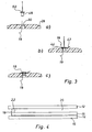
- FIG. 1 shows an insulating glazing consisting of two outer glass panes 12 and 14.
- the disc 14 forms the outer cover of a photovoltaic module 16.
- the inner cover forms the disc 15. Between the discs 15, 16, the solar cells are arranged.
- a contact strip 18 is arranged in the photovoltaic module 16 as an electrical connection.
- the contact strip 18 is guided through a hole in the inner cover 15 into the space between the panes 20.
- a commercially available spacer 22 is provided, through which the electrical connection from the space between the panes 20 can be led to the outside and there with an electrical connection element 26, usually a external cable, can be brought into contact.
- the space between the panes 20 is filled with gas, as is the case with insulating glazings. The electrical connection must therefore be gas and vapor-tight.
- the spacers 22 are made of aluminum hollow profile elements, which are made by plastic fasteners 28, as in FIG. 2 are shown, connected by an aluminum hollow profile is pushed onto both sides of a connecting element 28 and held there by frictional engagement.
- the connecting elements 28 have a Bore 30 on.
- connection element 28 is provided with a stepped hole 30, this being in representation a) of FIG. 2 can be seen.
- Presentation a) of FIG. 2 shows the corresponding connecting element 28 in section and the bottom thereof. In the direction of arrow 32, the hollow profiles of the spacer 22 are pushed onto the connecting element 28.
- FIG. b) it is now shown how a special sealing nipple 34 made of elastic material with integrated threaded nut 36 is inserted into the stepped bore 30.
- a threaded bolt 38 which is shown in representation c) clamped by screwing with the integrated threaded nut 36 on the one hand, the sealing nipple 34 with the shaft of the threaded bolt 38 and on the other hand with the connecting element 28 gas-tight.
- a commercial cable lug 40 is fastened to the threaded bolt 38, which serves for making electrical contact with a contact strip 18 of the photovoltaic module 16.
- the thus equipped connecting element 28 is installed in the insulating glass spacer 22, wherein a connecting element 28 per contact strip 18 is used.
- the contact points are first recessed or provided with a suitable cover.
- the external connecting cable is now electrical Connection element 42, which is also provided with a cable lug 44, fixed by means of a threaded nut 46 on the threaded bolt 38.
- electrical Connection element 42 which is also provided with a cable lug 44, fixed by means of a threaded nut 46 on the threaded bolt 38.
- connection After mounting the external connection cable, the connection is sealed with sealant and thus also electrically insulated.
- non-electrically conductive washers are additionally used under the cable lugs 44, 40 in order to avoid that when mating the spacer profiles 22, which may consist of a metallic material, with the connecting elements 28 an electrical contact between bolts 38 and spacer profiles 22 occurs, which could cause a short circuit.
- FIG. 3 shows now three illustration a) to c) of a further variant of the electrical contacting, wherein like parts are to be provided here with the same reference numerals.
- a bore 30 is again provided in the connecting element 28, through which the contact strip 18 is threaded.
- the bolt used here is a blind rivet 48, under the head 50 of which a cable lug 44 is pushed.
- the cable lug 44 is in turn connected to the electrical connection element 42.
- the blind rivet 48 is from the outside inserted into the hole 30 and there, as shown in the illustrations b) and c) attached.
- the cable lug 44 which surrounds the blind rivet 48 is fixed under the head 50 of the blind rivet 48 and at the same time the contact band 18 is clamped between the wall of the bore 30 and the rivet 48.
- the contact strip 18 is directly contacted with the electrical connection 42 via the cable lug 44 and, as can be seen well in illustration c), the bore 30 is closed. On the electrical conductivity of the bolt or blind rivet it does not matter then.
- this solution has the advantage that the assembly of the rivet 48 can take place only after the assembly of the insulating glass pane.
- the holes 30 can then simultaneously serve as Gasbehellö réelle the insulating glass.
- FIG. 1 be provided to provide two holes, wherein the contact strip 18 is led out through a first hole 30 from the disc space 20, wherein the hole 30 completely penetrates the spacer 22 and after passing the contact strip 18 is closed with a stopper, and next to a second hole provided is, which is formed from the outside of the spacer ago 22 in particular as a blind hole.
- this second hole can then, as analogous to FIG. 4 described, the determination of the ribbon 18 and the contacting done.
- FIG. 4 shows a variant of the invention, in which the contact strip 18 is brought from the outside to the electrical connection.
- the spacer 22 is disposed between the inner module cover 15 and the glass sheet 12.
- the cable ribbon exits between the inner 15 and the outer module cover 14, and is determined analogously to the above-described definition "from the outside" in the spacer 22.
- the protruding ribbon 18 is thereby pushed back into the hole or folded folded on the back of the spacer 22.
Landscapes
- Engineering & Computer Science (AREA)
- Physics & Mathematics (AREA)
- Condensed Matter Physics & Semiconductors (AREA)
- Electromagnetism (AREA)
- General Physics & Mathematics (AREA)
- Computer Hardware Design (AREA)
- Microelectronics & Electronic Packaging (AREA)
- Power Engineering (AREA)
- Life Sciences & Earth Sciences (AREA)
- Sustainable Development (AREA)
- Sustainable Energy (AREA)
- Securing Of Glass Panes Or The Like (AREA)
- Joining Of Glass To Other Materials (AREA)
- Photovoltaic Devices (AREA)
- Liquid Crystal (AREA)
- Insulating Bodies (AREA)
Applications Claiming Priority (3)
| Application Number | Priority Date | Filing Date | Title |
|---|---|---|---|
| DE10146498A DE10146498C2 (de) | 2001-09-21 | 2001-09-21 | Photovoltaik-Isolierverglasung |
| DE10146498 | 2001-09-21 | ||
| PCT/EP2002/010620 WO2003028114A2 (de) | 2001-09-21 | 2002-09-20 | Photovoltaik-isolieverglasung |
Publications (2)
| Publication Number | Publication Date |
|---|---|
| EP1428265A2 EP1428265A2 (de) | 2004-06-16 |
| EP1428265B1 true EP1428265B1 (de) | 2008-08-06 |
Family
ID=7699751
Family Applications (1)
| Application Number | Title | Priority Date | Filing Date |
|---|---|---|---|
| EP02777171A Expired - Lifetime EP1428265B1 (de) | 2001-09-21 | 2002-09-20 | Photovoltaik-isolierverglasung |
Country Status (7)
| Country | Link |
|---|---|
| US (1) | US7834265B2 (ja) |
| EP (1) | EP1428265B1 (ja) |
| JP (1) | JP2005504441A (ja) |
| AT (1) | ATE403939T1 (ja) |
| DE (2) | DE10146498C2 (ja) |
| ES (1) | ES2311630T3 (ja) |
| WO (1) | WO2003028114A2 (ja) |
Families Citing this family (16)
| Publication number | Priority date | Publication date | Assignee | Title |
|---|---|---|---|---|
| DE10361184B3 (de) * | 2003-12-24 | 2005-02-03 | Glaswerke Arnold Gmbh & Co. Kg | Photovoltaik-Isolierglasscheibe |
| DE102006007472B4 (de) * | 2006-02-17 | 2018-03-22 | Fraunhofer-Gesellschaft zur Förderung der angewandten Forschung e.V. | Photovoltaisches Konzentratormodul mit Multifunktionsrahmen |
| BRPI0908401A2 (pt) * | 2008-02-28 | 2019-05-28 | New Millennium Solar Equipment Corp | unidade de vidro isolante com dispositivo de minijunção integrado |
| DE102008019703C5 (de) * | 2008-04-18 | 2024-02-15 | Harrexco Ag | Verfahren und Vorrichtung zum Durchführen einer elektrischen Isolationsprüfung an Photovoltaikmodulen |
| DE102008030652A1 (de) | 2008-06-27 | 2009-12-31 | Dracowo Forschungs- Und Entwicklungs Gmbh | Stoffe und Verfahren zur Herstellung Photovoltaik aktiver Fassadenelemente |
| BE1020124A3 (fr) * | 2011-07-20 | 2013-05-07 | Agc Glass Europe | Panneau de vitrage isolant comprenant au moins un espace interne comprenant un lame d'un gaz isolant. |
| WO2013038409A2 (en) * | 2011-09-12 | 2013-03-21 | Pythagoras Solar Inc. | Electrical joint |
| JP5746957B2 (ja) * | 2011-12-02 | 2015-07-08 | 株式会社エクソル | 太陽電池モジュールの架台支持構造 |
| FI20116266A (fi) * | 2011-12-13 | 2013-06-14 | Kone Corp | Eristetty hissin tason ovi |
| US20130319598A1 (en) | 2012-05-30 | 2013-12-05 | Cardinal Ig Company | Asymmetrical insulating glass unit and spacer system |
| US20140021903A1 (en) * | 2012-07-18 | 2014-01-23 | Veka Inc. | Windows and doors having integrated solar powered charging devices |
| EP2706306B1 (de) | 2012-09-07 | 2016-05-18 | ODB-Tec GmbH & Co.KG | Isolierglasanordnung und Verfahren zu seiner Herstellung |
| AU2013354388B2 (en) * | 2012-12-03 | 2016-04-14 | Kingspan Holdings (Irl) Limited | A composite insulating panel |
| US10763778B2 (en) * | 2015-12-09 | 2020-09-01 | Brian Patrick Janowski | Solar window construction and methods |
| US11489483B2 (en) * | 2015-12-09 | 2022-11-01 | Brian Patrick Janowski | Solar window construction and methods |
| US10211776B2 (en) * | 2015-12-09 | 2019-02-19 | Brian Patrick Janowski | Solar window construction and methods |
Family Cites Families (38)
| Publication number | Priority date | Publication date | Assignee | Title |
|---|---|---|---|---|
| JPS5328751B2 (ja) * | 1974-11-27 | 1978-08-16 | ||
| US4083097A (en) * | 1976-11-30 | 1978-04-11 | The United States Of America As Represented By The Administrator Of The National Aeronautics And Space Administration | Method of making encapsulated solar cell modules |
| CH616203A5 (en) * | 1977-03-11 | 1980-03-14 | Giesbrecht Alfred Wwe Soehne | Insulating glass pane |
| GB1554507A (en) * | 1977-04-28 | 1979-10-24 | Tideland Signal Corp | Enclosure for solar cells |
| FR2423621A1 (fr) * | 1978-04-17 | 1979-11-16 | Saint Gobain | Entree de fils electriques a l'interieur d'un vitrage multiple |
| BE876681A (fr) * | 1978-06-14 | 1979-11-30 | Bfg Glassgroup | Procede de fabrication d'un panneau comprenant au moins une cellule photovoltaique et panneau comprenant au moins une telle cellule |
| US4167644A (en) * | 1978-09-29 | 1979-09-11 | Exxon Research & Engineering Co. | Solar cell module |
| DE3014246C2 (de) * | 1980-04-14 | 1983-05-19 | Bfg Glassgroup, Paris | Isolierglaseinheit |
| US4401839A (en) * | 1981-12-15 | 1983-08-30 | Atlantic Richfield Company | Solar panel with hardened foil back layer |
| US4582953A (en) * | 1983-06-24 | 1986-04-15 | Kyocera Corporation | Solar cell module |
| DE3330305A1 (de) * | 1983-08-23 | 1985-03-14 | Rainer 6072 Dreieich Bauer | Fenster |
| EP0199233B1 (de) * | 1985-04-17 | 1990-01-31 | Siemens Aktiengesellschaft | Bauelement für den Hochbau und seine Verwendung |
| US4607132A (en) * | 1985-08-13 | 1986-08-19 | Jarnagin William S | Integrated PV-thermal panel and process for production |
| EP0250691B1 (fr) * | 1986-06-23 | 1990-09-05 | Emaillerie Alsacienne Commerciale Et Industrielle, S.A. | Panneau de façade en verre |
| US4832755A (en) | 1987-08-11 | 1989-05-23 | The Boeing Company | Glass encapsulation of solar cell arrays to minimize voltage/plasma interaction effects in a space environment |
| DE3903521C2 (de) * | 1989-02-07 | 1993-11-25 | Kunert Heinz | Transparentes Element zur Verwendung als Fenster-, Wand, Dach- oder Brüstungselement |
| US5167724A (en) * | 1991-05-16 | 1992-12-01 | The United States Of America As Represented By The United States Department Of Energy | Planar photovoltaic solar concentrator module |
| DE4128766C2 (de) | 1991-08-29 | 1995-07-20 | Flachglas Ag | Solarmodul sowie Verfahren zu dessen Herstellung |
| DE4227860A1 (de) * | 1991-09-19 | 1993-04-01 | Aug Guttendoerfer Gmbh & Co | Photovoltaische platte, insbesondere zum einsatz als fassadenplatte |
| DE4300480A1 (de) * | 1993-01-11 | 1994-07-14 | Kunert Heinz | Sicherheitsglaselement mit Wärmedämmeigenschaften |
| DE4301128A1 (de) * | 1993-01-18 | 1994-07-21 | Schueco Int Kg | Fassadenelement |
| EP0615045A1 (de) * | 1993-03-12 | 1994-09-14 | Peter Lisec | Anordnung zum elektrisch leitenden Verbinden |
| US5460660A (en) * | 1993-07-21 | 1995-10-24 | Photon Energy, Inc. | Apparatus for encapsulating a photovoltaic module |
| US5589006A (en) * | 1993-11-30 | 1996-12-31 | Canon Kabushiki Kaisha | Solar battery module and passive solar system using same |
| DE19508222C1 (de) * | 1995-03-08 | 1996-06-05 | Siemens Ag | Optoelektronischer Wandler und Herstellverfahren |
| ATA90695A (de) * | 1995-05-30 | 1998-08-15 | Lisec Peter | Isolierglasscheibe mit fotovoltaischem element |
| FR2752012B3 (fr) * | 1996-07-31 | 1998-08-21 | Saint Gobain Vitrage | Procede pour realiser le vide entre deux feuilles de verre et vitrage isolant |
| FR2762039B1 (fr) * | 1997-04-11 | 1999-06-04 | Saint Gobain Vitrage | Element vitre a haut pouvoir isolant |
| US6262358B1 (en) * | 1999-02-18 | 2001-07-17 | Sharp Kabushiki Kaisha | Solar cell module and solar cell panel using the same |
| US6311455B1 (en) * | 1999-10-01 | 2001-11-06 | Odl, Incorporated | Insulated glass spacer with integral muntin |
| DE19958879A1 (de) * | 1999-12-07 | 2001-07-05 | Saint Gobain | Bauelement mit einer Leitungsdurchführung |
| FR2815374B1 (fr) * | 2000-10-18 | 2003-06-06 | Saint Gobain | Vitrage feuillete et ses moyens d'etancheification peripherique |
| US6589613B1 (en) * | 2000-11-20 | 2003-07-08 | Heinz Kunert | Insulating glass element for glazing a building |
| JP4076742B2 (ja) * | 2001-07-13 | 2008-04-16 | シャープ株式会社 | 太陽電池モジュール |
| US6646196B2 (en) * | 2001-11-26 | 2003-11-11 | Apogee Enterprises, Inc. | Window structure with photovoltaic panel |
| US6793971B2 (en) * | 2001-12-03 | 2004-09-21 | Cardinal Ig Company | Methods and devices for manufacturing insulating glass units |
| GB2385086B (en) * | 2002-02-12 | 2005-10-12 | Torgut Tony Munir | A seal for an evacuated window |
| DE20302045U1 (de) * | 2003-02-10 | 2003-07-10 | Wulfmeier Solar Gmbh | Photovoltaik-Module mit PVB (Polyvinyl-Butyral)-Folie |
-
2001
- 2001-09-21 DE DE10146498A patent/DE10146498C2/de not_active Expired - Fee Related
-
2002
- 2002-09-20 JP JP2003531537A patent/JP2005504441A/ja active Pending
- 2002-09-20 WO PCT/EP2002/010620 patent/WO2003028114A2/de active IP Right Grant
- 2002-09-20 AT AT02777171T patent/ATE403939T1/de active
- 2002-09-20 US US10/490,144 patent/US7834265B2/en not_active Expired - Fee Related
- 2002-09-20 DE DE50212608T patent/DE50212608D1/de not_active Expired - Lifetime
- 2002-09-20 ES ES02777171T patent/ES2311630T3/es not_active Expired - Lifetime
- 2002-09-20 EP EP02777171A patent/EP1428265B1/de not_active Expired - Lifetime
Also Published As
| Publication number | Publication date |
|---|---|
| JP2005504441A (ja) | 2005-02-10 |
| ES2311630T3 (es) | 2009-02-16 |
| DE50212608D1 (de) | 2008-09-18 |
| WO2003028114A3 (de) | 2003-09-25 |
| US7834265B2 (en) | 2010-11-16 |
| WO2003028114A2 (de) | 2003-04-03 |
| DE10146498A1 (de) | 2003-04-24 |
| ATE403939T1 (de) | 2008-08-15 |
| DE10146498C2 (de) | 2003-11-20 |
| EP1428265A2 (de) | 2004-06-16 |
| US20050034754A1 (en) | 2005-02-17 |
Similar Documents
| Publication | Publication Date | Title |
|---|---|---|
| EP1428265B1 (de) | Photovoltaik-isolierverglasung | |
| DE10361184B3 (de) | Photovoltaik-Isolierglasscheibe | |
| EP0798787B1 (de) | Photovoltaisches Solarmodul in Plattenform | |
| EP3743584A1 (de) | Abstandhalter für isolierverglasungen mit integriertem flachbandkabel | |
| DE102009012539A1 (de) | Verbindungsvorrichtung zum Anschluss an ein Solarmodul und Solarmodul mit einer solchen Verbindungsvorrichtung | |
| DE10249992C1 (de) | Durchsichtige Scheibe mit einer undurchsichtigen Kontaktfläche für eine Lötverbindung | |
| DE102012010277A1 (de) | Elektrisches Verbindungssystem | |
| WO2014009491A1 (de) | Kantenverbinder für photovoltaische solarmodule | |
| EP3339633A1 (de) | Verfahren zur herstellung einer potentialausgleichsverbindung an einem windenergieanlagenrotorblatt und windenergieanlagenrotorblatt mit einer potentialausgleichsverbindung | |
| EP3361036A1 (de) | Modul zur energieübertragung | |
| EP2605280A1 (de) | Metallisches Bauelement oder Flacherzeugnis mit photovoltaisch wirksamer Beschichtung, Verfahren zu dessen Herstellung und aus solchen, miteinander elektrisch verschalteten Bauelementen gebildete Verkleidung | |
| EP3743582A1 (de) | Isolierverglasung, fenster und verfahren zur herstellung | |
| EP4101030B1 (de) | Flachleiteranschlusselement | |
| DE60018359T2 (de) | Bauelement mit einer Kabeldurchführung sowie Herstellungsverfahren für dasselbe | |
| EP0475417A2 (de) | Anordnung von Führungselementen für elektrische Leitungen im Fassadenbereich von Gebäuden | |
| EP0609651B1 (de) | Fassadenelement | |
| WO2019141532A1 (de) | Isolierverglasung und fenster | |
| EP4183970A2 (de) | Stromabführungssystem für eine beschattungseinrichtung und beschattungseinrichtung hierfür | |
| DE102012111440A1 (de) | Fenster, Tür oder Fassadenelement mit einer Isolierleiste mit integriertem Leuchtmittel | |
| EP2811239B1 (de) | Distanzhalter | |
| DE60014480T2 (de) | Elektronikgehäuse | |
| DE19748868C1 (de) | Isolierglasscheibe mit elektrischer Leiterschleife | |
| DE102016120279A1 (de) | Abdichtungselement und Verfahren zum Abdichten eines Fensterbankabschlusses | |
| DE10319607B3 (de) | Korrosionsschutzschaltung für eine Leiterstruktur auf einer Antennenscheibe, Verfahren zum Betreiben einer aktiven Antennenscheibe und Antennenscheibe für Fahrzeuge | |
| DE202006020185U1 (de) | Scheibenelement mit einer elektrischen Leitstruktur |
Legal Events
| Date | Code | Title | Description |
|---|---|---|---|
| PUAI | Public reference made under article 153(3) epc to a published international application that has entered the european phase |
Free format text: ORIGINAL CODE: 0009012 |
|
| 17P | Request for examination filed |
Effective date: 20040303 |
|
| AK | Designated contracting states |
Kind code of ref document: A2 Designated state(s): AT BE BG CH CY CZ DE DK EE ES FI FR GB GR IE IT LI LU MC NL PT SE SK TR |
|
| RIN1 | Information on inventor provided before grant (corrected) |
Inventor name: SCHMIDT, CHRISTOPH |
|
| 17Q | First examination report despatched |
Effective date: 20060810 |
|
| GRAP | Despatch of communication of intention to grant a patent |
Free format text: ORIGINAL CODE: EPIDOSNIGR1 |
|
| GRAS | Grant fee paid |
Free format text: ORIGINAL CODE: EPIDOSNIGR3 |
|
| GRAA | (expected) grant |
Free format text: ORIGINAL CODE: 0009210 |
|
| AK | Designated contracting states |
Kind code of ref document: B1 Designated state(s): AT BE BG CH CY CZ DE DK EE ES FI FR GB GR IE IT LI LU MC NL PT SE SK TR |
|
| REG | Reference to a national code |
Ref country code: GB Ref legal event code: FG4D Free format text: NOT ENGLISH |
|
| REG | Reference to a national code |
Ref country code: CH Ref legal event code: EP |
|
| REG | Reference to a national code |
Ref country code: IE Ref legal event code: FG4D Free format text: LANGUAGE OF EP DOCUMENT: GERMAN |
|
| REF | Corresponds to: |
Ref document number: 50212608 Country of ref document: DE Date of ref document: 20080918 Kind code of ref document: P |
|
| REG | Reference to a national code |
Ref country code: CH Ref legal event code: NV Representative=s name: MICHELI & CIE SA |
|
| REG | Reference to a national code |
Ref country code: GR Ref legal event code: EP Ref document number: 20080402987 Country of ref document: GR |
|
| PG25 | Lapsed in a contracting state [announced via postgrant information from national office to epo] |
Ref country code: NL Free format text: LAPSE BECAUSE OF FAILURE TO SUBMIT A TRANSLATION OF THE DESCRIPTION OR TO PAY THE FEE WITHIN THE PRESCRIBED TIME-LIMIT Effective date: 20080806 |
|
| REG | Reference to a national code |
Ref country code: ES Ref legal event code: FG2A Ref document number: 2311630 Country of ref document: ES Kind code of ref document: T3 |
|
| PG25 | Lapsed in a contracting state [announced via postgrant information from national office to epo] |
Ref country code: FI Free format text: LAPSE BECAUSE OF FAILURE TO SUBMIT A TRANSLATION OF THE DESCRIPTION OR TO PAY THE FEE WITHIN THE PRESCRIBED TIME-LIMIT Effective date: 20080806 |
|
| REG | Reference to a national code |
Ref country code: IE Ref legal event code: FD4D |
|
| PG25 | Lapsed in a contracting state [announced via postgrant information from national office to epo] |
Ref country code: MC Free format text: LAPSE BECAUSE OF NON-PAYMENT OF DUE FEES Effective date: 20080930 Ref country code: IE Free format text: LAPSE BECAUSE OF FAILURE TO SUBMIT A TRANSLATION OF THE DESCRIPTION OR TO PAY THE FEE WITHIN THE PRESCRIBED TIME-LIMIT Effective date: 20080806 Ref country code: DK Free format text: LAPSE BECAUSE OF FAILURE TO SUBMIT A TRANSLATION OF THE DESCRIPTION OR TO PAY THE FEE WITHIN THE PRESCRIBED TIME-LIMIT Effective date: 20080806 Ref country code: BG Free format text: LAPSE BECAUSE OF FAILURE TO SUBMIT A TRANSLATION OF THE DESCRIPTION OR TO PAY THE FEE WITHIN THE PRESCRIBED TIME-LIMIT Effective date: 20081106 |
|
| PG25 | Lapsed in a contracting state [announced via postgrant information from national office to epo] |
Ref country code: CZ Free format text: LAPSE BECAUSE OF FAILURE TO SUBMIT A TRANSLATION OF THE DESCRIPTION OR TO PAY THE FEE WITHIN THE PRESCRIBED TIME-LIMIT Effective date: 20080806 Ref country code: SK Free format text: LAPSE BECAUSE OF FAILURE TO SUBMIT A TRANSLATION OF THE DESCRIPTION OR TO PAY THE FEE WITHIN THE PRESCRIBED TIME-LIMIT Effective date: 20080806 Ref country code: PT Free format text: LAPSE BECAUSE OF FAILURE TO SUBMIT A TRANSLATION OF THE DESCRIPTION OR TO PAY THE FEE WITHIN THE PRESCRIBED TIME-LIMIT Effective date: 20090106 |
|
| PLBE | No opposition filed within time limit |
Free format text: ORIGINAL CODE: 0009261 |
|
| STAA | Information on the status of an ep patent application or granted ep patent |
Free format text: STATUS: NO OPPOSITION FILED WITHIN TIME LIMIT |
|
| 26N | No opposition filed |
Effective date: 20090507 |
|
| PG25 | Lapsed in a contracting state [announced via postgrant information from national office to epo] |
Ref country code: EE Free format text: LAPSE BECAUSE OF FAILURE TO SUBMIT A TRANSLATION OF THE DESCRIPTION OR TO PAY THE FEE WITHIN THE PRESCRIBED TIME-LIMIT Effective date: 20080806 |
|
| PG25 | Lapsed in a contracting state [announced via postgrant information from national office to epo] |
Ref country code: SE Free format text: LAPSE BECAUSE OF FAILURE TO SUBMIT A TRANSLATION OF THE DESCRIPTION OR TO PAY THE FEE WITHIN THE PRESCRIBED TIME-LIMIT Effective date: 20081106 |
|
| PG25 | Lapsed in a contracting state [announced via postgrant information from national office to epo] |
Ref country code: CY Free format text: LAPSE BECAUSE OF FAILURE TO SUBMIT A TRANSLATION OF THE DESCRIPTION OR TO PAY THE FEE WITHIN THE PRESCRIBED TIME-LIMIT Effective date: 20080806 Ref country code: LU Free format text: LAPSE BECAUSE OF NON-PAYMENT OF DUE FEES Effective date: 20080920 |
|
| PG25 | Lapsed in a contracting state [announced via postgrant information from national office to epo] |
Ref country code: TR Free format text: LAPSE BECAUSE OF FAILURE TO SUBMIT A TRANSLATION OF THE DESCRIPTION OR TO PAY THE FEE WITHIN THE PRESCRIBED TIME-LIMIT Effective date: 20080806 |
|
| PGFP | Annual fee paid to national office [announced via postgrant information from national office to epo] |
Ref country code: GB Payment date: 20100831 Year of fee payment: 9 Ref country code: GR Payment date: 20100922 Year of fee payment: 9 |
|
| PGFP | Annual fee paid to national office [announced via postgrant information from national office to epo] |
Ref country code: BE Payment date: 20100921 Year of fee payment: 9 |
|
| BERE | Be: lapsed |
Owner name: GLASWERKE ARNOLD G.M.B.H. & CO. KG Effective date: 20110930 |
|
| GBPC | Gb: european patent ceased through non-payment of renewal fee |
Effective date: 20110920 |
|
| REG | Reference to a national code |
Ref country code: GR Ref legal event code: ML Ref document number: 20080402987 Country of ref document: GR Effective date: 20120403 |
|
| PG25 | Lapsed in a contracting state [announced via postgrant information from national office to epo] |
Ref country code: BE Free format text: LAPSE BECAUSE OF NON-PAYMENT OF DUE FEES Effective date: 20110930 |
|
| PG25 | Lapsed in a contracting state [announced via postgrant information from national office to epo] |
Ref country code: GR Free format text: LAPSE BECAUSE OF NON-PAYMENT OF DUE FEES Effective date: 20120403 Ref country code: GB Free format text: LAPSE BECAUSE OF NON-PAYMENT OF DUE FEES Effective date: 20110920 |
|
| PGFP | Annual fee paid to national office [announced via postgrant information from national office to epo] |
Ref country code: AT Payment date: 20130927 Year of fee payment: 12 Ref country code: ES Payment date: 20130927 Year of fee payment: 12 Ref country code: CH Payment date: 20130926 Year of fee payment: 12 |
|
| PGFP | Annual fee paid to national office [announced via postgrant information from national office to epo] |
Ref country code: IT Payment date: 20130927 Year of fee payment: 12 |
|
| PGFP | Annual fee paid to national office [announced via postgrant information from national office to epo] |
Ref country code: FR Payment date: 20130926 Year of fee payment: 12 Ref country code: DE Payment date: 20131121 Year of fee payment: 12 |
|
| REG | Reference to a national code |
Ref country code: DE Ref legal event code: R119 Ref document number: 50212608 Country of ref document: DE |
|
| REG | Reference to a national code |
Ref country code: CH Ref legal event code: PL |
|
| REG | Reference to a national code |
Ref country code: AT Ref legal event code: MM01 Ref document number: 403939 Country of ref document: AT Kind code of ref document: T Effective date: 20140920 |
|
| REG | Reference to a national code |
Ref country code: FR Ref legal event code: ST Effective date: 20150529 |
|
| PG25 | Lapsed in a contracting state [announced via postgrant information from national office to epo] |
Ref country code: DE Free format text: LAPSE BECAUSE OF NON-PAYMENT OF DUE FEES Effective date: 20150401 Ref country code: LI Free format text: LAPSE BECAUSE OF NON-PAYMENT OF DUE FEES Effective date: 20140930 Ref country code: CH Free format text: LAPSE BECAUSE OF NON-PAYMENT OF DUE FEES Effective date: 20140930 |
|
| PG25 | Lapsed in a contracting state [announced via postgrant information from national office to epo] |
Ref country code: AT Free format text: LAPSE BECAUSE OF NON-PAYMENT OF DUE FEES Effective date: 20140920 Ref country code: FR Free format text: LAPSE BECAUSE OF NON-PAYMENT OF DUE FEES Effective date: 20140930 Ref country code: IT Free format text: LAPSE BECAUSE OF NON-PAYMENT OF DUE FEES Effective date: 20140920 |
|
| REG | Reference to a national code |
Ref country code: ES Ref legal event code: FD2A Effective date: 20160601 |
|
| PG25 | Lapsed in a contracting state [announced via postgrant information from national office to epo] |
Ref country code: ES Free format text: LAPSE BECAUSE OF NON-PAYMENT OF DUE FEES Effective date: 20140921 |