EP1428265B1 - Photovoltaik-isolierverglasung - Google Patents
Photovoltaik-isolierverglasung Download PDFInfo
- Publication number
- EP1428265B1 EP1428265B1 EP02777171A EP02777171A EP1428265B1 EP 1428265 B1 EP1428265 B1 EP 1428265B1 EP 02777171 A EP02777171 A EP 02777171A EP 02777171 A EP02777171 A EP 02777171A EP 1428265 B1 EP1428265 B1 EP 1428265B1
- Authority
- EP
- European Patent Office
- Prior art keywords
- photo
- voltaic
- insulating glazing
- accordance
- spacer
- Prior art date
- Legal status (The legal status is an assumption and is not a legal conclusion. Google has not performed a legal analysis and makes no representation as to the accuracy of the status listed.)
- Expired - Lifetime
Links
Images

Classifications
-
- H—ELECTRICITY
- H10—SEMICONDUCTOR DEVICES; ELECTRIC SOLID-STATE DEVICES NOT OTHERWISE PROVIDED FOR
- H10F—INORGANIC SEMICONDUCTOR DEVICES SENSITIVE TO INFRARED RADIATION, LIGHT, ELECTROMAGNETIC RADIATION OF SHORTER WAVELENGTH OR CORPUSCULAR RADIATION
- H10F77/00—Constructional details of devices covered by this subclass
- H10F77/93—Interconnections
- H10F77/933—Interconnections for devices having potential barriers
- H10F77/935—Interconnections for devices having potential barriers for photovoltaic devices or modules
-
- H—ELECTRICITY
- H10—SEMICONDUCTOR DEVICES; ELECTRIC SOLID-STATE DEVICES NOT OTHERWISE PROVIDED FOR
- H10F—INORGANIC SEMICONDUCTOR DEVICES SENSITIVE TO INFRARED RADIATION, LIGHT, ELECTROMAGNETIC RADIATION OF SHORTER WAVELENGTH OR CORPUSCULAR RADIATION
- H10F19/00—Integrated devices, or assemblies of multiple devices, comprising at least one photovoltaic cell covered by group H10F10/00, e.g. photovoltaic modules
- H10F19/80—Encapsulations or containers for integrated devices, or assemblies of multiple devices, having photovoltaic cells
- H10F19/807—Double-glass encapsulation, e.g. photovoltaic cells arranged between front and rear glass sheets
-
- C—CHEMISTRY; METALLURGY
- C09—DYES; PAINTS; POLISHES; NATURAL RESINS; ADHESIVES; COMPOSITIONS NOT OTHERWISE PROVIDED FOR; APPLICATIONS OF MATERIALS NOT OTHERWISE PROVIDED FOR
- C09K—MATERIALS FOR MISCELLANEOUS APPLICATIONS, NOT PROVIDED FOR ELSEWHERE
- C09K2323/00—Functional layers of liquid crystal optical display excluding electroactive liquid crystal layer characterised by chemical composition
- C09K2323/05—Bonding or intermediate layer characterised by chemical composition, e.g. sealant or spacer
-
- Y—GENERAL TAGGING OF NEW TECHNOLOGICAL DEVELOPMENTS; GENERAL TAGGING OF CROSS-SECTIONAL TECHNOLOGIES SPANNING OVER SEVERAL SECTIONS OF THE IPC; TECHNICAL SUBJECTS COVERED BY FORMER USPC CROSS-REFERENCE ART COLLECTIONS [XRACs] AND DIGESTS
- Y02—TECHNOLOGIES OR APPLICATIONS FOR MITIGATION OR ADAPTATION AGAINST CLIMATE CHANGE
- Y02E—REDUCTION OF GREENHOUSE GAS [GHG] EMISSIONS, RELATED TO ENERGY GENERATION, TRANSMISSION OR DISTRIBUTION
- Y02E10/00—Energy generation through renewable energy sources
- Y02E10/50—Photovoltaic [PV] energy
-
- Y—GENERAL TAGGING OF NEW TECHNOLOGICAL DEVELOPMENTS; GENERAL TAGGING OF CROSS-SECTIONAL TECHNOLOGIES SPANNING OVER SEVERAL SECTIONS OF THE IPC; TECHNICAL SUBJECTS COVERED BY FORMER USPC CROSS-REFERENCE ART COLLECTIONS [XRACs] AND DIGESTS
- Y10—TECHNICAL SUBJECTS COVERED BY FORMER USPC
- Y10T—TECHNICAL SUBJECTS COVERED BY FORMER US CLASSIFICATION
- Y10T428/00—Stock material or miscellaneous articles
- Y10T428/22—Nonparticulate element embedded or inlaid in substrate and visible
-
- Y—GENERAL TAGGING OF NEW TECHNOLOGICAL DEVELOPMENTS; GENERAL TAGGING OF CROSS-SECTIONAL TECHNOLOGIES SPANNING OVER SEVERAL SECTIONS OF THE IPC; TECHNICAL SUBJECTS COVERED BY FORMER USPC CROSS-REFERENCE ART COLLECTIONS [XRACs] AND DIGESTS
- Y10—TECHNICAL SUBJECTS COVERED BY FORMER USPC
- Y10T—TECHNICAL SUBJECTS COVERED BY FORMER US CLASSIFICATION
- Y10T428/00—Stock material or miscellaneous articles
- Y10T428/24—Structurally defined web or sheet [e.g., overall dimension, etc.]
- Y10T428/24777—Edge feature
Definitions
- the invention relates to a photovoltaic insulating glazing comprising a multilayer glazing with a photovoltaic module, wherein contact strips for contacting the photovoltaic module are led out of the photovoltaic module and wherein a spacer for spacing the glass layers to form the gap is provided, the z. B. is formed from a rail, wherein in the spacer at least one opening is provided, by means of which the contact strip and an electrical connection element via a bolt which is inserted into the opening, and wherein the contact strip with the provided outside of the glass layers electrical Connecting element cooperates.
- photovoltaic modules in insulating glazes via a glass layer z. B. from a double glass, in which the solar cells embedded or on which they are applied.
- This module usually provides the one layer of insulating glazing.
- the other is formed by a glass pane. Between glass pane and photovoltaic module there is a space between the panes, which can be filled with gas to form an insulating glazing.
- Such an arrangement is z. B. from the EP 199 233 A1 known.
- the invention also includes other types of photovoltaic modules.
- the invention solves this problem by a photovoltaic insulating glazing with the features of claim 1.
- the lead out of the contact strip from the photovoltaic module takes place laterally from the module layers.
- the spacer may then be located either between the inner module cover and the glass sheet or between the outer module cover and the glass sheet.
- the inner module cover must be shortened in relation to the outer one.
- the attachment of the contact ribbon is done as described below.
- the contact strip does not occur in the space between the panes, but occurs completely outside the insulating glazing to light.
- the definition is then also like that of the external connection element "from the outside", either by fixing it via a cable lug or pinching the same between the bore wall and bolt.
- the bore in the spacer and / or the connector does not pass into the space between the panes, but only the outer side has an opening. The tightness of the space between the panes will not be affected.
- the contact strip is then finally also enclosed by the insulation in the finished disc.
- the spacer may comprise individual elements and connecting elements, wherein the individual elements are connected via the connecting elements, wherein the openings can then be holes in the connecting elements.
- the fasteners can be commercially available linear or corner connectors for insulating glass spacers with a hole, so that no additional manufacturing effort arises.
- one or more holes may be provided in the spacer itself.
- the bore also serves as Gasbehellö réelle for the insulating glass.
- the bore has a thread and the bolt is screwed into it.
- the bolt can also be pressed into the bore.
- the contact strip extends through the bore and is clamped by the thread of the bolt.
- an electrical connection element can serve for example a connection cable with a cable lug, wherein the contact strip is in direct communication with the cable lug.
- the bolt may in this case for example have a nut, or a bolt head, through which the cable lug between the wall of the connecting element and / or the spacer and the head of the bolt is clamped and thus held non-positively. This will set the external connector.
- the contact strip and thus the module connection itself is then strain-relieved and the opening in the spacer and / or connecting element is closed at the same time, so that the gas introduced into the insulating glass pane is held in the space between the panes.
- the bolts may consist of electrically conductive or non-conductive material and different embodiments, such as. B. blind rivet, expansion sleeve or the like.
- an elastic sealing nipple is provided to seal the glass pane gap with respect to the outside of the glass layers. In this way, the gas and vapor tightness can be guaranteed even better.
- the connectors can be made of plastic. It can be provided that the spacers, which are formed from, for example, aluminum hollow profiles, are pushed onto the connectors and clamped there. In particular, an interference fit can be provided in this case.
- a cable lug may be provided, to which a connection cable is attached.
- the spacers are made of electrically conductive material, it may be provided that non-conductive washers are used in order to avoid electrical contact between the bolt and the spacer profiles and thus short circuits.
- openings are provided in the spacer profile itself, an electrical insulation is always necessary, provided that they are made of conductive material.
- plastic hollow sections can be omitted.
- a conventional glazing block can be provided with preferably 0.5 to 8 mm thickness, which can also serve as a glazing block in addition to its protective function for the cable outlet.
- connection cables are not crushed during installation between substructure and glass beyond.
- Such a block may have groove-shaped recesses along the glass edge for receiving the cable, which offer the additional advantage of increased sealant coverage in the region of the electrical connection.
- the block on its side facing the glass supernatants in the form of, for example, barbs that press when gluing the pad in the sealant and lead to curing of the sealant to an additional positive connection between the block and sealant.
- the holes can be stepped holes.
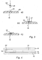
- FIG. 1 shows an insulating glazing consisting of two outer glass panes 12 and 14.
- the disc 14 forms the outer cover of a photovoltaic module 16.
- the inner cover forms the disc 15. Between the discs 15, 16, the solar cells are arranged.
- a contact strip 18 is arranged in the photovoltaic module 16 as an electrical connection.
- the contact strip 18 is guided through a hole in the inner cover 15 into the space between the panes 20.
- a commercially available spacer 22 is provided, through which the electrical connection from the space between the panes 20 can be led to the outside and there with an electrical connection element 26, usually a external cable, can be brought into contact.
- the space between the panes 20 is filled with gas, as is the case with insulating glazings. The electrical connection must therefore be gas and vapor-tight.
- the spacers 22 are made of aluminum hollow profile elements, which are made by plastic fasteners 28, as in FIG. 2 are shown, connected by an aluminum hollow profile is pushed onto both sides of a connecting element 28 and held there by frictional engagement.
- the connecting elements 28 have a Bore 30 on.
- connection element 28 is provided with a stepped hole 30, this being in representation a) of FIG. 2 can be seen.
- Presentation a) of FIG. 2 shows the corresponding connecting element 28 in section and the bottom thereof. In the direction of arrow 32, the hollow profiles of the spacer 22 are pushed onto the connecting element 28.
- FIG. b) it is now shown how a special sealing nipple 34 made of elastic material with integrated threaded nut 36 is inserted into the stepped bore 30.
- a threaded bolt 38 which is shown in representation c) clamped by screwing with the integrated threaded nut 36 on the one hand, the sealing nipple 34 with the shaft of the threaded bolt 38 and on the other hand with the connecting element 28 gas-tight.
- a commercial cable lug 40 is fastened to the threaded bolt 38, which serves for making electrical contact with a contact strip 18 of the photovoltaic module 16.
- the thus equipped connecting element 28 is installed in the insulating glass spacer 22, wherein a connecting element 28 per contact strip 18 is used.
- the contact points are first recessed or provided with a suitable cover.
- the external connecting cable is now electrical Connection element 42, which is also provided with a cable lug 44, fixed by means of a threaded nut 46 on the threaded bolt 38.
- electrical Connection element 42 which is also provided with a cable lug 44, fixed by means of a threaded nut 46 on the threaded bolt 38.
- connection After mounting the external connection cable, the connection is sealed with sealant and thus also electrically insulated.
- non-electrically conductive washers are additionally used under the cable lugs 44, 40 in order to avoid that when mating the spacer profiles 22, which may consist of a metallic material, with the connecting elements 28 an electrical contact between bolts 38 and spacer profiles 22 occurs, which could cause a short circuit.
- FIG. 3 shows now three illustration a) to c) of a further variant of the electrical contacting, wherein like parts are to be provided here with the same reference numerals.
- a bore 30 is again provided in the connecting element 28, through which the contact strip 18 is threaded.
- the bolt used here is a blind rivet 48, under the head 50 of which a cable lug 44 is pushed.
- the cable lug 44 is in turn connected to the electrical connection element 42.
- the blind rivet 48 is from the outside inserted into the hole 30 and there, as shown in the illustrations b) and c) attached.
- the cable lug 44 which surrounds the blind rivet 48 is fixed under the head 50 of the blind rivet 48 and at the same time the contact band 18 is clamped between the wall of the bore 30 and the rivet 48.
- the contact strip 18 is directly contacted with the electrical connection 42 via the cable lug 44 and, as can be seen well in illustration c), the bore 30 is closed. On the electrical conductivity of the bolt or blind rivet it does not matter then.
- this solution has the advantage that the assembly of the rivet 48 can take place only after the assembly of the insulating glass pane.
- the holes 30 can then simultaneously serve as Gasbehellö réelle the insulating glass.
- FIG. 1 be provided to provide two holes, wherein the contact strip 18 is led out through a first hole 30 from the disc space 20, wherein the hole 30 completely penetrates the spacer 22 and after passing the contact strip 18 is closed with a stopper, and next to a second hole provided is, which is formed from the outside of the spacer ago 22 in particular as a blind hole.
- this second hole can then, as analogous to FIG. 4 described, the determination of the ribbon 18 and the contacting done.
- FIG. 4 shows a variant of the invention, in which the contact strip 18 is brought from the outside to the electrical connection.
- the spacer 22 is disposed between the inner module cover 15 and the glass sheet 12.
- the cable ribbon exits between the inner 15 and the outer module cover 14, and is determined analogously to the above-described definition "from the outside" in the spacer 22.
- the protruding ribbon 18 is thereby pushed back into the hole or folded folded on the back of the spacer 22.
Landscapes
- Securing Of Glass Panes Or The Like (AREA)
- Joining Of Glass To Other Materials (AREA)
- Photovoltaic Devices (AREA)
- Insulating Bodies (AREA)
- Liquid Crystal (AREA)
Description
- Die Erfindung betrifft eine Photovoltaik-Isolierverglasung umfassend eine mehrschichtige Verglasung mit einem Photovoltaik-Modul, wobei Kontaktbändchen zur Kontaktierung des Photovoltaik-Moduls aus dem Photovoltaik-Modul herausgeführt sind und wobei ein Abstandshalter zur Beabstandung der Glasschichten zur Bildung des Zwischenraums vorgesehen ist, der z. B. aus einer Profilschiene gebildet ist, wobei in dem Abstandshalter mindestens eine Öffnung vorgesehen ist, mittels derer das Kontaktbändchen und ein elektrisches Anschlusselement über einen Bolzen, der in die Öffnung eingesetzt ist, festgelegt sind und wobei das Kontaktbändchen mit dem außerhalb der Glasschichten vorgesehenen elektrischen Anschlusselement zusammenwirkt.
- Die Verwendung von Photovoltaik-Modulen in Isolierverglasungen erfolgt über eine Glasschicht z. B. aus einem Doppelglas, in das die Solarzellen eingebettet bzw. auf das sie aufgebracht sind. Dieses Modul stellt in der Regel die eine Schicht der Isolierverglasung. Die andere wird durch eine Glasscheibe gebildet. Zwischen Glasscheibe und Photovoltaik-Modul besteht ein Scheibenzwischenraum, der zur Bildung einer Isolierverglasung mit Gas befüllbar ist. Eine solche Anordnung ist z. B. aus der
EP 199 233 A1 - Zur Herstellung von Photovoltaik-Isolierverglasungen ist es notwendig, eine elektrische Verbindung zwischen dem Photovoltaik-Modul der Isolierverglasung und der Außenseite der Isolierverglasung herzustellen. Insbesondere wenn Photovoltaik-Module verarbeitet werden, bei denen die elektrischen Anschlüsse, die sogenannten "Kontaktbändchen", durch Lochbohrungen der rückseitigen Modulabdeckung aus dem Photovoltaik-Modul austreten, bestehen Probleme, da dieses Kontaktbändchen dadurch innerhalb des Scheibenzwischenraums der Isolierverglasung verläuft. Die Kontaktbändchen bestehen hierbei aus einem dünnen Metallband. Die elektrische Anbindung an die externen Anschlüsse muss insbesondere folgende Anforderungen erfüllen:
- Gas- und Wasserdampfdichtigkeit,
- Zugentlastung der Modulanschlüsse,
- rückseitig geringe Bauhöhe von maximal 5 mm entsprechend der üblichen Dichtstoffüberdeckung eines Isolierglases,
- Kabelaustritt möglichst tangential zum Isolierglasrand,
- der Montageablauf muss sich optimal in die Isolierglasfertigung integrieren lassen.
- Es ist neben der Lösung der
EP 199 233 A1 - Eine weitere Lösung des elektrischen Anschlusses zeigt
US-PS 4,832,755 . - Es ist daher Aufgabe der vorliegenden Erfindung, eine Photovoltaik-Isolierverglasung bereitzustellen, bei der die elektrischen Anschlüsse auf einfache Weise mit den Kontaktbändchen verbunden sind und die oben genannten Anforderungen erfüllt werden.
- Die Erfindung löst diese Aufgabe durch eine Photovoltaik-Isolierverglasung mit den Merkmalen des Anspruchs 1.
- Dabei erfolgt die Herausführung des Kontaktbändchen aus dem Photovoltaik-Modul seitlich aus den Modulschichten. Der Abstandshalter kann dann entweder zwischen der inneren Modulabdeckung und der Glasscheibe oder zwischen der äußeren Modulabdeckung und der Glasscheibe angeordnet sein.
- Sofern die Anordnung des Abstandshalters nach der zweiten Alternative erfolgt, muss die innere Modulabdeckung gegenüber der äußeren gekürzt sein. Die Festlegung des Kontaktbändchens erfolgt jedoch, wie nachstehend beschrieben.
- Erfolgt die Anordnung des Abstandshalters nach der ersten Alternative, so tritt das Kontaktbändchen nicht in den Scheibenzwischenraum aus, sondern tritt ganz außerhalb der Isolierverglasung zutage. Die Festlegung erfolgt dann ebenfalls wie die des externen Anschlusselements "von außen", entweder durch Festlegung über einen Kabelschuh oder Einklemmen desselben zwischen Bohrungswandung und Bolzen.
- Es ist dann besonders vorteilhaft, dass die Bohrung im Abstandshalter und/oder dem Verbinder nicht bis in den Scheibenzwischenraum durchgeht, sondern lediglich die äußere Seite eine Öffnung besitzt. Die Dichtigkeit des Scheibenzwischenraums wird dann nicht beeinträchtigt. Das Kontaktbändchen wird dann schließlich ebenfalls durch die Isolierung bei der fertigen Scheibe umschlossen.
- Besonders vorteilhaft ist dabei, dass der elektrische Anschluss hierbei beim eingebauten bzw. schon bereits fertigen Fenster nicht mehr gesehen werden kann, da keine Bohrungen vorgenommen werden müssen, die in den Scheibenzwischenraum hineinragen.
- Der Abstandshalter kann dabei einzelne Elemente sowie Verbindungselemente umfassen, wobei die einzelnen Elemente über die Verbindungselemente verbunden sind, wobei die Öffnungen dann Bohrungen in den Verbindungselementen sein können. Bei den Verbindungselementen kann es sich um handelsübliche Linear- oder Eckverbinder für Isolierglasabstandshalter mit Lochbohrung handeln, so dass kein zusätzlicher Herstellungsaufwand entsteht.
- Alternativ kann in dem Abstandshalter selber eine oder mehrerer Bohrungen vorgesehen sein.
- Es kann dabei vorgesehen sein, dass die Bohrung zugleich auch als Gasbefüllöffnung für das Isolierglas dient.
- Es kann insbesondere vorgesehen sein, dass die Bohrung ein Gewinde aufweist und der Bolzen in sie hineingeschraubt ist. Wahlweise kann der Bolzen jedoch auch in die Bohrung hineingepresst werden.
- Nach einer ersten Alternative kann vorgesehen sein, dass sich das Kontaktbändchen durch die Bohrung erstreckt und durch das Gewinde des Bolzens geklemmt wird.
- Als elektrisches Anschlusselement kann hier beispielsweise ein Anschlusskabel mit einem Kabelschuh dienen, wobei das Kontaktbändchen mit dem Kabelschuh in direkter Verbindung steht. Der Bolzen kann hierbei beispielsweise eine Mutter aufweisen, bzw. einen Bolzenkopf, durch den der Kabelschuh zwischen der Wandung des Verbindungselementes und/oder des Abstandhalters und dem Kopf des Bolzens geklemmt und damit kraftschlüssig gehalten wird. Hierdurch wird das externe Anschlusselement festgelegt. Das Kontaktbändchen und damit der Modulanschluss selbst ist dann zugentlastet und die Öffnung im Abstandshalter und/oder Verbindungselement wird gleichzeitig verschlossen, so daß das in die Isolierglasscheibe eingefüllte Gas im Scheibenzwischenraum gehalten wird.
- Je nach Ausgestaltung können die Bolzen aus elektrisch leitendem oder nichtleitendem Material bestehen und unterschiedliche Ausführungsformen, wie z. B. Blindniet, Spreizmuffe oder ähnliches aufweisen.
- Nach einem weiteren Ausführungsbeispiel kann vorgesehen sein, dass in der Bohrung ein elastischer Dichtnippel vorgesehen ist, um den Glasscheibenzwischenraum gegenüber der Außenseite der Glasschichten abzudichten. Auf diese Weise kann die Gas-und Dampfdichtheit noch besser gewährleistet werden.
- Die Verbinder können dabei aus Kunststoff bestehen. Es kann vorgesehen sein, dass die Abstandshalter, die aus beispielsweise Aluminiumhohlprofilen gebildet sind, auf die Verbinder aufgeschoben und dort verklemmt werden. Insbesondere kann hierbei eine Presspassung vorgesehen sein. Als elektrisches Anschlusselement kann ein Kabelschuh vorgesehen sein, an dem ein Anschlusskabel angebracht ist.
- Sofern die Abstandshalter aus elektrisch leitendem Material bestehen, kann vorgesehen sein, dass nicht leitfähige Unterlegscheiben verwendet werden, um einen elektrischen Kontakt zwischen dem Bolzen und den Abstandsprofilen und dadurch Kurzschlüsse zu vermeiden.
- Sofern die Öffnungen in dem Abstandshalterprofil selbst vorgesehen sind, ist eine elektrische Isolierung stets notwendig, sofern diese aus leitendem Material bestehen. Bei Kunststoffhohlprofilen kann hierauf verzichtet werden.
- Um zu verhindern, dass die Anschlusskabel, die den Dichtstoff des Isolierglases schräg nach außen durchdringen, beim Ziehen am Anschlusskabel aus dem Dichtstoff herausgerissen werden können, bis zu der Stelle, an der der Kabelschuh mit dem Bolzen am Abstandshalter befestigt ist, wodurch das Photovoltaik-Isolierglas zerstört werden kann, kann vorgesehen sein, an der Stelle des Kabelaustritts einen Klotz, z. B. aus Kunststoff, vorzusehen, der ungefähr die Breite des Isolierglases aufweist, d. h. eine Breite umfasst, die in etwa der Breite der Glasscheiben, die den Scheibenzwischenraum zwischen sich einschließen, sowie des Scheibenzwischenraums selber entspricht. Dieser Klotz kann dann auf den noch nicht ausgehärteten Isolierglasdichtstoff aufgeklebt werden. Hierbei kann ein üblicher Verglasungsklotz mit vorzugsweise 0,5 bis 8 mm Dicke vorgesehen sein, der neben seiner Schutzfunktion für den Kabelaustritt auch gleichzeitig als Verglasungsklotz dienen kann.
- Durch einen derartigen Klotz kann darüber hinaus auch verhindert werden, dass die Anschlusskabel beim Einbau zwischen Unterkonstruktion und Glas nicht eingequetscht werden.
- Ein derartiger Klotz kann nutenförmige Aussparungen längs der Glaskante zur Aufnahme des Kabels aufweisen, die den zusätzlichen Vorteil einer erhöhten Dichtstoffüberdeckung im Bereich des elektrischen Anschlusses bieten. Darüber hinaus kann der Klotz an seiner dem Glas zugewandten Seite Überstände in Form von beispielsweise Widerhaken aufweisen, die sich bei Aufkleben des Klotzes in den Dichtstoff drücken und nach Aushärten des Dichtstoffes zu einem zusätzlichen Formschluss zwischen Klotz und Dichtstoff führen.
- Die Bohrungen können dabei Stufenbohrungen sein.
- Die Erfindung soll im Folgenden anhand von Ausführungsbeispielen näher erläutert werden.
- Dabei zeigen:
- Figur 1:
- eine Photovoltaik-Isolierverglasung;
- Figur 2:
- die Montage des elektrischen Anschlusses nach einer ersten Ausgestaltung;
- Figur 3:
- eine zweite Ausgestaltung eines elektrischen Anschlusses; und
- Figur 4
- eine erfindungsgemäße Ausgestaltung einer PV- Isolierverglasung.
-
Figur 1 zeigt eine Isolierverglasung bestehend aus zwei äußeren Glasscheiben 12 und 14. Die Scheibe 14 bildet dabei die äußere Abdeckung eines Photovoltaik-Moduls 16. Die innere Abdeckung bildet die Scheibe 15. Zwischen den Scheiben 15, 16 sind die Solarzellen angeordnet. - Zur elektrischen Kontaktierung ist in dem Photovoltaik-Modul 16 als elektrischer Anschluss ein Kontaktbändchen 18 angeordnet. Das Kontaktbändchen 18 ist dabei durch eine Bohrung in der inneren Abdeckung 15 in den Scheibenzwischenraum 20 geführt.
- Zur Bildung eines Scheibenzwischenraums 20 zwischen der Scheibe 15 und der Glasscheibe 12, der eine Isolierfunktion erfüllt, ist ein handelsüblicher Abstandshalter 22 vorgesehen, durch den der elektrische Anschluss aus dem Scheibenzwischenraum 20 nach außen geführt werden kann und dort mit einem elektrischen Anschlusselement 26, zumeist einem externen Kabel, in Kontakt gebracht werden kann. Der Scheibenzwischenraum 20 ist dabei wie bei Isolierverglasungen üblich gasgefüllt. Der elektrische Anschluss muss daher gas- und dampfdicht sein.
- Die Abstandshalter 22 bestehen aus Aluminiumhohlprofilelementen, die durch Verbindungselemente 28 aus Kunststoff, wie sie in
Figur 2 gezeigt sind, verbunden werden, indem auf beide Seiten eines Verbindungselementes 28 ein Aluminiumhohlprofil aufgeschoben und dort reibschlüssig gehalten ist. Die Verbindungselemente 28 weisen dabei eine Bohrung 30 auf. - Zur elektrischen Kontaktierung der Photovoltaik-Module 16 kann nun vorgesehen sein, dass das Verbindungselement 28 mit einer stufenförmigen Lochbohrung 30 versehen ist, wobei dies in Darstellung a) von
Figur 2 zu ersehen ist. Darstellung a) vonFigur 2 zeigt das entsprechende Verbindungselement 28 im Schnitt sowie die Unterseite desselben. In Pfeilrichtung 32 werden auf das Verbindungselement 28 die Hohlprofile des Abstandshalters 22 aufgeschoben. - In Darstellung b) wird nun gezeigt, wie ein spezieller Dichtnippel 34 aus elastischem Material mit integrierter Gewindemutter 36 in die Stufenbohrung 30 eingesteckt wird. Ein Gewindebolzen 38, der in Darstellung c) gezeigt ist, verklemmt durch Verschraubung mit der integrierten Gewindemutter 36 einerseits den Dichtnippel 34 mit dem Schaft des Gewindebolzens 38 und andererseits mit dem Verbindungselement 28 gasdicht.
- Während des Verschraubens wird ein handelsüblicher Kabelschuh 40 an dem Gewindebolzen 38 befestigt, der zur elektrischen Kontaktierung eines Kontaktbändchens 18 des Photovoltaik-Moduls 16 dient. Das so ausgestattete Verbindungselement 28 wird in den Isolierglasabstandshalter 22 eingebaut, wobei ein Verbindungselement 28 pro Kontaktbändchen 18 verwendet wird.
- Bei der Isolierglasproduktion selbst, d. h. dem Zusammenfügen der einzelnen Scheiben, ist als zusätzlicher Produktionsschritt damit lediglich die Klemmverbindung zwischen Kontaktbändchen und Kabelschuh herzustellen. Bei der Versiegelung des Isolierglases werden die Kontaktstellen zunächst ausgespart bzw. mit einer geeigneten Abdeckung versehen.
- Im eingebauten Zustand wird nun, wie in Darstellung d) gezeigt ist, das externe Anschlusskabel als elektrisches Anschlusselement 42, das ebenfalls mit einem Kabelschuh 44 versehen ist, mittels einer Gewindemutter 46 an dem Gewindebolzen 38 festgelegt. Auf diese Weise wird eine gasdichte elektrische Verbindung zwischen dem Kontaktbändchen 18 und dem elektrischen Anschlusselement 42 über den Bolzen 38 sichergestellt.
- Zugkräfte auf das elektrische Anschlusselement 42 werden in das Verbindungselement 28 und nicht in das Kontaktbändchen 18 eingeleitet, so dass dieses von Zugbelastungen frei ist. Darüber hinaus ist die Gas- und Wasserdampfdichtigkeit sichergestellt und der Glaszwischenraum 20 ist unabhängig von Umgebungseinflüssen.
- Nach der Montage des externen Anschlusskabels wird der Anschluss mit Dichtstoff versiegelt und damit auch elektrisch isoliert.
- Darüber hinaus werden zusätzlich nicht elektrisch leitfähige Unterlegscheiben unter den Kabelschuhen 44, 40 verwendet, um zu vermeiden, dass beim Zusammenstecken der Abstandshalterprofile 22, die aus einem metallischen Material bestehen können, mit den Verbindungselementen 28 ein elektrischer Kontakt zwischen Bolzen 38 und Abstandshalterprofilen 22 auftritt, der einen Kurzschluss verursachen könnte.
-
Figur 3 zeigt nun drei Darstellung a) bis c) einer weiteren Variante der elektrischen Kontaktierung, wobei gleiche Teile hier mit gleichen Bezugszeichen versehen sein sollen. - In dem Verbindungselement 28 ist hierbei wiederum eine Bohrung 30 vorgesehen, durch die das Kontaktbändchen 18 hindurchgefädelt wird. Als Bolzen dient hier ein Blindniet 48, unter dessen Kopf 50 ein Kabelschuh 44 geschoben wird. Der Kabelschuh 44 ist wiederum mit dem elektrischen Anschlusselement 42 verbunden. Der Blindniet 48 wird von außen in die Lochbohrung 30 eingesteckt und dort, wie in den Darstellungen b) und c) gezeigt ist, befestigt.
- Hierbei wird der Kabelschuh 44, der den Blindniet 48 umgreift unter dem Kopf 50 des Blindniets 48 festgelegt und gleichzeitig das Kontaktbändchen 18 zwischen der Wandung der Bohrung 30 und dem Niet 48 eingeklemmt. Eine Übertragung von Zugkräften wirkt danach nicht länger auf das Kontaktbändchen 18. Darüber hinaus wird hierbei das Kontaktbändchen 18 mit dem elektrischen Anschluss 42 über den Kabelschuh 44 direkt kontaktiert und, wie gut in Darstellung c) gesehen werden kann, die Bohrung 30 verschlossen. Auf die elektrische Leitfähigkeit des Bolzens bzw. Blindniets kommt es dann nicht an.
- Gegenüber der in
Figur 2 gezeigten Alternative besitzt diese Lösung den Vorteil, dass die Montage der Niete 48 erst nach dem Zusammenbau der Isolierglasscheibe erfolgen kann. Die Lochbohrungen 30 können dann gleichzeitig als Gasbefüllöffnung des Isolierglases dienen. - Alternativ kann bei einem Aufbau wie bei
Figur 1 vorgesehen sein, zwei Bohrungen vorzusehen, wobei das Kontaktbändchen 18 über eine erste Lochbohrung 30 aus dem Scheibenzwischenraum 20 herausgeführt wird, wobei die Lochbohrung 30 den Abstandshalter 22 vollständig durchdringt und nach Durchführung das Kontaktbändchen 18 mit einem Stopfen verschlossen wird, und daneben eine zweite Bohrung vorgesehen ist, die von der Außenseite des Abstandshalters her 22 insbesondere als Sackloch ausgebildet ist. In dieser zweiten Bohrung kann dann, wie analog zuFigur 4 beschrieben, die Festlegung des Bändchens 18 und die Kontaktierung erfolgen. -
Figur 4 zeigt nun eine erfindungsgemäße Variante, bei der das Kontaktbändchen 18 von außen an den elektrischen Anschluss herangeführt ist. - Hierbei ist der Abstandshalter 22 zwischen der inneren Modulabdeckung 15 und der Glasscheibe 12 angeordnet. Das Kabelbändchen tritt zwischen innerer 15 und äußerer Modulabdeckung 14, aus und wird analog zu der zuvor beschriebenen Festlegung nun "von außen" in dem Abstandshalter 22 festgelegt.
- Um einen sicheren Kontakt zwischen Kontaktbändchen 18 und Kabelschuh 44 sicherzustellen, können diese auch miteinander verlötet werden. Um dabei eine Schädigung des Abstandshalters 22 zu verhindern, insbesondere wenn dieser aus Kunststoff besteht, sollte das Verlöten vorzugsweise vor der Befestigung des Kabelschuhs 44 und des Bändchens 18 mit dem Bolzen geschehen. Dabei ergibt sich vorteilhafterweise folgender Montageablauf:
- Sofern erforderlich (
Figur 1 ) wird das Bändchen 18 durch die Lochbohrung 30 hindurchgeführt, so dass es einige Zentimeter nach außen hinausragt. - Das Bändchen 18 wird im Abstand von einigen Zentimetern vom Abstandshalter 22 an den Kabelschuh 44 des elektrischen Anschlusskabels 26 gelötet.
- Der Kabelschuh 44 mit dem angelöteten Bändchen 18 wird mit dem Bolzen am Abstandshalter 22 festgelegt.
- Das überstehende Bändchen 18 wird dabei in die Lochbohrung zurückgeschoben oder zusammengefaltet auf den Rücken des Abstandshalters 22 gelegt.
- Weitere Vorteile und Merkmale ergeben sich aus den übrigen Anmeldungsunterlagen.
Claims (12)
- Photovoltaik-Isolierverglasung umfassend eine mehrschichtige Verglasung (12, 14, 15) mit einem Photovoltaik-Modul (16), wobei Kontaktbändchen (18) zur Kontaktierung des Photovoltaik-Moduls (16) aus dem Photovoltaik-Modul (16) herausgeführt sind, und ein Abstandshalter (22) zur Beabstandung der Glasschichten (12, 14, 15) zur Bildung eines Scheibenzwischenraums (20) vorgesehen ist, wobei in dem Abstandshalter (22) mindestens eine Öffnung (30) vorgesehen ist, mittels derer das Kontaktbändchen (18) und ein elektrisches Anschlusselement (42, 26) über einen Bolzen (38, 48), der in die Öffnung (30) eingesetzt ist, festgelegt sind und wobei die Kontaktbändchen (18) mit dem außerhalb der Glasschichten (12, 14) vorgesehenen elektrischen Anschlusselement (42, 26) zusammenwirken, dadurch gekennzeichnet, dass der Abstandshalter (22) lediglich an seiner Außenseite eine Öffnung aufweist und das Kontaktbändchen (18) seitlich aus dem Photovoltaik-Modul herausgeführt ist und von außen mittels einem Bolzen (38, 48) in der Öffnung festgelegt ist.
- Photovoltaik-Isolierverglasung nach Anspruch 1, dadurch gekennzeichnet, dass der Abstandshalter (22) mehrere Elemente und Verbindungselemente umfasst, wobei die einzelnen Elemente des Abstandshalters (22) über die Verbindungselemente (28) verbunden sind und in den Verbindungselementen (28) die Öffnungen (30) vorgesehen sind.
- Photovoltaik-Isolierverglasung nach einem oder mehreren der vorangehenden Ansprüche, dadurch gekennzeichnet, dass in der Öffnung (30) ein elastischer Dichtnippel (3.4) vorgesehen ist, der insbesondere eine Gewindemutter (36) beinhaltet, zur Abdichtung des Glasscheibenzwischenraums (20) gegenüber der Außenseite der Glasschichten (12, 14).
- Photovoltaik-Isolierverglasung nach einem oder mehreren der vorangehenden Ansprüche, dadurch gekennzeichnet, dass das Verbindungselement (28) aus Kunststoff besteht.
- Photovoltaik-Isolierverglasung nach einem oder mehreren der vorangehenden Ansprüche, dadurch gekennzeichnet, dass die Elemente des Abstandshalters (22) auf die Verbindungselemente (28) aufgeschoben und dort verklemmt sind.
- Photovoltaik-Isolierverglasung nach einem oder mehreren der vorangehenden Ansprüche, dadurch gekennzeichnet, dass die Verbindungselemente Linear- und/oder Eckverbindungselemente (28) sind.
- Photovoltaik-Isolierverglasung nach einem oder mehreren der vorangehenden Ansprüche, dadurch gekennzeichnet, dass das elektrische Anschlusselement (26, 42) und/oder das Kontaktbändchen (18) mit einem Kabelschuh (44) verbunden sind.
- Photovoltaik-Isolierverglasung nach einem oder mehreren der vorangehenden Ansprüche, dadurch gekennzeichnet, dass die Abstandshalterelemente (22) aus elektrisch leitenden Profilen bestehen.
- Photovoltaik-Isolierverglasung nach einem oder mehreren der vorangehenden Ansprüche, dadurch gekennzeichnet, dass nicht leitfähige Unterlegscheiben vorgesehen sind; um einen elektrischen Kontakt zwischen Bolzen (38) und Abstandsprofilen (22) zu verhindern.
- Photovoltaik-Isolierverglasung nach einem oder mehreren der vorangehenden Ansprüche, dadurch gekennzeichnet, dass die Öffnung (30) eine Stufenbohrung ist.
- Photovoltaik-Isolierverglasung nach einem oder mehreren der vorangehenden Ansprüche, dadurch gekennzeichnet, dass die Bohrung ein Gewinde aufweist und der Bolzen, der als Gewindebolzen ausgebildet ist, hierin einschraubbar ist.
- Photovoltaik-Isolierverglasung nach einem oder mehreren der vorangehenden Ansprüche, dadurch gekennzeichnet, dass der Bolzen (38) ein Blindniet (48) ist.
Applications Claiming Priority (3)
| Application Number | Priority Date | Filing Date | Title |
|---|---|---|---|
| DE10146498A DE10146498C2 (de) | 2001-09-21 | 2001-09-21 | Photovoltaik-Isolierverglasung |
| DE10146498 | 2001-09-21 | ||
| PCT/EP2002/010620 WO2003028114A2 (de) | 2001-09-21 | 2002-09-20 | Photovoltaik-isolieverglasung |
Publications (2)
| Publication Number | Publication Date |
|---|---|
| EP1428265A2 EP1428265A2 (de) | 2004-06-16 |
| EP1428265B1 true EP1428265B1 (de) | 2008-08-06 |
Family
ID=7699751
Family Applications (1)
| Application Number | Title | Priority Date | Filing Date |
|---|---|---|---|
| EP02777171A Expired - Lifetime EP1428265B1 (de) | 2001-09-21 | 2002-09-20 | Photovoltaik-isolierverglasung |
Country Status (7)
| Country | Link |
|---|---|
| US (1) | US7834265B2 (de) |
| EP (1) | EP1428265B1 (de) |
| JP (1) | JP2005504441A (de) |
| AT (1) | ATE403939T1 (de) |
| DE (2) | DE10146498C2 (de) |
| ES (1) | ES2311630T3 (de) |
| WO (1) | WO2003028114A2 (de) |
Cited By (1)
| Publication number | Priority date | Publication date | Assignee | Title |
|---|---|---|---|---|
| EP4455442A2 (de) | 2023-04-28 | 2024-10-30 | Küster Holding GmbH | Isolierglasanordnung mit intergriertem solarpanel |
Families Citing this family (20)
| Publication number | Priority date | Publication date | Assignee | Title |
|---|---|---|---|---|
| DE10361184B3 (de) * | 2003-12-24 | 2005-02-03 | Glaswerke Arnold Gmbh & Co. Kg | Photovoltaik-Isolierglasscheibe |
| DE102006007472B4 (de) | 2006-02-17 | 2018-03-22 | Fraunhofer-Gesellschaft zur Förderung der angewandten Forschung e.V. | Photovoltaisches Konzentratormodul mit Multifunktionsrahmen |
| WO2009108385A2 (en) * | 2008-02-28 | 2009-09-03 | Epv Solar, Inc. | Insulating glass unit with integrated mini-junction device |
| DE102008019703C5 (de) * | 2008-04-18 | 2024-02-15 | Harrexco Ag | Verfahren und Vorrichtung zum Durchführen einer elektrischen Isolationsprüfung an Photovoltaikmodulen |
| DE102008030652A1 (de) | 2008-06-27 | 2009-12-31 | Dracowo Forschungs- Und Entwicklungs Gmbh | Stoffe und Verfahren zur Herstellung Photovoltaik aktiver Fassadenelemente |
| BE1020124A3 (fr) * | 2011-07-20 | 2013-05-07 | Agc Glass Europe | Panneau de vitrage isolant comprenant au moins un espace interne comprenant un lame d'un gaz isolant. |
| WO2013038409A2 (en) * | 2011-09-12 | 2013-03-21 | Pythagoras Solar Inc. | Electrical joint |
| JP5746957B2 (ja) * | 2011-12-02 | 2015-07-08 | 株式会社エクソル | 太陽電池モジュールの架台支持構造 |
| FI20116266A7 (fi) * | 2011-12-13 | 2013-06-14 | Kone Corp | Eristetty hissin tason ovi |
| US20130319598A1 (en) | 2012-05-30 | 2013-12-05 | Cardinal Ig Company | Asymmetrical insulating glass unit and spacer system |
| US20140021903A1 (en) * | 2012-07-18 | 2014-01-23 | Veka Inc. | Windows and doors having integrated solar powered charging devices |
| EP2706306B1 (de) | 2012-09-07 | 2016-05-18 | ODB-Tec GmbH & Co.KG | Isolierglasanordnung und Verfahren zu seiner Herstellung |
| WO2014086552A1 (en) * | 2012-12-03 | 2014-06-12 | Kingspan Holdings (Irl) Limited | A composite insulating panel |
| US10763778B2 (en) * | 2015-12-09 | 2020-09-01 | Brian Patrick Janowski | Solar window construction and methods |
| US11489483B2 (en) | 2015-12-09 | 2022-11-01 | Brian Patrick Janowski | Solar window construction and methods |
| US10211776B2 (en) * | 2015-12-09 | 2019-02-19 | Brian Patrick Janowski | Solar window construction and methods |
| DE202024002540U1 (de) | 2023-03-17 | 2025-06-05 | Saint-Gobain Sekurit France | Photovoltaische Verbundscheibe mit einer Aerogel-Lage |
| WO2024251445A1 (de) | 2023-06-05 | 2024-12-12 | Saint-Gobain Glass France | Photovoltaische fahrzeugscheibe mit vakuumisolierung |
| EP4474144A1 (de) | 2023-06-05 | 2024-12-11 | Autoglas D & K B.V. | Photovoltaische verbundscheibe mit evakuierter aerogel-lage |
| WO2025021739A1 (de) | 2023-07-25 | 2025-01-30 | Saint-Gobain Glass France | Verfahren zur herstellung einer verbundscheibe mit photovoltaikmodul |
Family Cites Families (38)
| Publication number | Priority date | Publication date | Assignee | Title |
|---|---|---|---|---|
| JPS5328751B2 (de) * | 1974-11-27 | 1978-08-16 | ||
| US4083097A (en) * | 1976-11-30 | 1978-04-11 | The United States Of America As Represented By The Administrator Of The National Aeronautics And Space Administration | Method of making encapsulated solar cell modules |
| CH616203A5 (en) * | 1977-03-11 | 1980-03-14 | Giesbrecht Alfred Wwe Soehne | Insulating glass pane |
| GB1554507A (en) * | 1977-04-28 | 1979-10-24 | Tideland Signal Corp | Enclosure for solar cells |
| FR2423621A1 (fr) * | 1978-04-17 | 1979-11-16 | Saint Gobain | Entree de fils electriques a l'interieur d'un vitrage multiple |
| BE876681A (fr) * | 1978-06-14 | 1979-11-30 | Bfg Glassgroup | Procede de fabrication d'un panneau comprenant au moins une cellule photovoltaique et panneau comprenant au moins une telle cellule |
| US4167644A (en) * | 1978-09-29 | 1979-09-11 | Exxon Research & Engineering Co. | Solar cell module |
| DE3014246C2 (de) * | 1980-04-14 | 1983-05-19 | Bfg Glassgroup, Paris | Isolierglaseinheit |
| US4401839A (en) * | 1981-12-15 | 1983-08-30 | Atlantic Richfield Company | Solar panel with hardened foil back layer |
| US4582953A (en) * | 1983-06-24 | 1986-04-15 | Kyocera Corporation | Solar cell module |
| DE3330305A1 (de) * | 1983-08-23 | 1985-03-14 | Rainer 6072 Dreieich Bauer | Fenster |
| EP0199233B1 (de) | 1985-04-17 | 1990-01-31 | Siemens Aktiengesellschaft | Bauelement für den Hochbau und seine Verwendung |
| US4607132A (en) * | 1985-08-13 | 1986-08-19 | Jarnagin William S | Integrated PV-thermal panel and process for production |
| DE3674002D1 (de) * | 1986-06-23 | 1990-10-11 | Alsacienne Emaillerie | Fassadenplatte aus glas. |
| US4832755A (en) * | 1987-08-11 | 1989-05-23 | The Boeing Company | Glass encapsulation of solar cell arrays to minimize voltage/plasma interaction effects in a space environment |
| DE3903521C2 (de) * | 1989-02-07 | 1993-11-25 | Kunert Heinz | Transparentes Element zur Verwendung als Fenster-, Wand, Dach- oder Brüstungselement |
| US5167724A (en) * | 1991-05-16 | 1992-12-01 | The United States Of America As Represented By The United States Department Of Energy | Planar photovoltaic solar concentrator module |
| DE4128766C2 (de) * | 1991-08-29 | 1995-07-20 | Flachglas Ag | Solarmodul sowie Verfahren zu dessen Herstellung |
| DE4227860A1 (de) * | 1991-09-19 | 1993-04-01 | Aug Guttendoerfer Gmbh & Co | Photovoltaische platte, insbesondere zum einsatz als fassadenplatte |
| DE4300480A1 (de) * | 1993-01-11 | 1994-07-14 | Kunert Heinz | Sicherheitsglaselement mit Wärmedämmeigenschaften |
| DE4301128A1 (de) * | 1993-01-18 | 1994-07-21 | Schueco Int Kg | Fassadenelement |
| EP0615045A1 (de) * | 1993-03-12 | 1994-09-14 | Peter Lisec | Anordnung zum elektrisch leitenden Verbinden |
| US5460660A (en) * | 1993-07-21 | 1995-10-24 | Photon Energy, Inc. | Apparatus for encapsulating a photovoltaic module |
| US5589006A (en) * | 1993-11-30 | 1996-12-31 | Canon Kabushiki Kaisha | Solar battery module and passive solar system using same |
| DE19508222C1 (de) * | 1995-03-08 | 1996-06-05 | Siemens Ag | Optoelektronischer Wandler und Herstellverfahren |
| ATA90695A (de) | 1995-05-30 | 1998-08-15 | Lisec Peter | Isolierglasscheibe mit fotovoltaischem element |
| FR2752012B3 (fr) * | 1996-07-31 | 1998-08-21 | Saint Gobain Vitrage | Procede pour realiser le vide entre deux feuilles de verre et vitrage isolant |
| FR2762039B1 (fr) * | 1997-04-11 | 1999-06-04 | Saint Gobain Vitrage | Element vitre a haut pouvoir isolant |
| US6262358B1 (en) * | 1999-02-18 | 2001-07-17 | Sharp Kabushiki Kaisha | Solar cell module and solar cell panel using the same |
| US6311455B1 (en) * | 1999-10-01 | 2001-11-06 | Odl, Incorporated | Insulated glass spacer with integral muntin |
| DE29924398U1 (de) * | 1999-12-07 | 2003-02-06 | SAINT-GOBAIN GLASS Deutschland GmbH, 52066 Aachen | Bauelement mit einer Leitungsdurchführung |
| FR2815374B1 (fr) * | 2000-10-18 | 2003-06-06 | Saint Gobain | Vitrage feuillete et ses moyens d'etancheification peripherique |
| US6589613B1 (en) * | 2000-11-20 | 2003-07-08 | Heinz Kunert | Insulating glass element for glazing a building |
| JP4076742B2 (ja) * | 2001-07-13 | 2008-04-16 | シャープ株式会社 | 太陽電池モジュール |
| US6646196B2 (en) * | 2001-11-26 | 2003-11-11 | Apogee Enterprises, Inc. | Window structure with photovoltaic panel |
| US6793971B2 (en) * | 2001-12-03 | 2004-09-21 | Cardinal Ig Company | Methods and devices for manufacturing insulating glass units |
| GB2385086B (en) * | 2002-02-12 | 2005-10-12 | Torgut Tony Munir | A seal for an evacuated window |
| DE20302045U1 (de) * | 2003-02-10 | 2003-07-10 | Wulfmeier Solar GmbH, 33609 Bielefeld | Photovoltaik-Module mit PVB (Polyvinyl-Butyral)-Folie |
-
2001
- 2001-09-21 DE DE10146498A patent/DE10146498C2/de not_active Expired - Fee Related
-
2002
- 2002-09-20 US US10/490,144 patent/US7834265B2/en not_active Expired - Fee Related
- 2002-09-20 DE DE50212608T patent/DE50212608D1/de not_active Expired - Lifetime
- 2002-09-20 AT AT02777171T patent/ATE403939T1/de active
- 2002-09-20 EP EP02777171A patent/EP1428265B1/de not_active Expired - Lifetime
- 2002-09-20 ES ES02777171T patent/ES2311630T3/es not_active Expired - Lifetime
- 2002-09-20 WO PCT/EP2002/010620 patent/WO2003028114A2/de not_active Ceased
- 2002-09-20 JP JP2003531537A patent/JP2005504441A/ja active Pending
Cited By (2)
| Publication number | Priority date | Publication date | Assignee | Title |
|---|---|---|---|---|
| EP4455442A2 (de) | 2023-04-28 | 2024-10-30 | Küster Holding GmbH | Isolierglasanordnung mit intergriertem solarpanel |
| DE102023111089A1 (de) | 2023-04-28 | 2024-10-31 | Küster Holding Gesellschaft mit beschränkter Haftung | Isolierglasanordnung |
Also Published As
| Publication number | Publication date |
|---|---|
| WO2003028114A3 (de) | 2003-09-25 |
| US7834265B2 (en) | 2010-11-16 |
| EP1428265A2 (de) | 2004-06-16 |
| JP2005504441A (ja) | 2005-02-10 |
| WO2003028114A2 (de) | 2003-04-03 |
| US20050034754A1 (en) | 2005-02-17 |
| ES2311630T3 (es) | 2009-02-16 |
| DE50212608D1 (de) | 2008-09-18 |
| DE10146498C2 (de) | 2003-11-20 |
| ATE403939T1 (de) | 2008-08-15 |
| DE10146498A1 (de) | 2003-04-24 |
Similar Documents
| Publication | Publication Date | Title |
|---|---|---|
| EP1428265B1 (de) | Photovoltaik-isolierverglasung | |
| DE10361184B3 (de) | Photovoltaik-Isolierglasscheibe | |
| DE102009012539A1 (de) | Verbindungsvorrichtung zum Anschluss an ein Solarmodul und Solarmodul mit einer solchen Verbindungsvorrichtung | |
| EP3743584A1 (de) | Abstandhalter für isolierverglasungen mit integriertem flachbandkabel | |
| EP0867946A2 (de) | Photovoltaisches Solarmodul in Plattenform | |
| DE29605510U1 (de) | Photovoltaisches Solarmodul in Plattenform | |
| DE102012010277A1 (de) | Elektrisches Verbindungssystem | |
| DE10249992C1 (de) | Durchsichtige Scheibe mit einer undurchsichtigen Kontaktfläche für eine Lötverbindung | |
| WO2014009491A1 (de) | Kantenverbinder für photovoltaische solarmodule | |
| EP4101030B1 (de) | Flachleiteranschlusselement | |
| EP2605280A1 (de) | Metallisches Bauelement oder Flacherzeugnis mit photovoltaisch wirksamer Beschichtung, Verfahren zu dessen Herstellung und aus solchen, miteinander elektrisch verschalteten Bauelementen gebildete Verkleidung | |
| EP4183970A2 (de) | Stromabführungssystem für eine beschattungseinrichtung und beschattungseinrichtung hierfür | |
| EP3361036A1 (de) | Modul zur energieübertragung | |
| DE60018359T2 (de) | Bauelement mit einer Kabeldurchführung sowie Herstellungsverfahren für dasselbe | |
| EP0475417A2 (de) | Anordnung von Führungselementen für elektrische Leitungen im Fassadenbereich von Gebäuden | |
| EP0609651B1 (de) | Fassadenelement | |
| EP3743582A1 (de) | Isolierverglasung, fenster und verfahren zur herstellung | |
| EP4080757B1 (de) | Anschlussdose für das anschliessen von elektrischen leitern an ein photovoltaikmodul | |
| EP2339646B1 (de) | Solarmodul, Anschlussdose, Solarmodulverbinderanordnung, Verfahren und Verwendung | |
| EP3743581A1 (de) | Isolierverglasung und fenster | |
| DE102012111440A1 (de) | Fenster, Tür oder Fassadenelement mit einer Isolierleiste mit integriertem Leuchtmittel | |
| EP2811239B1 (de) | Distanzhalter | |
| DE102024116271B3 (de) | Lamelle einer Beschattungseinrichtung sowie Beschattungseinrichtung und Verfahren zum Befestigen eines Klammerelementes an einer Lamelle | |
| DE19748868C1 (de) | Isolierglasscheibe mit elektrischer Leiterschleife | |
| DE10319607B3 (de) | Korrosionsschutzschaltung für eine Leiterstruktur auf einer Antennenscheibe, Verfahren zum Betreiben einer aktiven Antennenscheibe und Antennenscheibe für Fahrzeuge |
Legal Events
| Date | Code | Title | Description |
|---|---|---|---|
| PUAI | Public reference made under article 153(3) epc to a published international application that has entered the european phase |
Free format text: ORIGINAL CODE: 0009012 |
|
| 17P | Request for examination filed |
Effective date: 20040303 |
|
| AK | Designated contracting states |
Kind code of ref document: A2 Designated state(s): AT BE BG CH CY CZ DE DK EE ES FI FR GB GR IE IT LI LU MC NL PT SE SK TR |
|
| RIN1 | Information on inventor provided before grant (corrected) |
Inventor name: SCHMIDT, CHRISTOPH |
|
| 17Q | First examination report despatched |
Effective date: 20060810 |
|
| GRAP | Despatch of communication of intention to grant a patent |
Free format text: ORIGINAL CODE: EPIDOSNIGR1 |
|
| GRAS | Grant fee paid |
Free format text: ORIGINAL CODE: EPIDOSNIGR3 |
|
| GRAA | (expected) grant |
Free format text: ORIGINAL CODE: 0009210 |
|
| AK | Designated contracting states |
Kind code of ref document: B1 Designated state(s): AT BE BG CH CY CZ DE DK EE ES FI FR GB GR IE IT LI LU MC NL PT SE SK TR |
|
| REG | Reference to a national code |
Ref country code: GB Ref legal event code: FG4D Free format text: NOT ENGLISH |
|
| REG | Reference to a national code |
Ref country code: CH Ref legal event code: EP |
|
| REG | Reference to a national code |
Ref country code: IE Ref legal event code: FG4D Free format text: LANGUAGE OF EP DOCUMENT: GERMAN |
|
| REF | Corresponds to: |
Ref document number: 50212608 Country of ref document: DE Date of ref document: 20080918 Kind code of ref document: P |
|
| REG | Reference to a national code |
Ref country code: CH Ref legal event code: NV Representative=s name: MICHELI & CIE SA |
|
| REG | Reference to a national code |
Ref country code: GR Ref legal event code: EP Ref document number: 20080402987 Country of ref document: GR |
|
| PG25 | Lapsed in a contracting state [announced via postgrant information from national office to epo] |
Ref country code: NL Free format text: LAPSE BECAUSE OF FAILURE TO SUBMIT A TRANSLATION OF THE DESCRIPTION OR TO PAY THE FEE WITHIN THE PRESCRIBED TIME-LIMIT Effective date: 20080806 |
|
| REG | Reference to a national code |
Ref country code: ES Ref legal event code: FG2A Ref document number: 2311630 Country of ref document: ES Kind code of ref document: T3 |
|
| PG25 | Lapsed in a contracting state [announced via postgrant information from national office to epo] |
Ref country code: FI Free format text: LAPSE BECAUSE OF FAILURE TO SUBMIT A TRANSLATION OF THE DESCRIPTION OR TO PAY THE FEE WITHIN THE PRESCRIBED TIME-LIMIT Effective date: 20080806 |
|
| REG | Reference to a national code |
Ref country code: IE Ref legal event code: FD4D |
|
| PG25 | Lapsed in a contracting state [announced via postgrant information from national office to epo] |
Ref country code: MC Free format text: LAPSE BECAUSE OF NON-PAYMENT OF DUE FEES Effective date: 20080930 Ref country code: IE Free format text: LAPSE BECAUSE OF FAILURE TO SUBMIT A TRANSLATION OF THE DESCRIPTION OR TO PAY THE FEE WITHIN THE PRESCRIBED TIME-LIMIT Effective date: 20080806 Ref country code: DK Free format text: LAPSE BECAUSE OF FAILURE TO SUBMIT A TRANSLATION OF THE DESCRIPTION OR TO PAY THE FEE WITHIN THE PRESCRIBED TIME-LIMIT Effective date: 20080806 Ref country code: BG Free format text: LAPSE BECAUSE OF FAILURE TO SUBMIT A TRANSLATION OF THE DESCRIPTION OR TO PAY THE FEE WITHIN THE PRESCRIBED TIME-LIMIT Effective date: 20081106 |
|
| PG25 | Lapsed in a contracting state [announced via postgrant information from national office to epo] |
Ref country code: CZ Free format text: LAPSE BECAUSE OF FAILURE TO SUBMIT A TRANSLATION OF THE DESCRIPTION OR TO PAY THE FEE WITHIN THE PRESCRIBED TIME-LIMIT Effective date: 20080806 Ref country code: SK Free format text: LAPSE BECAUSE OF FAILURE TO SUBMIT A TRANSLATION OF THE DESCRIPTION OR TO PAY THE FEE WITHIN THE PRESCRIBED TIME-LIMIT Effective date: 20080806 Ref country code: PT Free format text: LAPSE BECAUSE OF FAILURE TO SUBMIT A TRANSLATION OF THE DESCRIPTION OR TO PAY THE FEE WITHIN THE PRESCRIBED TIME-LIMIT Effective date: 20090106 |
|
| PLBE | No opposition filed within time limit |
Free format text: ORIGINAL CODE: 0009261 |
|
| STAA | Information on the status of an ep patent application or granted ep patent |
Free format text: STATUS: NO OPPOSITION FILED WITHIN TIME LIMIT |
|
| 26N | No opposition filed |
Effective date: 20090507 |
|
| PG25 | Lapsed in a contracting state [announced via postgrant information from national office to epo] |
Ref country code: EE Free format text: LAPSE BECAUSE OF FAILURE TO SUBMIT A TRANSLATION OF THE DESCRIPTION OR TO PAY THE FEE WITHIN THE PRESCRIBED TIME-LIMIT Effective date: 20080806 |
|
| PG25 | Lapsed in a contracting state [announced via postgrant information from national office to epo] |
Ref country code: SE Free format text: LAPSE BECAUSE OF FAILURE TO SUBMIT A TRANSLATION OF THE DESCRIPTION OR TO PAY THE FEE WITHIN THE PRESCRIBED TIME-LIMIT Effective date: 20081106 |
|
| PG25 | Lapsed in a contracting state [announced via postgrant information from national office to epo] |
Ref country code: CY Free format text: LAPSE BECAUSE OF FAILURE TO SUBMIT A TRANSLATION OF THE DESCRIPTION OR TO PAY THE FEE WITHIN THE PRESCRIBED TIME-LIMIT Effective date: 20080806 Ref country code: LU Free format text: LAPSE BECAUSE OF NON-PAYMENT OF DUE FEES Effective date: 20080920 |
|
| PG25 | Lapsed in a contracting state [announced via postgrant information from national office to epo] |
Ref country code: TR Free format text: LAPSE BECAUSE OF FAILURE TO SUBMIT A TRANSLATION OF THE DESCRIPTION OR TO PAY THE FEE WITHIN THE PRESCRIBED TIME-LIMIT Effective date: 20080806 |
|
| PGFP | Annual fee paid to national office [announced via postgrant information from national office to epo] |
Ref country code: GB Payment date: 20100831 Year of fee payment: 9 Ref country code: GR Payment date: 20100922 Year of fee payment: 9 |
|
| PGFP | Annual fee paid to national office [announced via postgrant information from national office to epo] |
Ref country code: BE Payment date: 20100921 Year of fee payment: 9 |
|
| BERE | Be: lapsed |
Owner name: GLASWERKE ARNOLD G.M.B.H. & CO. KG Effective date: 20110930 |
|
| GBPC | Gb: european patent ceased through non-payment of renewal fee |
Effective date: 20110920 |
|
| REG | Reference to a national code |
Ref country code: GR Ref legal event code: ML Ref document number: 20080402987 Country of ref document: GR Effective date: 20120403 |
|
| PG25 | Lapsed in a contracting state [announced via postgrant information from national office to epo] |
Ref country code: BE Free format text: LAPSE BECAUSE OF NON-PAYMENT OF DUE FEES Effective date: 20110930 |
|
| PG25 | Lapsed in a contracting state [announced via postgrant information from national office to epo] |
Ref country code: GR Free format text: LAPSE BECAUSE OF NON-PAYMENT OF DUE FEES Effective date: 20120403 Ref country code: GB Free format text: LAPSE BECAUSE OF NON-PAYMENT OF DUE FEES Effective date: 20110920 |
|
| PGFP | Annual fee paid to national office [announced via postgrant information from national office to epo] |
Ref country code: AT Payment date: 20130927 Year of fee payment: 12 Ref country code: ES Payment date: 20130927 Year of fee payment: 12 Ref country code: CH Payment date: 20130926 Year of fee payment: 12 |
|
| PGFP | Annual fee paid to national office [announced via postgrant information from national office to epo] |
Ref country code: IT Payment date: 20130927 Year of fee payment: 12 |
|
| PGFP | Annual fee paid to national office [announced via postgrant information from national office to epo] |
Ref country code: FR Payment date: 20130926 Year of fee payment: 12 Ref country code: DE Payment date: 20131121 Year of fee payment: 12 |
|
| REG | Reference to a national code |
Ref country code: DE Ref legal event code: R119 Ref document number: 50212608 Country of ref document: DE |
|
| REG | Reference to a national code |
Ref country code: CH Ref legal event code: PL |
|
| REG | Reference to a national code |
Ref country code: AT Ref legal event code: MM01 Ref document number: 403939 Country of ref document: AT Kind code of ref document: T Effective date: 20140920 |
|
| REG | Reference to a national code |
Ref country code: FR Ref legal event code: ST Effective date: 20150529 |
|
| PG25 | Lapsed in a contracting state [announced via postgrant information from national office to epo] |
Ref country code: DE Free format text: LAPSE BECAUSE OF NON-PAYMENT OF DUE FEES Effective date: 20150401 Ref country code: LI Free format text: LAPSE BECAUSE OF NON-PAYMENT OF DUE FEES Effective date: 20140930 Ref country code: CH Free format text: LAPSE BECAUSE OF NON-PAYMENT OF DUE FEES Effective date: 20140930 |
|
| PG25 | Lapsed in a contracting state [announced via postgrant information from national office to epo] |
Ref country code: AT Free format text: LAPSE BECAUSE OF NON-PAYMENT OF DUE FEES Effective date: 20140920 Ref country code: FR Free format text: LAPSE BECAUSE OF NON-PAYMENT OF DUE FEES Effective date: 20140930 Ref country code: IT Free format text: LAPSE BECAUSE OF NON-PAYMENT OF DUE FEES Effective date: 20140920 |
|
| REG | Reference to a national code |
Ref country code: ES Ref legal event code: FD2A Effective date: 20160601 |
|
| PG25 | Lapsed in a contracting state [announced via postgrant information from national office to epo] |
Ref country code: ES Free format text: LAPSE BECAUSE OF NON-PAYMENT OF DUE FEES Effective date: 20140921 |