EP1427987B1 - Capteur de vitesse gyroscopique vibrant - Google Patents
Capteur de vitesse gyroscopique vibrant Download PDFInfo
- Publication number
- EP1427987B1 EP1427987B1 EP02755327A EP02755327A EP1427987B1 EP 1427987 B1 EP1427987 B1 EP 1427987B1 EP 02755327 A EP02755327 A EP 02755327A EP 02755327 A EP02755327 A EP 02755327A EP 1427987 B1 EP1427987 B1 EP 1427987B1
- Authority
- EP
- European Patent Office
- Prior art keywords
- mode
- resonator
- axis
- response
- ring
- Prior art date
- Legal status (The legal status is an assumption and is not a legal conclusion. Google has not performed a legal analysis and makes no representation as to the accuracy of the status listed.)
- Expired - Lifetime
Links
- 230000000295 complement effect Effects 0.000 description 13
- 238000000034 method Methods 0.000 description 10
- 230000000694 effects Effects 0.000 description 8
- 238000000926 separation method Methods 0.000 description 6
- 238000004519 manufacturing process Methods 0.000 description 5
- 239000000463 material Substances 0.000 description 5
- 238000009966 trimming Methods 0.000 description 4
- 238000004458 analytical method Methods 0.000 description 3
- 239000000758 substrate Substances 0.000 description 3
- XUIMIQQOPSSXEZ-UHFFFAOYSA-N Silicon Chemical compound [Si] XUIMIQQOPSSXEZ-UHFFFAOYSA-N 0.000 description 2
- 239000004020 conductor Substances 0.000 description 2
- 239000010410 layer Substances 0.000 description 2
- 238000003754 machining Methods 0.000 description 2
- 239000002184 metal Substances 0.000 description 2
- 229910052751 metal Inorganic materials 0.000 description 2
- 230000003287 optical effect Effects 0.000 description 2
- 230000010355 oscillation Effects 0.000 description 2
- 230000035945 sensitivity Effects 0.000 description 2
- 229910052710 silicon Inorganic materials 0.000 description 2
- 239000010703 silicon Substances 0.000 description 2
- 230000002411 adverse Effects 0.000 description 1
- 230000003321 amplification Effects 0.000 description 1
- 238000010276 construction Methods 0.000 description 1
- 230000008878 coupling Effects 0.000 description 1
- 238000010168 coupling process Methods 0.000 description 1
- 238000005859 coupling reaction Methods 0.000 description 1
- 230000007423 decrease Effects 0.000 description 1
- 230000009977 dual effect Effects 0.000 description 1
- 230000003628 erosive effect Effects 0.000 description 1
- 239000011521 glass Substances 0.000 description 1
- 230000001939 inductive effect Effects 0.000 description 1
- 230000003993 interaction Effects 0.000 description 1
- 150000002739 metals Chemical class 0.000 description 1
- 238000003199 nucleic acid amplification method Methods 0.000 description 1
- 239000002344 surface layer Substances 0.000 description 1
- 238000012876 topography Methods 0.000 description 1
Images


Classifications
-
- G—PHYSICS
- G01—MEASURING; TESTING
- G01C—MEASURING DISTANCES, LEVELS OR BEARINGS; SURVEYING; NAVIGATION; GYROSCOPIC INSTRUMENTS; PHOTOGRAMMETRY OR VIDEOGRAMMETRY
- G01C19/00—Gyroscopes; Turn-sensitive devices using vibrating masses; Turn-sensitive devices without moving masses; Measuring angular rate using gyroscopic effects
- G01C19/56—Turn-sensitive devices using vibrating masses, e.g. vibratory angular rate sensors based on Coriolis forces
- G01C19/567—Turn-sensitive devices using vibrating masses, e.g. vibratory angular rate sensors based on Coriolis forces using the phase shift of a vibration node or antinode
- G01C19/5677—Turn-sensitive devices using vibrating masses, e.g. vibratory angular rate sensors based on Coriolis forces using the phase shift of a vibration node or antinode of essentially two-dimensional vibrators, e.g. ring-shaped vibrators
Definitions
- This invention relates to rate sensors for sensing applied rate about two axes.
- the devices described in GB 2335273 make use of a single out of plane cosN c ⁇ vibration mode (where N c is the mode order) in combination with a degenerate pair of in plane sin (N c ⁇ 1) ⁇ /cos (N c ⁇ 1) ⁇ vibrations modes.
- the out of plane cosN c ⁇ mode acts as the primary carrier mode which is typically maintained at a fixed vibration amplitude.
- Coriolis forces are induced which couple energy into the in plane sin (N c ⁇ 1) ⁇ /cos (N c ⁇ 1) ⁇ modes.
- the amplitude of the induced in plane response mode motion is directly proportional to the applied rotation rate.
- the two axis rate sensor designs described in GB 2318184 make use of a single in plane cosN c ⁇ vibration mode in combination with a degenerate pair of out of plane sin (N c ⁇ 1) ⁇ /cos (N c ⁇ 1) ⁇ vibration modes.
- the in plane cosN c ⁇ mode acts as the primary carrier mode which is typically maintained at a fixed vibration amplitude.
- Coriolis forces are induced which couple energy into the out of plane sin (N c ⁇ 1) ⁇ /cos (N c ⁇ 1) ⁇ modes.
- the amplitude of the induced out of plane response mode motion is directly proportional to the applied rotation rate.
- WO-A-0155675 A further two axis rate sensor design is shown in WO-A-0155675 which is intended to be operated with a sin3 ⁇ /cos3 ⁇ vibration mode pair providing degenerate carrier and response parameters.
- the carrier and the two response mode frequencies are required to be nominally identical. With these frequencies accurately matched the amplitude of the response mode vibration is amplfied by the mechanical quality factor, Q, of the structure. This inevitably makes the construction tolerances more stringent. In practice, it may be necessary to fine-tune the balance of the vibrating structure or resonator by adding or removing material at appropriate points. This adjusts the stiffness of mass parameters for the modes and thus differentially shifts the mode frequencies. Where these frequencies are not matched the Q amplification does not occur and the pick-offs must be made sufficiently sensitive to provide adequate gyroscope performance.
- any given pair of in or out of plane sinN ⁇ /cosN ⁇ modes will have identical frequencies for any value of N.
- This degeneracy may be perturbed due to the requirement for the leg structures which support the ring. These have the effect of point spring masses acting at the point of attachment to the ring which will alter the modal mass and stiffness.
- N R is the response mode order.
- These legs are set at an angular separation of 90°/N R .
- the resonator dimensions are set in order to match the carrier mode frequency to that of the response mode pair. Matching of the frequency of the second complementary mode of the carrier mode pair is not required.
- These support legs have a linear part 9' attached to the inner circumference of the ring 5 extending radially towards a central boss 20, a second linear part 9" extending from the central boss 20 and radially displaced from the first part.
- the first and second part are connected by an arcuate section 9"' concentric with the ring 5.
- the three parts will be integrally formed. It will be understood by those skilled in the art that other leg designs can be employed (e.g. S shaped or C shaped structures) which provide the same function in supporting the ring structure. Additionally these legs may be attached either internally or externally to the ring structure.
- the radial and tangential stiffness of the legs should be significantly lower than that of the ring itself so that the modal vibration is dominated by the ring structure.
- the radial stiffness is largely determined by the length of the arcuate segment 9"' of the leg.
- the straight segments 9' and 9" of the leg dominate the tangential stiffness.
- the overall length of the leg structure largely determines the out of plane stiffness. Maintaining the ring to leg compliance ratio, particularly for the radial stiffness, for this design of leg becomes increasingly difficult as the arc angle of the leg structure is restricted by the proximity of the adjacent legs.
- the structures described in the prior art may be fabricated in a variety of materials using a number of processes. Where such devices are fabricated from metal these may be conveniently machined to high precision using wire erosion techniques to achieve the accurate dimensional tolerancing required. This process involves sequentially machining away material around the edges of each leg and the ring structure. The machining time, and hence production cost, increases in proportion to the number of legs. The number of legs hitherto thought to be required increases rapidly with mode order. Minimising the number of legs is therefore highly desirable, particularly for designs employing higher order modes. Similar considerations apply to structures fabricated from other materials using alternative processes.
- a two axis gyroscope including a substantially planar vibrator resonator having a substantially ring or hoop-like structure with inner and outer peripheries extending around a common axis, carrier mode drive means for causing the resonator to vibrate in a cosN ⁇ vibration mode, carrier mode pick-off means for sensing movement of the resonator in response to said carrier mode drive means, x-axis response mode pick-off means for detecting movement of the resonator in response to rotation about the x-axis, x-axis response mode drive means for nulling said motion, y-axis response mode pick-off means for detecting movement of the resonator in response to rotation about the y-axis, y-axis response mode drive means for nulling said motion, and support means for flexibly supporting the resonator and for allowing the resonator to vibrate relative to the support means in response to the drive means and to applied rotation
- L N c / K , where K is an integer and L>2 and N is the carrier mode order, thereby to fix the carrier mode orientation on the ring or hoop-like structure, and wherein L ⁇ 4 x N R , where N R is the response mode order.
- a desired large fixed frequency split may be provided between the cosN c ⁇ carrier mode and its complementary sinN c ⁇ mode thus fixing its orientation on the ring structure. This may be achieved whilst maintaining the dynamic symmetry of the sin (N c ⁇ 1) ⁇ /cos (N c ⁇ 1) ⁇ response mode pair such that their frequencies are matched.
- the number of support leg structures may also be reduced.
- Each leg may comprise first and second linear portions extending from opposite ends of an arcuate portion.
- the legs are substantially equi-angularly spaced.
- the support means includes a base having a projecting boss, with the inner periphery of the substantially ring or hoop-like structure to the projecting boss so that the ring or hoop-like structure is spaced from the base.
- the total stiffness of the legs is less than that of the ring or hoop-like structure.
- the formulae defined above have been obtained as a result of a detailed analysis of the dynamics of the ring or hoop-like structure including the effects of leg motion.
- the present invention may provide increased design flexibility allowing greater leg compliance (relative to the ring) whilst employing increased leg dimensions (in the plane of the ring). Such designs may exhibit reduced sensitivity to dimensional tolerancing effects and allow more economical fabrication.
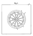
- the vibrating structure 5 has a substantially planar substantially ring-like shape having an outer rim 7, legs 9 and a central hub or boss 20 as previously described.
- the structure 5 is located via the boss 20 on an insulating substrate layer 10 which may be made of glass or silicon with an insulating oxide surface layer.
- the vibrating structure 5 is maintained at a fixed voltage with respect to all the conductors which act as the drive and pick-off elements.
- means for vibrating the silicon vibrating structure 5 in a cos2 ⁇ carrier mode includes two electrostatic carrier drive elements 22 and two electrostatic carrier mode pick-off elements 23 arranged with the drive elements 22 at 0° and 180° and the pick-off elements 23 at 90° and 270° respectively with respect to the outer rim 7 of the vibrating structure 5 and located radially externally of the outer rim 7 adjacent the points of maximum radial motion of the rim 7 when vibrating in the cos2 ⁇ mode.
- These carrier mode drive elements 22 are used to set the vibrating structure 5 into oscillation.
- the carrier mode pick-off elements 23 which are located at the carrier mode anti-nodal points, sense the radial motion of the vibrating structure 5.
- the drive elements may be electromagnetic, electrostatic, piezo, thermal or optical in actuation and the vibrating structure 5 motion may be detected using electrostatic, electromagnetic, piezor or optical techniques.
- the means for detecting the rocking mode vibration includes an x axis electrostatic drive element 24, an x axis electrostatic pick-off element 25 located adjacent the outer rim 7 in superimposed relationship therewith at a perpendicular spacing therefrom with the y axis drive element 26, the x axis pick-off element 25, the y axis pick-off element 27 and the x axis drive element 24 being arranged at 0° 90°, 180° and 270° respectively around the outer rim 7.
- the rocking motion of the x axis rate response mode is detected at the pick-off element 25 located on the surface of the support substrate under the rim 7.
- This motion is nulled using the x axis drive element 24 similarly located under the opposite side of the rim 7.
- the y axis rate response motion is similarly detected by pick-off element 27 and nulled by drive element 26.
- the various drive and pick-off conductive sites are connected, via tracking 28 laid onto the substrate layer surface 21, to bond pads 29.
- the drive and pick-off circuitry is then connected to these bond pads.
- a cross-section of the sensor of Figure 2 is shown in Figure 3 . This shows the topography of the in plane and surface conductors more clearly.
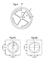
- the required mode splitting may be achieved using four support legs at 90° separation as shown in Figure 4 .
- Two axis rate sensors may be designed using either of these mode pairs as response modes.
- the points of attachment of the legs to the ring will align directly with the radial anti-nodes of one mode and will coincide with the radial nodes of the complementary mode.
- Figures 5A and 5B The resulting alignment of the in-plane sin2 ⁇ /cos2 ⁇ modes with respect to the resonator structure are shown in Figures 5A and 5B where the 0° angle corresponds to the 0° reference, R, in Figure 4 .
- the points of attachment of the legs will coincide with anti-nodes of the out of plane motion of one mode and the nodes of the complementary mode.
- Figures 6A and 6B show the resulting alignment of the out of plane sin2 ⁇ /cos2 ⁇ modes with respect to the resonator structure.
- the matching of the carrier mode frequency with the desired sin (N c ⁇ 1) ⁇ /cos (N c ⁇ 1) ⁇ response mode frequencies is typically achieved by adjusting the depth (z-axis dimension) of the ring. This shifts the frequencies of the out of plane modes but leaves the in plane mode frequencies substantially constant.
- the required mode splitting may be achieved using three support legs with 120° separation or with six support legs at 60° separation as show in Figures 7 and 8 respectively.
- the points of attachment of the legs to the ring will align directly with the radial anti-nodes of one mode and will coincide with the radial nodes of the complementary mode.
- the required mode splitting may be achieved by four support legs at 90° separation or with eight support legs at 45° separation as shown in Figures 11 and 12 .
- the points of attachment of the legs to the ring will align directly with the radial anti-nodes of one mode and will coincide with the radial nodes of the complementary mode.
- Figures 14A and 14B show the resulting alignment for the out of plane cos4 ⁇ /sin4 ⁇ modes with respect to the resonator structure.
- the drive and pick-off elements are conveniently located directly above and/or below the anti-nodes of the out of plane motion.
- the drive and pick-off elements are conveniently located adjacent to the radial anti-nodes in the plane of the ring.
- the optimum alignment for the drive and pick-off elements is therefore achieved without the requirement for any trimming or adjustment of the mode positions.
- tolerancing affects in the fabrication process may lead to small imbalances in cosN R ⁇ mode frequencies. These may be corrected, using mechanical trimming techniques such as described in GB-A-2292609 which describes a trimming procedure suitable for use with in plane sinN R ⁇ /cosN R ⁇ modes. It is likely that such techniques will need to be applied to the response modes for two axis devices. Due to the large imbalance between the carrier mode and its compliment for the structures described here, the mode alignment will be unaffected by such trimming procedures.
- the resonator designs shown in Figures 4 , 7 , 8 , 11 and 12 provide structures suitable for use in two axis rate sensors. These designs provide a carrier mode whose position is fixed with respect to the resonator structure which is isolated in frequency from its complementary mode. This is generally achieved using a number of support leg structures which is reduced from those of the prior art. This provides increased design flexibility allowing the ratio between the combined leg stiffness and the ring stiffness to be maintained at required value using increased leg dimensions (in the plane of the ring). Such designs exhibit reduced sensitivity to dimensional tolerancing effects and allow for more economical fabrication, particularly for structures machined from metals.
- the combined stiffness of the support legs is required to be less than that of the ring. This ensures that the modal vibration is dominated by the ring structure and helps to isolate the resonator from the effects of thermally induced stresses coupling in via the boss 20 of the structure, which will adversely affect performance.
- the required leg to ring compliance ratio may be maintained by using longer support leg structures of increased width.
Claims (6)
- Gyroscope à deux axes, englobant un résonateur vibratoire pratiquement plan (5), comportant une structure de forme pratiquement annulaire ou circulaire, avec des périphéries interne et externe (6, 7) s'étendant autour d'un axe commun (8), un moyen d'entraînement de mode porteur (22) pour entraîner la vibration du résonateur dans un mode de vibration cos NCθ, un moyen de détection du mode porteur (23) pour détecter le mouvement du résonateur en réponse audit moyen d'entraînement de mode porteur, un moyen de détection du mode de réponse de l'axe X (25) pour détecter le mouvement du résonateur en réponse à la rotation autour de l'axe X, un moyen d'entraînement du mode de réponse de l'axe X (24) pour annuler ledit mouvement, un moyen de détection du mode de réponse de l'axe y (27) pour détecter le mouvement du résonateur (5) en réponse à la rotation autour de l'axe y, un moyen d'entraînement du mode de réponse de l'axe y (26) pour annuler ledit mouvement, et un moyen de support (9) pour supporter de manière flexible le résonateur (5) et pour permettre la vibration du résonateur (5) par rapport au moyen de support (9) en réponse au moyen d'entraînement (22) et à la rotation appliquée, caractérisé en ce que le moyen de support (9) comprend 4 branches, l'ordre du mode porteur Nc correspondant à 2 et l'ordre du mode de réponse hors du plan NR correspondant à 3, fixant ainsi l'orientation du mode porteur sur la structure annulaire ou circulaire.
- Gyroscope à deux axes, englobant un résonateur vibratoire pratiquement plan (5), comportant une structure de forme pratiquement annulaire ou circulaire, avec des périphéries interne et externe (6, 7) s'étendant autour d'un axe commun (8), un moyen d'entraînement de mode porteur (22) pour entraîner la vibration du résonateur dans le mode de vibration cosNCθ, un moyen de détection du mode porteur (23) pour détecter le mouvement du résonateur en réponse audit moyen d'entraînement de mode porteur, un moyen de détection du mode de réponse de l'axe X (25) pour détecter le mouvement du résonateur en réponse à la rotation autour de l'axe X, un moyen d'entraînement de mode de réponse de l'axe X (24) pour annuler ledit mouvement, un moyen de détection du mode de réponse de l'axe y (27) pour détecter le mouvement du résonateur (5) en réponse à la rotation autour de l'axe y, un moyen d'entraînement du mode de réponse de l'axe y (26) pour annuler ledit mouvement, et un moyen de support (9) pour supporter de manière flexible le résonateur (5) et pour permettre la vibration du résonateur (5) par rapport au moyen de support (9) en réponse au moyen d'entraînement (22) et à la rotation appliquée, caractérisé en ce que le moyen de support (9) comprend 3 ou 6 branches, l'ordre du mode porteur dans le plan Nc correspondant à 3 et l'ordre du mode de réponse hors du plan NR correspondant à 2 ou 4, fixant ainsi l'orientation du mode porteur sur la structure de forme annulaire ou circulaire.
- Capteur de vitesse selon les revendications 1 ou 2, dans lequel chaque branche (9) comprend des première et deuxième parties linéaires (91, 911) s'étendant à partir des extrémités opposées d'une partie arquée (9111).
- Capteur de vitesse selon l'une quelconque des revendications précédentes, dans lequel les branches sont espacées pratiquement à angles égaux.
- Capteur de vitesse selon l'une quelconque des revendications précédentes, dans lequel le moyen de support englobe une base, comportant un bossage en saillie (20), la périphérie interne (6) de la structure de forme pratiquement annulaire ou circulaire étant accouplée au bossage (20) par les branches (9) s'étendant de ladite périphérie interne (6) de la structure de forme annulaire ou circulaire vers le bossage en saillie (20), de sorte que la structure de forme annulaire ou circulaire est espacée de la base
- Capteur de vitesse selon l'une quelconque des revendications précédentes, dans lequel la rigidité totale des branches est inférieure à celle de la structure de forme annulaire ou circulaire.
Applications Claiming Priority (3)
| Application Number | Priority Date | Filing Date | Title |
|---|---|---|---|
| GBGB0122256.1A GB0122256D0 (en) | 2001-09-14 | 2001-09-14 | Vibratory gyroscopic rate sensor |
| GB0122256 | 2001-09-14 | ||
| PCT/GB2002/004056 WO2003025503A1 (fr) | 2001-09-14 | 2002-09-06 | Capteur de vitesse gyroscopique vibrant |
Publications (2)
| Publication Number | Publication Date |
|---|---|
| EP1427987A1 EP1427987A1 (fr) | 2004-06-16 |
| EP1427987B1 true EP1427987B1 (fr) | 2012-04-04 |
Family
ID=9922111
Family Applications (1)
| Application Number | Title | Priority Date | Filing Date |
|---|---|---|---|
| EP02755327A Expired - Lifetime EP1427987B1 (fr) | 2001-09-14 | 2002-09-06 | Capteur de vitesse gyroscopique vibrant |
Country Status (9)
| Country | Link |
|---|---|
| US (1) | US6978674B2 (fr) |
| EP (1) | EP1427987B1 (fr) |
| JP (1) | JP4774497B2 (fr) |
| KR (1) | KR20040031091A (fr) |
| CN (1) | CN1610819A (fr) |
| AT (1) | ATE552474T1 (fr) |
| CA (1) | CA2458601A1 (fr) |
| GB (1) | GB0122256D0 (fr) |
| WO (1) | WO2003025503A1 (fr) |
Families Citing this family (20)
| Publication number | Priority date | Publication date | Assignee | Title |
|---|---|---|---|---|
| US7437253B2 (en) * | 2004-07-29 | 2008-10-14 | The Boeing Company | Parametrically disciplined operation of a vibratory gyroscope |
| US7434465B1 (en) * | 2006-08-07 | 2008-10-14 | Litton Systems Inc. | Ring resonator gyroscope with cylindrical ring suspension |
| JP5142623B2 (ja) * | 2007-08-10 | 2013-02-13 | 住友精密工業株式会社 | 2次元光走査装置 |
| US7992438B2 (en) * | 2007-11-28 | 2011-08-09 | Chung Shan Institute Of Science And Technology, Armaments Bureau, M.N.D. | Multiaxial gyroscope |
| CN101910790A (zh) * | 2008-01-29 | 2010-12-08 | 住友精密工业株式会社 | 使用压电体膜的振动陀螺仪及其制造方法 |
| WO2009119205A1 (fr) | 2008-03-25 | 2009-10-01 | 住友精密工業株式会社 | Gyroscope vibratoire utilisant un film piézoélectrique |
| US8375792B2 (en) | 2008-03-25 | 2013-02-19 | Sumitomo Precision Products Co., Ltd. | Vibratory gyroscope using piezoelectric film |
| CN102246003B (zh) | 2008-12-09 | 2015-09-09 | 株式会社村田制作所 | 振动陀螺仪元件及其制造方法 |
| JP5523755B2 (ja) * | 2009-02-11 | 2014-06-18 | 住友精密工業株式会社 | 圧電体膜を用いた振動ジャイロ及びその製造方法 |
| US9091544B2 (en) * | 2010-11-05 | 2015-07-28 | Analog Devices, Inc. | XY-axis shell-type gyroscopes with reduced cross-talk sensitivity and/or mode matching |
| US9709595B2 (en) | 2013-11-14 | 2017-07-18 | Analog Devices, Inc. | Method and apparatus for detecting linear and rotational movement |
| US9599471B2 (en) | 2013-11-14 | 2017-03-21 | Analog Devices, Inc. | Dual use of a ring structure as gyroscope and accelerometer |
| CN103629229A (zh) * | 2013-11-18 | 2014-03-12 | 华南理工大学 | 一种半环片环形均布的大柔度转动铰链 |
| US10746548B2 (en) | 2014-11-04 | 2020-08-18 | Analog Devices, Inc. | Ring gyroscope structural features |
| US10444014B1 (en) * | 2015-09-01 | 2019-10-15 | Hrl Laboratories, Llc | High dynamic range gyroscope |
| GB2565298B (en) | 2017-08-07 | 2022-03-16 | Atlantic Inertial Systems Ltd | Angular rate sensors |
| GB2567479B (en) * | 2017-10-13 | 2022-04-06 | Atlantic Inertial Systems Ltd | Angular rate sensors |
| GB2570732B (en) * | 2018-02-06 | 2023-01-11 | Atlantic Inertial Systems Ltd | Angular rate sensors |
| US11656077B2 (en) | 2019-01-31 | 2023-05-23 | Analog Devices, Inc. | Pseudo-extensional mode MEMS ring gyroscope |
| CN109900262B (zh) * | 2019-04-08 | 2021-08-10 | 瑞声科技(新加坡)有限公司 | 陀螺仪 |
Family Cites Families (16)
| Publication number | Priority date | Publication date | Assignee | Title |
|---|---|---|---|---|
| EP0461761B1 (fr) | 1990-05-18 | 1994-06-22 | British Aerospace Public Limited Company | Senseurs inertiels |
| GB2276976B (en) | 1993-04-07 | 1996-10-23 | British Aerospace | Method of manufacturing a motion sensor |
| JPH08271258A (ja) * | 1995-03-28 | 1996-10-18 | Taiyo Yuden Co Ltd | リング状振動子の支持構造 |
| US5817940A (en) | 1996-03-14 | 1998-10-06 | Aisin Seiki Kabishiki Kaisha | Angular rate detector |
| GB2318184B (en) | 1996-10-08 | 2000-07-05 | British Aerospace | A rate sensor |
| JPH10115526A (ja) | 1996-10-15 | 1998-05-06 | Ngk Insulators Ltd | 振動ジャイロ・センサ及び振動ジャイロ・センサの製造方法 |
| GB2322196B (en) | 1997-02-18 | 2000-10-18 | British Aerospace | A vibrating structure gyroscope |
| GB9722865D0 (en) | 1997-10-29 | 1997-12-24 | British Tech Group | Multi-axis gyroscope |
| GB2335273B (en) | 1998-03-14 | 2002-02-27 | British Aerospace | A two axis gyroscope |
| GB2338781B (en) | 1998-03-14 | 2002-04-03 | British Aerospace | A gyroscope |
| US6151964A (en) | 1998-05-25 | 2000-11-28 | Citizen Watch Co., Ltd. | Angular velocity sensing device |
| JP2000009473A (ja) * | 1998-06-22 | 2000-01-14 | Tokai Rika Co Ltd | 2軸ヨーレートセンサ及びその製造方法 |
| GB9817347D0 (en) | 1998-08-11 | 1998-10-07 | British Aerospace | An angular rate sensor |
| US6272925B1 (en) | 1999-09-16 | 2001-08-14 | William S. Watson | High Q angular rate sensing gyroscope |
| GB0001294D0 (en) | 2000-01-20 | 2000-03-08 | British Aerospace | Multi-axis sensing device |
| GB0001775D0 (en) | 2000-01-27 | 2000-03-22 | British Aerospace | Improvements relating to angular rate sensor devices |
-
2001
- 2001-09-14 GB GBGB0122256.1A patent/GB0122256D0/en not_active Ceased
-
2002
- 2002-09-06 WO PCT/GB2002/004056 patent/WO2003025503A1/fr active Application Filing
- 2002-09-06 CN CN02820441.7A patent/CN1610819A/zh active Pending
- 2002-09-06 EP EP02755327A patent/EP1427987B1/fr not_active Expired - Lifetime
- 2002-09-06 CA CA002458601A patent/CA2458601A1/fr not_active Abandoned
- 2002-09-06 JP JP2003529087A patent/JP4774497B2/ja not_active Expired - Fee Related
- 2002-09-06 KR KR10-2004-7003779A patent/KR20040031091A/ko not_active Application Discontinuation
- 2002-09-06 AT AT02755327T patent/ATE552474T1/de active
- 2002-09-06 US US10/475,015 patent/US6978674B2/en not_active Expired - Fee Related
Also Published As
| Publication number | Publication date |
|---|---|
| ATE552474T1 (de) | 2012-04-15 |
| US6978674B2 (en) | 2005-12-27 |
| GB0122256D0 (en) | 2001-11-07 |
| CN1610819A (zh) | 2005-04-27 |
| WO2003025503A9 (fr) | 2003-12-18 |
| KR20040031091A (ko) | 2004-04-09 |
| WO2003025503A1 (fr) | 2003-03-27 |
| CA2458601A1 (fr) | 2003-03-27 |
| EP1427987A1 (fr) | 2004-06-16 |
| JP2005529306A (ja) | 2005-09-29 |
| JP4774497B2 (ja) | 2011-09-14 |
| US20040134278A1 (en) | 2004-07-15 |
Similar Documents
| Publication | Publication Date | Title |
|---|---|---|
| EP1427988B1 (fr) | Detecteur de vitesse gyroscopique vibrant | |
| EP1427987B1 (fr) | Capteur de vitesse gyroscopique vibrant | |
| JP4375818B2 (ja) | ジャイロスコープ | |
| EP1425554B1 (fr) | Capteur de vitesse giroscopique vibrant | |
| CA2217683C (fr) | Capteur de vitesse de rotation sur au moins deux et preferablement trois axes de revolution | |
| EP2092272B1 (fr) | Améliorations dans ou concernant un gyroscope | |
| KR20010074807A (ko) | 각속도 센서 | |
| US20040118204A1 (en) | Vibratory gyroscopic rate sensor | |
| US20040118205A1 (en) | Vibratory gyroscopic rate sensor | |
| EP1944574A1 (fr) | Améliorations portant sur ou en relation avec un gyroscope |
Legal Events
| Date | Code | Title | Description |
|---|---|---|---|
| PUAI | Public reference made under article 153(3) epc to a published international application that has entered the european phase |
Free format text: ORIGINAL CODE: 0009012 |
|
| 17P | Request for examination filed |
Effective date: 20040323 |
|
| AK | Designated contracting states |
Kind code of ref document: A1 Designated state(s): AT BE BG CH CY CZ DE DK EE ES FI FR GB GR IE IT LI LU MC NL PT SE SK TR |
|
| AX | Request for extension of the european patent |
Extension state: AL LT LV MK RO SI |
|
| RAP1 | Party data changed (applicant data changed or rights of an application transferred) |
Owner name: ATLANTIC INERTIAL SYSTEMS LIMITED |
|
| 17Q | First examination report despatched |
Effective date: 20091021 |
|
| GRAP | Despatch of communication of intention to grant a patent |
Free format text: ORIGINAL CODE: EPIDOSNIGR1 |
|
| RIN1 | Information on inventor provided before grant (corrected) |
Inventor name: FOX, COLIN HENRY JOHN Inventor name: ELEY, REBECKA Inventor name: MCWILLIAM, STEWART Inventor name: FELL, CHRISTOPHER PAUL |
|
| GRAS | Grant fee paid |
Free format text: ORIGINAL CODE: EPIDOSNIGR3 |
|
| GRAA | (expected) grant |
Free format text: ORIGINAL CODE: 0009210 |
|
| AK | Designated contracting states |
Kind code of ref document: B1 Designated state(s): AT BE BG CH CY CZ DE DK EE ES FI FR GB GR IE IT LI LU MC NL PT SE SK TR |
|
| REG | Reference to a national code |
Ref country code: GB Ref legal event code: FG4D |
|
| REG | Reference to a national code |
Ref country code: CH Ref legal event code: EP |
|
| REG | Reference to a national code |
Ref country code: AT Ref legal event code: REF Ref document number: 552474 Country of ref document: AT Kind code of ref document: T Effective date: 20120415 |
|
| REG | Reference to a national code |
Ref country code: IE Ref legal event code: FG4D |
|
| REG | Reference to a national code |
Ref country code: DE Ref legal event code: R096 Ref document number: 60242564 Country of ref document: DE Effective date: 20120524 |
|
| REG | Reference to a national code |
Ref country code: NL Ref legal event code: VDEP Effective date: 20120404 |
|
| REG | Reference to a national code |
Ref country code: AT Ref legal event code: MK05 Ref document number: 552474 Country of ref document: AT Kind code of ref document: T Effective date: 20120404 |
|
| PG25 | Lapsed in a contracting state [announced via postgrant information from national office to epo] |
Ref country code: FI Free format text: LAPSE BECAUSE OF FAILURE TO SUBMIT A TRANSLATION OF THE DESCRIPTION OR TO PAY THE FEE WITHIN THE PRESCRIBED TIME-LIMIT Effective date: 20120404 Ref country code: CY Free format text: LAPSE BECAUSE OF FAILURE TO SUBMIT A TRANSLATION OF THE DESCRIPTION OR TO PAY THE FEE WITHIN THE PRESCRIBED TIME-LIMIT Effective date: 20120404 Ref country code: SE Free format text: LAPSE BECAUSE OF FAILURE TO SUBMIT A TRANSLATION OF THE DESCRIPTION OR TO PAY THE FEE WITHIN THE PRESCRIBED TIME-LIMIT Effective date: 20120404 |
|
| PGFP | Annual fee paid to national office [announced via postgrant information from national office to epo] |
Ref country code: GB Payment date: 20120905 Year of fee payment: 11 |
|
| PG25 | Lapsed in a contracting state [announced via postgrant information from national office to epo] |
Ref country code: PT Free format text: LAPSE BECAUSE OF FAILURE TO SUBMIT A TRANSLATION OF THE DESCRIPTION OR TO PAY THE FEE WITHIN THE PRESCRIBED TIME-LIMIT Effective date: 20120806 Ref country code: GR Free format text: LAPSE BECAUSE OF FAILURE TO SUBMIT A TRANSLATION OF THE DESCRIPTION OR TO PAY THE FEE WITHIN THE PRESCRIBED TIME-LIMIT Effective date: 20120705 |
|
| PG25 | Lapsed in a contracting state [announced via postgrant information from national office to epo] |
Ref country code: BE Free format text: LAPSE BECAUSE OF FAILURE TO SUBMIT A TRANSLATION OF THE DESCRIPTION OR TO PAY THE FEE WITHIN THE PRESCRIBED TIME-LIMIT Effective date: 20120404 |
|
| PGFP | Annual fee paid to national office [announced via postgrant information from national office to epo] |
Ref country code: DE Payment date: 20120829 Year of fee payment: 11 Ref country code: IT Payment date: 20120914 Year of fee payment: 11 Ref country code: FR Payment date: 20120926 Year of fee payment: 11 |
|
| PG25 | Lapsed in a contracting state [announced via postgrant information from national office to epo] |
Ref country code: NL Free format text: LAPSE BECAUSE OF FAILURE TO SUBMIT A TRANSLATION OF THE DESCRIPTION OR TO PAY THE FEE WITHIN THE PRESCRIBED TIME-LIMIT Effective date: 20120404 Ref country code: SK Free format text: LAPSE BECAUSE OF FAILURE TO SUBMIT A TRANSLATION OF THE DESCRIPTION OR TO PAY THE FEE WITHIN THE PRESCRIBED TIME-LIMIT Effective date: 20120404 Ref country code: CZ Free format text: LAPSE BECAUSE OF FAILURE TO SUBMIT A TRANSLATION OF THE DESCRIPTION OR TO PAY THE FEE WITHIN THE PRESCRIBED TIME-LIMIT Effective date: 20120404 Ref country code: EE Free format text: LAPSE BECAUSE OF FAILURE TO SUBMIT A TRANSLATION OF THE DESCRIPTION OR TO PAY THE FEE WITHIN THE PRESCRIBED TIME-LIMIT Effective date: 20120404 Ref country code: DK Free format text: LAPSE BECAUSE OF FAILURE TO SUBMIT A TRANSLATION OF THE DESCRIPTION OR TO PAY THE FEE WITHIN THE PRESCRIBED TIME-LIMIT Effective date: 20120404 Ref country code: AT Free format text: LAPSE BECAUSE OF FAILURE TO SUBMIT A TRANSLATION OF THE DESCRIPTION OR TO PAY THE FEE WITHIN THE PRESCRIBED TIME-LIMIT Effective date: 20120404 |
|
| PLBE | No opposition filed within time limit |
Free format text: ORIGINAL CODE: 0009261 |
|
| STAA | Information on the status of an ep patent application or granted ep patent |
Free format text: STATUS: NO OPPOSITION FILED WITHIN TIME LIMIT |
|
| 26N | No opposition filed |
Effective date: 20130107 |
|
| PG25 | Lapsed in a contracting state [announced via postgrant information from national office to epo] |
Ref country code: ES Free format text: LAPSE BECAUSE OF FAILURE TO SUBMIT A TRANSLATION OF THE DESCRIPTION OR TO PAY THE FEE WITHIN THE PRESCRIBED TIME-LIMIT Effective date: 20120715 Ref country code: MC Free format text: LAPSE BECAUSE OF NON-PAYMENT OF DUE FEES Effective date: 20120930 |
|
| REG | Reference to a national code |
Ref country code: CH Ref legal event code: PL |
|
| REG | Reference to a national code |
Ref country code: DE Ref legal event code: R097 Ref document number: 60242564 Country of ref document: DE Effective date: 20130107 |
|
| REG | Reference to a national code |
Ref country code: IE Ref legal event code: MM4A |
|
| PG25 | Lapsed in a contracting state [announced via postgrant information from national office to epo] |
Ref country code: BG Free format text: LAPSE BECAUSE OF FAILURE TO SUBMIT A TRANSLATION OF THE DESCRIPTION OR TO PAY THE FEE WITHIN THE PRESCRIBED TIME-LIMIT Effective date: 20120704 Ref country code: LI Free format text: LAPSE BECAUSE OF NON-PAYMENT OF DUE FEES Effective date: 20120930 Ref country code: IE Free format text: LAPSE BECAUSE OF NON-PAYMENT OF DUE FEES Effective date: 20120906 Ref country code: CH Free format text: LAPSE BECAUSE OF NON-PAYMENT OF DUE FEES Effective date: 20120930 |
|
| PG25 | Lapsed in a contracting state [announced via postgrant information from national office to epo] |
Ref country code: TR Free format text: LAPSE BECAUSE OF FAILURE TO SUBMIT A TRANSLATION OF THE DESCRIPTION OR TO PAY THE FEE WITHIN THE PRESCRIBED TIME-LIMIT Effective date: 20120404 |
|
| GBPC | Gb: european patent ceased through non-payment of renewal fee |
Effective date: 20130906 |
|
| PG25 | Lapsed in a contracting state [announced via postgrant information from national office to epo] |
Ref country code: LU Free format text: LAPSE BECAUSE OF NON-PAYMENT OF DUE FEES Effective date: 20120906 |
|
| REG | Reference to a national code |
Ref country code: FR Ref legal event code: ST Effective date: 20140530 |
|
| REG | Reference to a national code |
Ref country code: DE Ref legal event code: R119 Ref document number: 60242564 Country of ref document: DE Effective date: 20140401 |
|
| PG25 | Lapsed in a contracting state [announced via postgrant information from national office to epo] |
Ref country code: GB Free format text: LAPSE BECAUSE OF NON-PAYMENT OF DUE FEES Effective date: 20130906 |
|
| PG25 | Lapsed in a contracting state [announced via postgrant information from national office to epo] |
Ref country code: IT Free format text: LAPSE BECAUSE OF NON-PAYMENT OF DUE FEES Effective date: 20130906 Ref country code: FR Free format text: LAPSE BECAUSE OF NON-PAYMENT OF DUE FEES Effective date: 20130930 Ref country code: DE Free format text: LAPSE BECAUSE OF NON-PAYMENT OF DUE FEES Effective date: 20140401 |