EP1427306B1 - Film s'accrochant spontanement et procede d'empaquetage et d'emballage - Google Patents
Film s'accrochant spontanement et procede d'empaquetage et d'emballage Download PDFInfo
- Publication number
- EP1427306B1 EP1427306B1 EP02757419A EP02757419A EP1427306B1 EP 1427306 B1 EP1427306 B1 EP 1427306B1 EP 02757419 A EP02757419 A EP 02757419A EP 02757419 A EP02757419 A EP 02757419A EP 1427306 B1 EP1427306 B1 EP 1427306B1
- Authority
- EP
- European Patent Office
- Prior art keywords
- ridges
- base sheet
- ridge
- mating film
- mating
- Prior art date
- Legal status (The legal status is an assumption and is not a legal conclusion. Google has not performed a legal analysis and makes no representation as to the accuracy of the status listed.)
- Expired - Lifetime
Links
- 230000013011 mating Effects 0.000 title claims abstract description 131
- 238000000034 method Methods 0.000 title claims description 10
- 229920000642 polymer Polymers 0.000 claims description 11
- 239000000463 material Substances 0.000 claims description 9
- 230000001788 irregular Effects 0.000 claims description 5
- 238000013519 translation Methods 0.000 claims description 4
- 239000000203 mixture Substances 0.000 description 10
- 239000010410 layer Substances 0.000 description 7
- -1 polypropylene Polymers 0.000 description 6
- 238000013459 approach Methods 0.000 description 5
- 229920001971 elastomer Polymers 0.000 description 5
- 239000000806 elastomer Substances 0.000 description 5
- 238000011084 recovery Methods 0.000 description 5
- 239000000654 additive Substances 0.000 description 4
- 239000004698 Polyethylene Substances 0.000 description 3
- 230000008901 benefit Effects 0.000 description 3
- 238000004519 manufacturing process Methods 0.000 description 3
- 238000012986 modification Methods 0.000 description 3
- 230000004048 modification Effects 0.000 description 3
- 239000002365 multiple layer Substances 0.000 description 3
- 229920000573 polyethylene Polymers 0.000 description 3
- 238000010791 quenching Methods 0.000 description 3
- 238000000926 separation method Methods 0.000 description 3
- KAKZBPTYRLMSJV-UHFFFAOYSA-N Butadiene Chemical compound C=CC=C KAKZBPTYRLMSJV-UHFFFAOYSA-N 0.000 description 2
- RRHGJUQNOFWUDK-UHFFFAOYSA-N Isoprene Chemical compound CC(=C)C=C RRHGJUQNOFWUDK-UHFFFAOYSA-N 0.000 description 2
- 229920000728 polyester Polymers 0.000 description 2
- 229920000098 polyolefin Polymers 0.000 description 2
- 229920001296 polysiloxane Polymers 0.000 description 2
- 230000000171 quenching effect Effects 0.000 description 2
- 229920001169 thermoplastic Polymers 0.000 description 2
- 229920011453 Hytrel® 4056 Polymers 0.000 description 1
- 239000006057 Non-nutritive feed additive Substances 0.000 description 1
- 239000004677 Nylon Substances 0.000 description 1
- 239000004743 Polypropylene Substances 0.000 description 1
- 239000004793 Polystyrene Substances 0.000 description 1
- 230000004075 alteration Effects 0.000 description 1
- 239000003963 antioxidant agent Substances 0.000 description 1
- 238000005266 casting Methods 0.000 description 1
- 230000008859 change Effects 0.000 description 1
- 239000003086 colorant Substances 0.000 description 1
- 239000002131 composite material Substances 0.000 description 1
- 239000011231 conductive filler Substances 0.000 description 1
- 238000010276 construction Methods 0.000 description 1
- 229920001577 copolymer Polymers 0.000 description 1
- 230000001186 cumulative effect Effects 0.000 description 1
- 230000007812 deficiency Effects 0.000 description 1
- 238000013461 design Methods 0.000 description 1
- 230000001066 destructive effect Effects 0.000 description 1
- 238000009760 electrical discharge machining Methods 0.000 description 1
- HDERJYVLTPVNRI-UHFFFAOYSA-N ethene;ethenyl acetate Chemical class C=C.CC(=O)OC=C HDERJYVLTPVNRI-UHFFFAOYSA-N 0.000 description 1
- 229920006242 ethylene acrylic acid copolymer Polymers 0.000 description 1
- 230000003203 everyday effect Effects 0.000 description 1
- 238000001125 extrusion Methods 0.000 description 1
- 239000000945 filler Substances 0.000 description 1
- 239000004811 fluoropolymer Substances 0.000 description 1
- 229920002313 fluoropolymer Polymers 0.000 description 1
- 239000002783 friction material Substances 0.000 description 1
- 230000005484 gravity Effects 0.000 description 1
- 229920001519 homopolymer Polymers 0.000 description 1
- 238000001746 injection moulding Methods 0.000 description 1
- 229910010272 inorganic material Inorganic materials 0.000 description 1
- 239000011147 inorganic material Substances 0.000 description 1
- 238000003475 lamination Methods 0.000 description 1
- 239000004611 light stabiliser Substances 0.000 description 1
- 229910052751 metal Inorganic materials 0.000 description 1
- 239000002184 metal Substances 0.000 description 1
- 150000002739 metals Chemical class 0.000 description 1
- 238000000465 moulding Methods 0.000 description 1
- 229920003052 natural elastomer Polymers 0.000 description 1
- 229920001194 natural rubber Polymers 0.000 description 1
- 229920001778 nylon Polymers 0.000 description 1
- 239000000049 pigment Substances 0.000 description 1
- 239000004014 plasticizer Substances 0.000 description 1
- 229920001200 poly(ethylene-vinyl acetate) Polymers 0.000 description 1
- 229920003229 poly(methyl methacrylate) Polymers 0.000 description 1
- 239000004417 polycarbonate Substances 0.000 description 1
- 229920000515 polycarbonate Polymers 0.000 description 1
- 229920001470 polyketone Polymers 0.000 description 1
- 239000004926 polymethyl methacrylate Substances 0.000 description 1
- 229920001155 polypropylene Polymers 0.000 description 1
- 229920005606 polypropylene copolymer Polymers 0.000 description 1
- 229920002223 polystyrene Polymers 0.000 description 1
- 229920002635 polyurethane Polymers 0.000 description 1
- 239000004814 polyurethane Substances 0.000 description 1
- 239000004800 polyvinyl chloride Substances 0.000 description 1
- 229920000915 polyvinyl chloride Polymers 0.000 description 1
- 229920003031 santoprene Polymers 0.000 description 1
- 229920006132 styrene block copolymer Polymers 0.000 description 1
- 239000000758 substrate Substances 0.000 description 1
- 229920003051 synthetic elastomer Polymers 0.000 description 1
- 239000005061 synthetic rubber Substances 0.000 description 1
- 238000003856 thermoforming Methods 0.000 description 1
- 229920002725 thermoplastic elastomer Polymers 0.000 description 1
- 229920006346 thermoplastic polyester elastomer Polymers 0.000 description 1
- 229920001187 thermosetting polymer Polymers 0.000 description 1
- 150000003673 urethanes Chemical class 0.000 description 1
- XLYOFNOQVPJJNP-UHFFFAOYSA-N water Substances O XLYOFNOQVPJJNP-UHFFFAOYSA-N 0.000 description 1
- 238000009736 wetting Methods 0.000 description 1
- 239000000080 wetting agent Substances 0.000 description 1
Images


Classifications
-
- A—HUMAN NECESSITIES
- A44—HABERDASHERY; JEWELLERY
- A44B—BUTTONS, PINS, BUCKLES, SLIDE FASTENERS, OR THE LIKE
- A44B18/00—Fasteners of the touch-and-close type; Making such fasteners
- A44B18/0069—Details
- A44B18/0084—Double-sided
-
- A—HUMAN NECESSITIES
- A44—HABERDASHERY; JEWELLERY
- A44B—BUTTONS, PINS, BUCKLES, SLIDE FASTENERS, OR THE LIKE
- A44B18/00—Fasteners of the touch-and-close type; Making such fasteners
- A44B18/0046—Fasteners made integrally of plastics
- A44B18/0053—Fasteners made integrally of plastics in which each part has similar elements
-
- A—HUMAN NECESSITIES
- A44—HABERDASHERY; JEWELLERY
- A44B—BUTTONS, PINS, BUCKLES, SLIDE FASTENERS, OR THE LIKE
- A44B18/00—Fasteners of the touch-and-close type; Making such fasteners
- A44B18/0046—Fasteners made integrally of plastics
- A44B18/0061—Male or hook elements
- A44B18/0065—Male or hook elements of a mushroom type
-
- Y—GENERAL TAGGING OF NEW TECHNOLOGICAL DEVELOPMENTS; GENERAL TAGGING OF CROSS-SECTIONAL TECHNOLOGIES SPANNING OVER SEVERAL SECTIONS OF THE IPC; TECHNICAL SUBJECTS COVERED BY FORMER USPC CROSS-REFERENCE ART COLLECTIONS [XRACs] AND DIGESTS
- Y10—TECHNICAL SUBJECTS COVERED BY FORMER USPC
- Y10T—TECHNICAL SUBJECTS COVERED BY FORMER US CLASSIFICATION
- Y10T24/00—Buckles, buttons, clasps, etc.
- Y10T24/27—Buckles, buttons, clasps, etc. including readily dissociable fastener having numerous, protruding, unitary filaments randomly interlocking with, and simultaneously moving towards, mating structure [e.g., hook-loop type fastener]
- Y10T24/2792—Buckles, buttons, clasps, etc. including readily dissociable fastener having numerous, protruding, unitary filaments randomly interlocking with, and simultaneously moving towards, mating structure [e.g., hook-loop type fastener] having mounting surface and filaments constructed from common piece of material
-
- Y—GENERAL TAGGING OF NEW TECHNOLOGICAL DEVELOPMENTS; GENERAL TAGGING OF CROSS-SECTIONAL TECHNOLOGIES SPANNING OVER SEVERAL SECTIONS OF THE IPC; TECHNICAL SUBJECTS COVERED BY FORMER USPC CROSS-REFERENCE ART COLLECTIONS [XRACs] AND DIGESTS
- Y10—TECHNICAL SUBJECTS COVERED BY FORMER USPC
- Y10T—TECHNICAL SUBJECTS COVERED BY FORMER US CLASSIFICATION
- Y10T24/00—Buckles, buttons, clasps, etc.
- Y10T24/45—Separable-fastener or required component thereof [e.g., projection and cavity to complete interlock]
- Y10T24/45152—Each mating member having similarly shaped, sized, and operated interlocking or intermeshable face
Definitions
- This invention relates to mechanical fasteners and particularly to self mating mechanical fasteners.
- Hook-and-loop fasteners See for example, U.S. Patent Nos. 2,717,437 and 3,009,235 are in common, everyday use; but they still have important deficiencies.
- the hook-and-loop composite is a relatively thick laminate, and can be conspicuous, e.g., in clothing applications.
- loop material especially in robust constructions, can be relatively costly.
- opening or unfastening hook-and-loop fasteners can cause detachment of loops from their substrates; with a consequent generation of particulate debris.
- the potential for particulate debris in hook-and-loop fasteners precludes their use in clean room environments and other areas where debris is destructive.
- the hook-and-loop type fasteners can involve a relatively complicated manufacturing process.
- fasteners have been taught as alternatives or replacements for hook-and-loop fasteners, including molded and extruded articles that have protruding inter-engaging elements having heads. See, for example, the fasteners described in U.S. Patent Nos. 3,266,113, 4,290,174, 4,894,060, 5,119,531, 5,235,731, 3,586,220, 5,119,531, 5,888,621, 3,557,413, 6,106,922, 6,367,128 and PCT published application number WO 01/58780. Many of these fasteners are self-mating, i.e., fastening is accomplished by interengaging fastener units of identical shape.
- fasteners utilize protruding elements or "hooks”, which are mounted to a first fastener portion and are spaced apart so as to provide a "receptacle” into which a mating element on a second fastener portion is forcibly inserted, thereby locking the two portions of the fastener in place.
- This approach utilizes a constant head width of the hooks at nearly constant hook separation to control the engagement and disengagement properties of the hooks (and thus the interlocking portions of the fastener).
- the separation of the ridges can be described using a spacing-to-width ratio. This ratio is defined as the ratio of the center-to-center spacing of a stem portion of the ridges to the hook head width. If adjacent hooks having the same head width are disposed on a single sheet of film so that the heads abut, the center-to-center spacing of the ridges is equal to one head width, and the spacing-to-width ratio is 1. In another case, if two hook heads of equal head width have center-to-center stem spacing of a distance equal to their cumulative head width, the spacing-to-width ratio is 2.
- a ratio of 2 defines the theoretical geometrical limit at which hooks from opposing planar sheets using the representative approach illustrated by FIG.'s 1 and 2 may be spaced (assuming regularly spaced intervals) to engage or disengage normally. For ratios less than about 2, the hooks must deform as they engage or disengage.
- the hooks deform during engagement and disengagement because the spacing to head width ratio is less than 2.
- one typical hook configuration has hooks spaced .13 cm (50 mils) apart with head widths .076 cm (30 mils) wide.
- the hook spacing to width ratio is 50 over 30, or 1.7.
- a large range in hook head width would be an increase or decrease of .0076 cm (3 mils).
- the spacing-to-width ratios are 1.9 and 1.5, respectively.
- the ratio varies by about 12% while still remaining less than 2.
- US-A-2001/0018785 discloses a fastener comprising a base sheet and a multiplicity of parallel, narrowly spaced, elastically deformable ribs projecting from the base sheet; the ribs comprising a stem portion attached to a substantially upright from the base sheet and at least one flange attached to each side of the stem portion and spaced from the base sheet; the cross-sectional profile formed by the ribs being substantially uniform over the length of the ribs, but in the direction transverse to the ribs having a regularly repeated deviation from the profile that would be formed by a full population of equally spaced, identical, undivided, symmetric ribs; and an individual rib having a width that is accommodated between the stem portions of adjacent ribs but is greater than the gap between the flanges of adjacent ribs, whereby the rib surface of the fastener can be interengaged with an identical ribbed surface.
- the invention is a mating film.
- the mating film comprises a base sheet having a first major surface.
- a plurality of generally parallel ridges project from the first major surface.
- the ridges comprise a stem portion attached to the base sheet and generally upright from the base sheet.
- a head portion of each ridge is spaced from the first major surface and extends generally laterally from the stem portion so as to define a lateral distance.
- the center of each stem portion of each ridge is spaced from the center of each adjacent ridge stem portion by a distance greater than about 2 times lateral distance defined by the head portion.
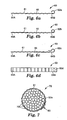
- the invention is a self-mating film as indicated generally in FIG. 3 at 30.
- the configuration of inventive mating film 30 (or “mating film fastener") allows for very low engagement forces, low peel forces (while still preventing flagging), and very high resistance to a shear load when mating film is mated to another portion of itself.
- Mating film 30 includes base sheet 32 having first major surface 34 and second major surface 36.
- a first plurality of ridges 38A extends from first major surface 34 and a second plurality of ridges 38B extends from second major surface 36.
- base sheet 32 is flexible.
- a plurality of ridges 38 extends vertically (i.e., generally perpendicularly) from first and second major surfaces 34 and 36. Ridges 38 are preferably generally parallel to each other. Preferably ridges 38 are between 11 cm (45 mils) to .18 cm (70 mils) high, and base sheet 32 is about .25 cm (10 mils) thick.
- base sheet 32 is formed into a tape-like shape (i.e., having a longer longitudinal dimension, a shorter lateral dimension, and a thickness).
- ridges 38 extend across base sheet 32, along the lateral direction.
- ridges 38 on both first and second major surfaces 34 and 36
- other embodiments are contemplated with ridges 38 extending vertically from only one major surface (e.g. first major surface 34 only).
- ridges 38 may be disposed from each other at constant spacing intervals, irregular spacing intervals are also contemplated.
- the mating film 30 can be used as strips, sheets, or any other shape that can be fabricated from a continuous web.
- a strip of the mating film 30 is wrapped around an object or objects (e.g. a plurality of wires).
- More complex closures, pouches for example, can be made to completely enclose objects (e.g. for protection).
- Other fasteners can be made to secure parallel flat surfaces, like hanging items from a wall.
- Ridges 38 in cross-section are preferably shaped to form substantially identically shaped hooks 40, as illustrated in Fig. 4.
- Each hook 40 includes stem portion 42 and head portion 44.
- Stem portion 42 extends vertically upward from base sheet 32, or in other words generally perpendicular with respect to base sheet.
- Head portion 44 extends generally laterally from stem portion 42, or in other words, in a direction generally parallel to base sheet 32 and towards the most proximate adjacent hooks 40. While an "umbrella" shape hook 40 is illustrated by Fig. 4, it should be understood that other hook configurations are contemplated, such as described in the previously cited patents and publication.
- head portion 44 could extend from only one vertical side 46 of each hook 40.
- head portion 44 could extend from a variety of points along vertical side 46 of hook 40.
- Hooks 40 on mating film 30 are widely spaced (indicated by "S") relative to the width (indicated by "W") of their head portions 44.
- the wide spacing allows hooks from adjacent layers of the mating film to easily mesh, as illustrated in Fig. 4 and wherein a first plurality of meshed hooks from first portion 50 is exemplified by hook 40A and a second plurality of meshed hooks from second portion 52 is exemplified by hook 40B.
- the meshed hooks 40 can then be locked together by shear force to provide a secure closure. This shear force can be provided by applying tension, indicated by arrow "T".
- Tension can be provided by stretching, or simply wrapping mating film 30 around a curve. This tension creates the resulting shear which is created by the tension itself, or elastic recovery of base sheet 32 (elastic recovery is further illustrated with respect to Fig. 5, below). This acts to securely lock first portion 50 of mating film 30 to second portion 52 of mating film 30.
- First and second portions 50 and 52 can be part of one continuous segment of mating film 30 (such as when mating film 30 is wrapped) or be separate non-connected portions of mating film 30, depending upon the end use fastening device application.
- center-to-center spacing of hooks 40 on each major surface relative to their individual head portion 44 widths is greater than that for the fastening film shown in Figures 1 and 2.
- center 47 of stem portion 42 of hook 40C to center 48 of stem portion 42 of hook 40D defines the spacing distance indicated by letter "S".
- hooks 40 of the inventive mating film 30 are widely spaced.
- the spacing to width ratio i.e., S/W
- the spacing to width ratio is higher than about 2 more preferably is higher than about 2.2 and most preferably greater than about 3.
- first and second portions 50 and 52 can be brought together without any hooks 40 touching, much less deforming (as illustrated) greatly minimizing any engagement forces from that necessary in the type of devices operating as described with respect to Fig.'s 1 and 2.
- the two portions 50 and 52 can be lifted apart without any (or minimal) disengagement forces.
- spacing "S" between ridges 3 8 (of hooks 40) can be about the same between adjacent hooks 40, or may be irregular in spacing varying between each pair of adjacent hooks as illustrated in Fig. 4a by S and S'.
- opposing hooks 40 might overlap as the first portion 50 and the second portion 52 of mating film 30 are pressed together. The opposing hooks 40 would then deform and then engage. Similarly, these hooks must deform to disengage normally.
- ridges 38 formed on mating film 30 are spaced at irregular intervals (but at least with as much distance "S" to exceed a S/W ratio of about 2, more preferably exceeding a ratio of about 2.5 and most preferably exceeding a S/W ratio of about 3). By disposing ridges 38 at an irregular interval, the probability is increased that a few hooks 40 will align when first and second portions 50 and 52 are mated so as to deform, while most hooks 40 will not align and will not deform. Thus, while some engagement force will be required, the amount will be minimized, and much less than that required by previous methods.
- the inventive mating film 30 preferably has hooks at least about .11 cm (44 mils) apart with head portions 44 that are .038 cm (15 mils) wide, for a ratio of about 3. This ratio can be increased by stretching the film along its longitudal direction (i.e., in direction "T"), particularly if film is made with an elastomeric polymer.
- Inventive mating films 30 with hook 40 spacing-to-width ratios (S/W) below 2 when the mating film 30 is at rest (i.e., not stretched) can be utilized as well, if the mating film 30 is stretched during wrapping to increase the (S/W) ratio to above 2 during engagement of first portion 50 with second portion 52.
- Mating film 30 can be stretched well beyond the yield of base sheet 32. The spacing between ridges 38 is then greatly increased.
- One embodiment of inventive mating film 30 utilizes spacing to width ratios of over 20. In spite of the large relative spacing between hooks 40, the mating film 30 still wraps securely because there only needs to be a small number of hooks engaged to securely fasten. As long as there is a recoverable force (such as due to elasticity), the strip will engage. Therefore, the inventive mating film 30 may utilize a large range in the spacing-to-width ratio.
- mating film 30 It is desirable for mating film 30 to have a low engagement force, high but appropriate disengagement forces, and good shear performance. There needs to be enough resistance to shear for hook 40 to stay engaged under a load without deformation or failure. More preferably, mating film 30 has no engagement forces, a low disengagement force which is sufficient to prevent flagging (i.e., unfurling or unrolling), and good shear performance, for the desired end use application.
- Inventive mating film 30 engages by shear movement (i.e., longitudinal translation of base sheet 32) in addition to normal movement (i.e., movement perpendicular to base sheet 32 which causes the "meshing" of hooks 40). For example, if first and second portions 50 and 52 of inventive mating film 30 are moved normally such that they are close enough for hooks 40 on first and second portions 50 and 52 to overlap, as illustrated in particular by hooks 40A and 40B in Fig. 4, and there is longitudinal motion of the layers, such as in the direction indicated by "F” of Fig. 5, hooks 40 translate longitudinally towards one another until they engage (as exemplified by hooks 40A and 40B).
- shear movement i.e., longitudinal translation of base sheet 32
- normal movement i.e., movement perpendicular to base sheet 32 which causes the "meshing" of hooks 40.
- the inventive mating films 30 are preferably made from elastomers. Specifically, there needs to be enough elastic recovery to provide shear to engage. While elastic recovery is one method of providing shear force, any method of providing shear force can be used to cause the engagement (or "fastening") of the inventive mating film 3 0.
- One way of providing shear forces between layers of a fastener formed from mating film 30 includes gravity, such as is caused by mounting an object to a wall. Another way is by wrapping the mating film 30 around itself, relying on the tendency of mating film 30 to unwrap. Another way is by wrapping a compressible elastic object, such as a belt or shoe, which urges mating film 30 to unwrap due to the objects tendency to expand.
- first and second portions 50 and 52 are engaged, at least some hooks 40 from first and second portions 50 and 52 are in contact.
- only two hook engagement (specifically exemplified by hooks 40A and 40B) is used, as opposed to the three-hook engagement previously described and illustrated by Fig. 2.
- each hook is engaged by the two opposing adjacent hooks.
- each hook 40 is engaged by a single opposing adjacent hook 40.
- Previous mating films utilizing closely spaced hooks required the hooks to index correctly (i.e., align perfectly one to one) between layers of the film.
- the difference in the radius of curvature between the layers of the film caused mis-indexing of the ridges.
- the outward pointing ridges were spread apart and the inward pointing ridges were compressed. This mis-indexing could increase the force required to force the hooks past one another during engagement and resulted in mismatched ridges that could not be engaged at all.
- the inventive mating film 30 does not need hooks 40 to index match between layers.
- an additional advantage of the present inventive mating film 30 is that the inventive mating film 30 can vary greatly in the stiffness of the material used for hooks 40. This is due to the fact that hooks 40 are not required to deform in order to engage each other. Because mating film 30 is engaged by shear, the mechanical rigidity of hooks 40 is not a large design issue. The hooks 40 only need enough stiffness to function well in shear (so as to resist the applied shear load and required end use application shear loads) as well as preventing flagging). Additionally the inventive mating film may separate by peeling, have peel type of separation, but may also disengage by reverse shear unhooking of ridges 38 so that high rigidity hooks 40 may be used.
- Inventive mating film 30 may be made from a variety of materials but most commonly are made from polymeric materials, using generally any polymer that can be melt processed.
- Thermoset materials, thermoplastic polymers such as homopolymers, copolymers and blends of polymers are useful, and may contain a variety of additives.
- Inorganic materials such as metals may also be used.
- a flexural modulus of from 50 MPa to 1500 MPa for the composition of the mating film 30 including any additives is satisfactory but this may change depending on the application.
- Suitable thermoplastic polymers include, for example, polyolefins such as polypropylene or polyethylene, polystyrene, polycarbonate, polymethyl methacrylate, polyesters preferably polyetheresters, ethylene vinyl acetate copolymers, acrylate-modified ethylene vinyl acetate polymers, ethylene acrylic acid copolymers, nylon, polyvinylchloride, and engineering polymers such as polyketones or polymethylpentanes.
- Elastomers include, for example, natural or synthetic rubber, styrene block copolymers containing isoprene, butadiene, or ethylene (butylene) blocks, metallocene-catalyzed polyolefins, polyurethanes, and polydiorganosiloxanes. Mixtures of the polymers and/or elastomers may also be used.
- Suitable additives include, for example, plasticizers, tackifiers, fillers, colorants, ultraviolet light stabilizers, antioxidants, processing aids (urethanes, silicones, fluoropolymers, etc.), low-coefficient-of-friction materials (silicones), conductive fillers to give the fastener a level of conductivity, pigments, and combinations thereof.
- additives can be present in amounts up to 50 percent by weight of the composition depending on the application.
- Mating films 30 of the invention can be formed in a manner known in the art, such as by extruding a polymeric web through a die (not shown) having an opening cut, for example, by electrical discharge machining.
- the shape of the die is designed to generate a web (not shown) with a desired cross-sectional shape or profile.
- the web is generally quenched after leaving the die by pulling it through a quenching material such as water.
- a wetting agent may be required in the quenching medium to assure good wetting of the whole surface of the extruded web, including spaces between ridges.
- fasteners of the invention can be prepared in other ways, for example, by injection molding or casting.
- ridged fastener structure of the invention can be incorporated into a larger article having other functions besides fastening.
- a frame could be mounted on a wall to support a picture or other display using the inventive mating film 30.
- the fastener structure can be incorporated into the larger article in various ways, e.g., by inserting an already prepared fastener into a mold and molding the rest of the article around the fastener; or by configuring a mold surface with mold structure shaped to form a fastener structure of the invention.
- the term "base sheet" herein includes the structure of the article into which the fastener structure is incorporated.
- mating film 30 may include multiple layers, generally of different composition. Such multiple layers can be provided by coextrusion techniques (as described, for example, in U.S. Patent 6,106,922, published April 15, 1999), which may involve passing different melt streams from different extruders into a multiple-manifold die or a multiple-layer feed block and a film die (not shown). The individual streams merge in the feed block and enter the die as a layered stack that flows out into layered sheets as the material leaves the die. The die is patterned to form the ridged configuration of the mating film 30. Mating film 30 of the invention thus may have base sheet 32 of one composition and ridges 38 of a different composition.
- one portion of ridges 38 may have a different composition from other portions of the same ridge 38.
- the portion of the ridge 38 furthest from base sheet 32 may include a composition that forms a lower-friction surface than the rest of ridge 38.
- Mating film fasteners 30 embodied in the present invention have a number of important advantages, which adapt the mating film fasteners 30 to a number of important uses. For example, because the mating film 30 is self-mating, inventory requirements and related costs are reduced. This is due to the fact that the manufacturing process is simplified (i.e., only one web is used, and no lamination is required). In addition, one longitudinal piece of a single mating film 30 can be used as a complete closure device, as when the mating film fastener takes the form of a tape or strap wrapped around a bundle of items (discussed further with respect to Fig. 7).
- Base sheet 32 of mating film 30 should have adequate tensile strength to resist tensions during use. This tensile strength may be provided by choice of composition of base sheet 32, manufacture of mating film 30 as a coextruded product with a material for base sheet 32 specially adapted for use as a tensile strap, or addition of a sheet or layer to base sheet 32.
- Mating film 30 may be twisted and wrapped to allow the ridges 38 surfaces from one surface (e.g. first major surface 34) at the respective ends of the strap to interengage.
- ridges 38 may be provided on both sides of the base sheet 32 (i.e., both first major surface 34 and second major surface 36). Opposite longitudinal ends of mating film 30 may have ridges 38 on opposite surfaces of mating film 30 strap, with the result that ridges 38 may be inter-engaged without twisting the strap.
- mating film 60 having base film 65 and ridges 61 can be combined with integrated clips 62a-62d, as shown in Fig.'s 6a-6d.
- Mating films 60 can be used to bundle to all sorts of items, including electrical wires, tubes, hoses or any other item that may require binding or girding.
- mating film 60 illustrated in Fig.'s 6a - 7 includes ridges as described previously with respect to Fig.'s 3-5. The scale of Fig.'s 6a - 7, however, is such that hooks 40 formed ridges 38 are not illustrated.
- each integrated clip 62a-62d can be a variety of configurations depending upon the end use fastening application.
- integrated clip 62a is a simple "C” shaped curved configuration.
- Integrated clip 62b is formed in the shape of a coil. The particular advantage of a coil configuration is the expandability of the coil to fit various object diameters.
- Integrated clip 62c is formed in a "bobby pin” shaped configuration, while integrated clip 62d is disposed in the longitudinal and lateral plane forming base sheet 32.
- Integrated clips 62 can be formed on one or both longitudinal ends 64a and 64b of mating film 60 in several ways, depending on the rigidity and formability of the polymer from which the mating film 60 was made.
- integrated clip 62 can be fashioned by thermoforming a sheet of polyester into integrated clip 62 and attaching integrated clip 62 to one longitudal end 64b of base sheet 65 of mating film 60.
- the connection of integrated clip 62 is preferably permanent, but could be made removable.
- clip can be formed from the profile-extruded web itself, or can be glued or welded to the web.
- Integrated clip 62a can be used to secure mating film 60 to one strand 70 in bundle 72 as illustrated in Fig. 7. Such a configuration holds mating film 60 in place when mating film 60 is wrapped around the bundle.
- mating film 60 also known as a "bundling strap”
- Integrated clip 62 is simply pulled over one or more strand(s) in bundle72 and the mating film 30 is wrapped and then secured in place.
- mating film 30 allows tight bundling of strands 70, which allows for ease in providing shear forces.
- mating film 30 can be wrapped directly around bundle 72 without requiring the operator to place his fingers on mating film 30 to hold it in place as mating film 30 is wrapped.
- integrated clips are illustrated for use with inventive mating film as described in Fig's 1-5, other types of film and mating devices such as those described in the background (e.g. hook and loop) may also utilize a clip attached to a longitudinal end in order to secure the fastener in place as it is being wrapped or otherwise secured.
- stretch locking mating films described in the following examples were profile extruded on a pilot line.
- Many samples of stretch locking mating film were made from thermoplastic elastomers such as Engage®, Dupont Dow Elastomers L.L.C., Wilmington, DE, Hytrel®, DuPont Engineering Polymers, Wilmington, DE, and Santoprene®, Advanced Elastomer Systems, L.P., Akron, OH.
- other samples were made from polyethylene and polyethylene/polypropylene copolymers.
- the main components of the pilot line are a single screw extruder, a die, a die lip, a quench tank, and a take-up winder all of which are common components known to one skilled in the art.
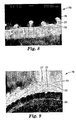
- An 8-inch wide flexible lip film die was a modified to accept a dual-sided profile die lip. Film was extruded through the die lip in the direction that is perpendicular to the plane of the picture shown in Fig.'s 8 and 9.
- the modifications to the die included an insert to allow for the tall features of the dual-sided die lip and holes tapped into the flexible lip to secure the upper part of the die lip.
- the die lip was bolted onto both the base of the die (the lower half) and lip of the die (the upper half).
- Mating film 76 is shown in Figures 8 and 9. This mating film 76 was made of Hytrel® 4056, DuPont Engineering Polymers, Wilmington, DE, a thermoplastic polyester elastomer. Fig. 8 shows a cross-sectional profile of mating film 76, Fig. 9 shows film 76 wrapped around screw head 80 with interlocked hooks 77.
- Mating film 76 has approximately a .11 cm (44 mils) hook 77 spacing and approximately a .041 cm (16 mil) hook head portion 78 width, for a ratio of about 2.8.
- mating film 76 is constructed so that the applied load during use of mating film 76 is perpendicular to ridge 79 orientation. Ridges 79 are oriented normal to the plane of Fig. 8.
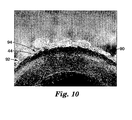
- Mating film 90 as illustrated in Fig. 10, made according to the present invention was stretched well beyond its yield strain and then tightly wrapped around the head of a screw.
- ridges 92 of hooks 94 were distorted and became curved and wavy.
- the waviness did not prevent mating film 90 from interlocking.
- the strip of mating film 90 used in Example 2 was cut from the same web as the strip shown in Fig. 8 and in Fig. 9. However, after being stretched, hooks 94 were about .51 cm (200 mils) apart. The width of each head portion 44 was .041 cm (16 mils), resulting in a spacing-to-width ratio of 13.
- objects can be securely wrapped with mating films that have high hook spacing to width ratios and some deformation of the hook ridges.
Claims (19)
- Film s'accrochant spontanément (30, 60), comprenant :une feuille de base (32) comportant une première surface principale (34) ;une première pluralité de nervures généralement parallèles (38) qui s'avancent en saillie à partir de la première surface principale (34), chacune de la pluralité de premières nervures (38) comprenant une première partie constituée d'une tige (42) fixée à, et généralement verticale sur, la feuille de base (32) et une première partie constituée d'une tête (44) écartée de la première surface principale (34), qui s'étend généralement latéralement à partir de la partie constituée d'une tige (42) de façon à définir une première distance latérale ; etcaractérisé en ce que le centre de chaque partie constituée d'une tige d'une nervure (42) est séparé du centre de chaque partie constituée d'une tige d'une nervure adjacente (42) par une distance supérieure à environ 2 fois la distance latérale définie par la partie constituée d'une tête (44).
- Film s'accrochant spontanément selon la revendication 1, dans lequel les nervures (38) s'étendent transversalement à travers la feuille de base (32).
- Film s'accrochant spontanément selon la revendication 1, dans lequel l'une au moins de la feuille de base (32) et des nervures (38) se compose au moins en partie d'un polymère élastomère.
- Film s'accrochant spontanément selon la revendication 1, dans lequel les feuilles de base (32) et les nervures (38) sont co-extrudées à partir de différents polymères.
- Film s'accrochant spontanément selon la revendication 1, comprenant en outre :une deuxième surface principale (36) sur la feuille de base (32), etune pluralité de nervures généralement parallèles (38) qui s'avancent en saillie à partir de la deuxième surface principale (36).
- Film s'accrochant spontanément selon la revendication 1, et comprenant en outre :une attache (62, 62a-62d) disposée à une extrémité longitudinale de la feuille de base (60).
- Film s'accrochant spontanément selon la revendication 6, dans lequel l'attache (62) se compose d'un matériau différent de celui de la feuille de base (60).
- Film s'accrochant spontanément selon la revendication 6, dans lequel l'attache (62a) est formée pour former un "C".
- Film s'accrochant spontanément selon la revendication 6, dans lequel l'attache (62) est formée en un seul bloc avec la feuille de base.
- Film s'accrochant spontanément selon la revendication 1, dans lequel le centre de chaque partie constituée d'une tige d'une nervure (42) est séparé du centre de chaque partie constituée d'une tige d'une nervure adjacente (42) par une distance supérieure à environ 2,5 fois la distance latérale définie par la partie constituée d'une tête (44).
- Film s'accrochant spontanément selon la revendication 1, dans lequel le centre de chaque partie constituée d'une tige d'une nervure (42) est séparé du centre de chaque partie constituée d'une tige d'une nervure adjacente (42) par une distance supérieure à environ 3 fois la distance latérale définie par la partie constituée d'une tête (44).
- Film s'accrochant spontanément selon la revendication 1, dans lequel l'écartement varie entre chaque partie constituée d'une tige d'une nervure adjacente (42).
- Film s'accrochant spontanément selon la revendication 1, dans lequel l'écartement est fondamentalement constant entre chaque partie constituée d'une tige d'une nervure adjacente (42).
- Film s'accrochant spontanément selon la revendication 1, dans lequel chaque crochet adjacent (40) a une forme fondamentalement verticale.
- Méthode de fixation, comprenant :la disposition d'une première partie (50) d'une feuille de base (32) comportant une première surface principale (34) et une première pluralité de nervures en forme de crochets (38) qui s'avancent en saillie à partir de la première surface principale (34) à proximité d'une deuxième partie (52) de la feuille de base (32) comportant une deuxième pluralité de nervures (38) qui s'avancent en saillie à partir de la deuxième partie ;un déplacement en translation de la première partie de la feuille de base (32) perpendiculairement vers la deuxième partie de la feuille de base (32) ;la superposition des nervures en forme de crochets (38) de la première partie (50) et des nervures en forme de crochets (38) de la deuxième partie (52) ;un déplacement en translation de la première partie, longitudinalement par rapport à la deuxième partie ; etl'engagement de chaque nervure d'une partie de la pluralité de nervures (38) de la première partie de la feuille de base (32) dans l'une seulement de la pluralité de nervures (38) de la deuxième partie,caractérisée en ce que
le centre de chaque première nervure (38) est séparé du centre de chaque première nervure adjacente (38) par une distance supérieure à environ 2 fois la distance latérale définie par la première partie constituée d'une tête, et en ce que le centre de chaque deuxième nervure (38) est séparé du centre de chaque deuxième nervure adjacente (38) par une distance supérieure à environ 2 fois la distance latérale définie par la deuxième partie constituée d'une tête. - Méthode selon la revendication 15, et comprenant en outre :l'utilisation d'une distance d'écartement constante entre la première pluralité de nervures (38).
- Méthode selon la revendication 15, et comprenant en outre :l'utilisation de distances d'écartement irrégulières entre la première pluralité de nervures (38).
- Méthode selon la revendication 15, et comprenant en outre :la déformation élastique de la feuille de base (32) pour produire un déplacement en translation longitudinal entre la première partie et la deuxième partie.
- Film s'accrochant spontanément selon la revendication 1, dans lequel :la feuille de base (32) comporte en outre une deuxième surface principale (36), le film comprenant en outre :dans lequel le centre de chaque première nervure (38) est séparé du centre de chaque première nervure adjacente (38) par une distance supérieure à environ 2,5 fois la première distance latérale définie par la première partie constituée d'une tête (44),une deuxième pluralité de nervures généralement parallèles (38) qui s'étendent à partir de la deuxième surface principale (36), la deuxième pluralité de nervures (38) comprenant une deuxième partie constituée d'une tige (42) fixée à, et généralement verticale sur, la feuille de base (32), et une deuxième partie constituée d'une tête (44) qui s'étend généralement latéralement à partir de la deuxième partie constituée d'une tige (32) de façon à définir une deuxième distance latérale ;
dans lequel le centre de chaque deuxième nervure (38B) est séparé du centre de chaque deuxième nervure adjacente (38B) par une distance supérieure à environ 2,5 fois la deuxième distance latérale définie par la deuxième partie constituée d'une tête (44) ; et
une attache (62) disposée à une extrémité longitudinale de la feuille de base.
Applications Claiming Priority (5)
| Application Number | Priority Date | Filing Date | Title |
|---|---|---|---|
| US32315001P | 2001-09-18 | 2001-09-18 | |
| US323150P | 2001-09-18 | ||
| US10/150,478 US6763556B2 (en) | 2001-09-18 | 2002-05-17 | Mating film and method for bundling and wrapping |
| US150478 | 2002-05-17 | ||
| PCT/US2002/027335 WO2003024265A1 (fr) | 2001-09-18 | 2002-08-27 | Film s'accrochant spontanement et procede d'empaquetage et d'emballage |
Publications (2)
| Publication Number | Publication Date |
|---|---|
| EP1427306A1 EP1427306A1 (fr) | 2004-06-16 |
| EP1427306B1 true EP1427306B1 (fr) | 2007-04-25 |
Family
ID=26847712
Family Applications (1)
| Application Number | Title | Priority Date | Filing Date |
|---|---|---|---|
| EP02757419A Expired - Lifetime EP1427306B1 (fr) | 2001-09-18 | 2002-08-27 | Film s'accrochant spontanement et procede d'empaquetage et d'emballage |
Country Status (6)
| Country | Link |
|---|---|
| US (1) | US6763556B2 (fr) |
| EP (1) | EP1427306B1 (fr) |
| JP (1) | JP2005502411A (fr) |
| AT (1) | ATE360382T1 (fr) |
| DE (1) | DE60219805T2 (fr) |
| WO (1) | WO2003024265A1 (fr) |
Families Citing this family (27)
| Publication number | Priority date | Publication date | Assignee | Title |
|---|---|---|---|---|
| JP3939155B2 (ja) * | 2002-01-17 | 2007-07-04 | スリーエム イノベイティブ プロパティズ カンパニー | 埋込取付式ファスナー |
| US20060159372A1 (en) * | 2005-01-14 | 2006-07-20 | Illinois Tool Works Inc. | Zipper for transverse direction front panel pouch |
| FR2917275A1 (fr) * | 2007-06-13 | 2008-12-19 | Aplix Sa | Dispositif auto-agrippant a crochets a grande souplesse |
| US8096520B2 (en) * | 2008-06-04 | 2012-01-17 | Sohn Cheryl L | Connector system |
| EP2175527A1 (fr) * | 2008-10-09 | 2010-04-14 | 3M Innovative Properties Company | Composant de fixation mécanique refermable |
| US9551439B2 (en) * | 2009-03-30 | 2017-01-24 | 3M Innovative Properties Company | Wire management article |
| US9119444B2 (en) * | 2009-05-01 | 2015-09-01 | Chittaranjan Narandas Nirmel | Versatile hook-and-loop fastener system |
| EP3261100A1 (fr) | 2009-06-19 | 2017-12-27 | 3M Innovative Properties Company | Câble électrique blindé et son procédé de fabrication |
| US9685259B2 (en) | 2009-06-19 | 2017-06-20 | 3M Innovative Properties Company | Shielded electrical cable |
| CN102884592B (zh) | 2010-08-31 | 2017-12-26 | 3M创新有限公司 | 具有电介质间距的屏蔽电缆 |
| SG187819A1 (en) | 2010-08-31 | 2013-03-28 | 3M Innovative Properties Co | Shielded electrical cable |
| EP3200198A1 (fr) | 2010-08-31 | 2017-08-02 | 3M Innovative Properties Company | Câble électrique blindé en configuration twinaxiale |
| US10147522B2 (en) | 2010-08-31 | 2018-12-04 | 3M Innovative Properties Company | Electrical characteristics of shielded electrical cables |
| BR112013003294A2 (pt) | 2010-08-31 | 2016-06-14 | 3M Innovative Properties Co | "cabo elétrico blindado e cabo em fita elétrico blindado" |
| EP3573077A1 (fr) | 2010-08-31 | 2019-11-27 | 3M Innovative Properties Company | Câble électrique blindé à haute densité et autres câbles blindés, systèmes et procédés |
| WO2012039736A1 (fr) | 2010-09-23 | 2012-03-29 | 3M Innovative Properties Company | Câble électrique blindé |
| US8875356B2 (en) | 2011-10-06 | 2014-11-04 | Intercontinental Great Brands Llc | Mechanical and adhesive based reclosable fasteners |
| US9015910B2 (en) * | 2012-02-09 | 2015-04-28 | Illinois Tool Works Inc. | Spaced multi-rib zipper |
| US9615614B2 (en) | 2012-10-16 | 2017-04-11 | Velcro BVBA | Fastening pouch or pocket flaps |
| US9655413B2 (en) | 2013-03-15 | 2017-05-23 | Thomas M. Adams | Self adhering connection surfaces, straps, snaps and bands |
| US9198483B2 (en) | 2013-03-15 | 2015-12-01 | Thomas M. Adams | Self adhering connection surfaces, straps, snaps and bands |
| FR3027775B1 (fr) * | 2014-10-31 | 2016-11-11 | Aplix Sa | Dispositif de fermeture a crochets dans crochets a effet sensoriel |
| GB2533980B (en) * | 2015-03-19 | 2017-04-12 | D R Baling Wire Mft Ltd | Improved baling strap |
| US10576391B1 (en) * | 2019-02-07 | 2020-03-03 | Kun Yuan Tong | Building piece comprising two rigid interlockable wings and a flexible belt therebetween |
| US20220175094A1 (en) * | 2019-04-10 | 2022-06-09 | 3M Innovative Properties Company | Self-mating mechanical fastener with conductive contact element |
| WO2021116864A1 (fr) * | 2019-12-09 | 2021-06-17 | 3M Innovative Properties Company | Article polymère coextrudé et son procédé de fabrication |
| US20230020435A1 (en) * | 2021-07-13 | 2023-01-19 | Six Foot Plus Systems, LLC | Wire, conduit, and electronics organizer |
Family Cites Families (34)
| Publication number | Priority date | Publication date | Assignee | Title |
|---|---|---|---|---|
| NL79380C (fr) | 1951-10-22 | 1900-01-01 | ||
| GB760697A (en) | 1953-09-02 | 1956-11-07 | Dagmar O Connor | Improvements in fasteners for overlapping elements |
| US3009235A (en) | 1957-10-02 | 1961-11-21 | Internat Velcro Company | Separable fastening device |
| US3266113A (en) | 1963-10-07 | 1966-08-16 | Minnesota Mining & Mfg | Interreacting articles |
| US3557413A (en) | 1968-09-23 | 1971-01-26 | William H Engle | Nonmechanical closure |
| US3592428A (en) * | 1968-11-04 | 1971-07-13 | Le Roy F Mcfarlane | Cable clamps |
| US3586220A (en) | 1968-12-18 | 1971-06-22 | Cobbs Mfg Co | Strip fastener for holders |
| US3682163A (en) * | 1970-09-18 | 1972-08-08 | Walter A Plummer | Snap-on orthopedic splint |
| US4046408A (en) * | 1973-08-03 | 1977-09-06 | Steven Ausnit | Omni-directional fastener |
| US4290174A (en) | 1976-08-13 | 1981-09-22 | Minnesota Mining And Manufacturing Company | Separable fastener and article for making same |
| US4894060A (en) | 1988-01-11 | 1990-01-16 | Minnesota Mining And Manufacturing Company | Disposable diaper with improved hook fastener portion |
| FR2641584B1 (fr) | 1988-01-18 | 1991-05-10 | Caoutchouc Manuf Plastique | Perfectionnement a un dispositif de jonctionnement de panneaux ou de realisation de conduits |
| FR2636683B2 (fr) | 1988-02-26 | 1990-12-28 | Berger Michel | Systeme d'assemblage par accrochage comportant des elements d'accrochage formes par des nervures curvilignes pourvues de levres elastiquement deformables |
| US5269776A (en) * | 1989-03-24 | 1993-12-14 | Paragon Trade Brands, Inc. | Disposable diaper with refastenable mechanical fastening system |
| US5179767A (en) * | 1990-07-16 | 1993-01-19 | Allan Robert M | Connector apparatus |
| JPH04109904A (ja) * | 1990-08-31 | 1992-04-10 | Kuraray Co Ltd | モールド成形用面ファスナー部材 |
| US5235731A (en) | 1992-03-26 | 1993-08-17 | Kuraray Co., Ltd. | Molded-resin separable fastener and fastening system utilizing the same |
| JPH0739407A (ja) * | 1993-07-28 | 1995-02-10 | Minnesota Mining & Mfg Co <3M> | 対面係合ファスナー部材とそのファスナー部材を備えたファスナー |
| JPH0779810A (ja) * | 1993-08-25 | 1995-03-28 | Minnesota Mining & Mfg Co <3M> | 対面係合ファスナー部材とその製造方法 |
| US5396687A (en) * | 1993-11-12 | 1995-03-14 | Osterman; Eric F. | Mechanical fastener |
| SI0746504T1 (en) | 1994-03-03 | 1999-12-31 | Wolfgang Fr�hlich | Web-shaped member and connection device between two web-shaped members |
| US5713111A (en) * | 1994-07-27 | 1998-02-03 | Minnesota Mining And Manufacturing Company | Method for making an interengaging fastener having reduced engagement force |
| US5500268A (en) * | 1995-01-31 | 1996-03-19 | Aplix, Inc. | Fastener assembly with magnetic side and end seals and method |
| JPH09315A (ja) * | 1995-06-20 | 1997-01-07 | Ykk Kk | 成形面ファスナー及びその製造方法 |
| JPH09238714A (ja) * | 1996-03-04 | 1997-09-16 | Ykk Corp | 合成樹脂製の一体成形面ファスナー |
| US5953797A (en) * | 1996-10-09 | 1999-09-21 | Velcro Industries B.V. | Hook fasteners and methods of manufacture |
| JPH10201504A (ja) * | 1997-01-20 | 1998-08-04 | Ykk Corp | 一体成形により得られる面ファスナー用係合部材 |
| US5867876A (en) * | 1997-05-12 | 1999-02-09 | Petersen; Edward C. | Male-to-male connector apparatus having symmetrical and uniform connector matrix |
| JP3028212B2 (ja) | 1997-05-27 | 2000-04-04 | モリト株式会社 | 結束具 |
| US6106922A (en) | 1997-10-03 | 2000-08-22 | 3M Innovative Company | Coextruded mechanical fastener constructions |
| US6460230B2 (en) * | 2000-01-12 | 2002-10-08 | Kuraray Co., Ltd. | Mold-in fastening member and production of molded resin article having mold-in fastening member |
| US6367128B1 (en) | 2000-02-10 | 2002-04-09 | 3M Innovative Properties Company | Self-mating reclosable mechanical fastener |
| ATE340744T1 (de) | 2000-02-10 | 2006-10-15 | 3M Innovative Properties Co | Wiederverschliessbarer bündelungsriemen mit klettverschluss |
| US6588074B2 (en) | 2000-02-10 | 2003-07-08 | 3M Innovative Properties Company | Self-mating reclosable binding strap and fastener |
-
2002
- 2002-05-17 US US10/150,478 patent/US6763556B2/en not_active Expired - Lifetime
- 2002-08-27 EP EP02757419A patent/EP1427306B1/fr not_active Expired - Lifetime
- 2002-08-27 JP JP2003528168A patent/JP2005502411A/ja active Pending
- 2002-08-27 AT AT02757419T patent/ATE360382T1/de not_active IP Right Cessation
- 2002-08-27 DE DE60219805T patent/DE60219805T2/de not_active Expired - Fee Related
- 2002-08-27 WO PCT/US2002/027335 patent/WO2003024265A1/fr active IP Right Grant
Also Published As
| Publication number | Publication date |
|---|---|
| DE60219805D1 (de) | 2007-06-06 |
| ATE360382T1 (de) | 2007-05-15 |
| US20030051320A1 (en) | 2003-03-20 |
| EP1427306A1 (fr) | 2004-06-16 |
| JP2005502411A (ja) | 2005-01-27 |
| US6763556B2 (en) | 2004-07-20 |
| DE60219805T2 (de) | 2008-01-17 |
| WO2003024265A1 (fr) | 2003-03-27 |
Similar Documents
| Publication | Publication Date | Title |
|---|---|---|
| EP1427306B1 (fr) | Film s'accrochant spontanement et procede d'empaquetage et d'emballage | |
| US6546604B2 (en) | Self-mating reclosable mechanical fastener and binding strap | |
| US6367128B1 (en) | Self-mating reclosable mechanical fastener | |
| EP1253836B1 (fr) | Fixation et bande de fermeture mecanique s'accrochant spontanement | |
| US11058186B2 (en) | Dimensionally flexible touch fastener strip | |
| US5932311A (en) | Method of making and using a touch fastener with magnetic attractant | |
| US6540863B2 (en) | Forming fastener components of multiple streams of resin | |
| EP1372424A2 (fr) | Bandes de fixation a boucles et a crochets legeres, flexibles et tres resistantes | |
| US20090282654A1 (en) | Fastener Products and Related Methods | |
| US7140774B2 (en) | Slidable fastener bearing assembly | |
| US20030084553A1 (en) | Hook engageable loops | |
| EP1609383A1 (fr) | Dispositif d'attache coulissante préassemblé et méthode de montage | |
| CA2212312C (fr) | Attache par contact avec partie d'attraction magnetique | |
| JPH06296509A (ja) | 面ファースナーとその製造法 |
Legal Events
| Date | Code | Title | Description |
|---|---|---|---|
| PUAI | Public reference made under article 153(3) epc to a published international application that has entered the european phase |
Free format text: ORIGINAL CODE: 0009012 |
|
| 17P | Request for examination filed |
Effective date: 20040330 |
|
| AK | Designated contracting states |
Kind code of ref document: A1 Designated state(s): AT BE BG CH CY CZ DE DK EE ES FI FR GB GR IE IT LI LU MC NL PT SE SK TR |
|
| AX | Request for extension of the european patent |
Extension state: AL LT LV MK RO SI |
|
| GRAP | Despatch of communication of intention to grant a patent |
Free format text: ORIGINAL CODE: EPIDOSNIGR1 |
|
| GRAS | Grant fee paid |
Free format text: ORIGINAL CODE: EPIDOSNIGR3 |
|
| GRAA | (expected) grant |
Free format text: ORIGINAL CODE: 0009210 |
|
| AK | Designated contracting states |
Kind code of ref document: B1 Designated state(s): AT BE BG CH CY CZ DE DK EE ES FI FR GB GR IE IT LI LU MC NL PT SE SK TR |
|
| PG25 | Lapsed in a contracting state [announced via postgrant information from national office to epo] |
Ref country code: CH Free format text: LAPSE BECAUSE OF FAILURE TO SUBMIT A TRANSLATION OF THE DESCRIPTION OR TO PAY THE FEE WITHIN THE PRESCRIBED TIME-LIMIT Effective date: 20070425 Ref country code: FI Free format text: LAPSE BECAUSE OF FAILURE TO SUBMIT A TRANSLATION OF THE DESCRIPTION OR TO PAY THE FEE WITHIN THE PRESCRIBED TIME-LIMIT Effective date: 20070425 Ref country code: LI Free format text: LAPSE BECAUSE OF FAILURE TO SUBMIT A TRANSLATION OF THE DESCRIPTION OR TO PAY THE FEE WITHIN THE PRESCRIBED TIME-LIMIT Effective date: 20070425 |
|
| REG | Reference to a national code |
Ref country code: GB Ref legal event code: FG4D |
|
| REG | Reference to a national code |
Ref country code: IE Ref legal event code: FG4D |
|
| REG | Reference to a national code |
Ref country code: CH Ref legal event code: EP |
|
| REF | Corresponds to: |
Ref document number: 60219805 Country of ref document: DE Date of ref document: 20070606 Kind code of ref document: P |
|
| PG25 | Lapsed in a contracting state [announced via postgrant information from national office to epo] |
Ref country code: SE Free format text: LAPSE BECAUSE OF FAILURE TO SUBMIT A TRANSLATION OF THE DESCRIPTION OR TO PAY THE FEE WITHIN THE PRESCRIBED TIME-LIMIT Effective date: 20070725 |
|
| PG25 | Lapsed in a contracting state [announced via postgrant information from national office to epo] |
Ref country code: ES Free format text: LAPSE BECAUSE OF FAILURE TO SUBMIT A TRANSLATION OF THE DESCRIPTION OR TO PAY THE FEE WITHIN THE PRESCRIBED TIME-LIMIT Effective date: 20070805 |
|
| PG25 | Lapsed in a contracting state [announced via postgrant information from national office to epo] |
Ref country code: PT Free format text: LAPSE BECAUSE OF FAILURE TO SUBMIT A TRANSLATION OF THE DESCRIPTION OR TO PAY THE FEE WITHIN THE PRESCRIBED TIME-LIMIT Effective date: 20070925 |
|
| ET | Fr: translation filed | ||
| REG | Reference to a national code |
Ref country code: CH Ref legal event code: PL |
|
| NLV1 | Nl: lapsed or annulled due to failure to fulfill the requirements of art. 29p and 29m of the patents act | ||
| PG25 | Lapsed in a contracting state [announced via postgrant information from national office to epo] |
Ref country code: AT Free format text: LAPSE BECAUSE OF FAILURE TO SUBMIT A TRANSLATION OF THE DESCRIPTION OR TO PAY THE FEE WITHIN THE PRESCRIBED TIME-LIMIT Effective date: 20070425 |
|
| PG25 | Lapsed in a contracting state [announced via postgrant information from national office to epo] |
Ref country code: BE Free format text: LAPSE BECAUSE OF FAILURE TO SUBMIT A TRANSLATION OF THE DESCRIPTION OR TO PAY THE FEE WITHIN THE PRESCRIBED TIME-LIMIT Effective date: 20070425 |
|
| PG25 | Lapsed in a contracting state [announced via postgrant information from national office to epo] |
Ref country code: DK Free format text: LAPSE BECAUSE OF FAILURE TO SUBMIT A TRANSLATION OF THE DESCRIPTION OR TO PAY THE FEE WITHIN THE PRESCRIBED TIME-LIMIT Effective date: 20070425 Ref country code: CZ Free format text: LAPSE BECAUSE OF FAILURE TO SUBMIT A TRANSLATION OF THE DESCRIPTION OR TO PAY THE FEE WITHIN THE PRESCRIBED TIME-LIMIT Effective date: 20070425 Ref country code: NL Free format text: LAPSE BECAUSE OF FAILURE TO SUBMIT A TRANSLATION OF THE DESCRIPTION OR TO PAY THE FEE WITHIN THE PRESCRIBED TIME-LIMIT Effective date: 20070425 Ref country code: BG Free format text: LAPSE BECAUSE OF FAILURE TO SUBMIT A TRANSLATION OF THE DESCRIPTION OR TO PAY THE FEE WITHIN THE PRESCRIBED TIME-LIMIT Effective date: 20070725 |
|
| PG25 | Lapsed in a contracting state [announced via postgrant information from national office to epo] |
Ref country code: SK Free format text: LAPSE BECAUSE OF FAILURE TO SUBMIT A TRANSLATION OF THE DESCRIPTION OR TO PAY THE FEE WITHIN THE PRESCRIBED TIME-LIMIT Effective date: 20070425 |
|
| PLBE | No opposition filed within time limit |
Free format text: ORIGINAL CODE: 0009261 |
|
| STAA | Information on the status of an ep patent application or granted ep patent |
Free format text: STATUS: NO OPPOSITION FILED WITHIN TIME LIMIT |
|
| 26N | No opposition filed |
Effective date: 20080128 |
|
| PG25 | Lapsed in a contracting state [announced via postgrant information from national office to epo] |
Ref country code: MC Free format text: LAPSE BECAUSE OF NON-PAYMENT OF DUE FEES Effective date: 20070831 Ref country code: GR Free format text: LAPSE BECAUSE OF FAILURE TO SUBMIT A TRANSLATION OF THE DESCRIPTION OR TO PAY THE FEE WITHIN THE PRESCRIBED TIME-LIMIT Effective date: 20070726 |
|
| PG25 | Lapsed in a contracting state [announced via postgrant information from national office to epo] |
Ref country code: IE Free format text: LAPSE BECAUSE OF NON-PAYMENT OF DUE FEES Effective date: 20070827 |
|
| PGFP | Annual fee paid to national office [announced via postgrant information from national office to epo] |
Ref country code: FR Payment date: 20080818 Year of fee payment: 7 Ref country code: IT Payment date: 20080825 Year of fee payment: 7 |
|
| PGFP | Annual fee paid to national office [announced via postgrant information from national office to epo] |
Ref country code: GB Payment date: 20080827 Year of fee payment: 7 |
|
| PG25 | Lapsed in a contracting state [announced via postgrant information from national office to epo] |
Ref country code: EE Free format text: LAPSE BECAUSE OF FAILURE TO SUBMIT A TRANSLATION OF THE DESCRIPTION OR TO PAY THE FEE WITHIN THE PRESCRIBED TIME-LIMIT Effective date: 20070425 |
|
| PGFP | Annual fee paid to national office [announced via postgrant information from national office to epo] |
Ref country code: DE Payment date: 20080930 Year of fee payment: 7 |
|
| PG25 | Lapsed in a contracting state [announced via postgrant information from national office to epo] |
Ref country code: CY Free format text: LAPSE BECAUSE OF FAILURE TO SUBMIT A TRANSLATION OF THE DESCRIPTION OR TO PAY THE FEE WITHIN THE PRESCRIBED TIME-LIMIT Effective date: 20070425 |
|
| PG25 | Lapsed in a contracting state [announced via postgrant information from national office to epo] |
Ref country code: LU Free format text: LAPSE BECAUSE OF NON-PAYMENT OF DUE FEES Effective date: 20070827 |
|
| PG25 | Lapsed in a contracting state [announced via postgrant information from national office to epo] |
Ref country code: TR Free format text: LAPSE BECAUSE OF FAILURE TO SUBMIT A TRANSLATION OF THE DESCRIPTION OR TO PAY THE FEE WITHIN THE PRESCRIBED TIME-LIMIT Effective date: 20070425 |
|
| GBPC | Gb: european patent ceased through non-payment of renewal fee |
Effective date: 20090827 |
|
| REG | Reference to a national code |
Ref country code: FR Ref legal event code: ST Effective date: 20100430 |
|
| PG25 | Lapsed in a contracting state [announced via postgrant information from national office to epo] |
Ref country code: FR Free format text: LAPSE BECAUSE OF NON-PAYMENT OF DUE FEES Effective date: 20090831 Ref country code: DE Free format text: LAPSE BECAUSE OF NON-PAYMENT OF DUE FEES Effective date: 20100302 |
|
| PG25 | Lapsed in a contracting state [announced via postgrant information from national office to epo] |
Ref country code: GB Free format text: LAPSE BECAUSE OF NON-PAYMENT OF DUE FEES Effective date: 20090827 |
|
| PG25 | Lapsed in a contracting state [announced via postgrant information from national office to epo] |
Ref country code: IT Free format text: LAPSE BECAUSE OF NON-PAYMENT OF DUE FEES Effective date: 20090827 |