EP1426295A1 - Verfahren und Vorrichtung zum Versiegeln von Behältern mit einem bahnförmigen Material - Google Patents
Verfahren und Vorrichtung zum Versiegeln von Behältern mit einem bahnförmigen Material Download PDFInfo
- Publication number
- EP1426295A1 EP1426295A1 EP03027232A EP03027232A EP1426295A1 EP 1426295 A1 EP1426295 A1 EP 1426295A1 EP 03027232 A EP03027232 A EP 03027232A EP 03027232 A EP03027232 A EP 03027232A EP 1426295 A1 EP1426295 A1 EP 1426295A1
- Authority
- EP
- European Patent Office
- Prior art keywords
- container
- blank
- tool
- sealing
- stapling
- Prior art date
- Legal status (The legal status is an assumption and is not a legal conclusion. Google has not performed a legal analysis and makes no representation as to the accuracy of the status listed.)
- Granted
Links
- 238000007789 sealing Methods 0.000 title claims abstract description 47
- 239000000463 material Substances 0.000 title claims abstract description 36
- 238000000034 method Methods 0.000 title claims abstract description 36
- 238000005520 cutting process Methods 0.000 claims description 50
- 239000011888 foil Substances 0.000 claims description 18
- 238000000576 coating method Methods 0.000 claims description 7
- 239000011248 coating agent Substances 0.000 claims description 6
- 238000004080 punching Methods 0.000 claims description 6
- 239000002184 metal Substances 0.000 claims description 4
- 239000004033 plastic Substances 0.000 claims description 4
- 239000004743 Polypropylene Substances 0.000 claims description 3
- 239000007788 liquid Substances 0.000 claims description 3
- -1 polypropylene Polymers 0.000 claims description 3
- 229920001155 polypropylene Polymers 0.000 claims description 3
- 239000000853 adhesive Substances 0.000 claims description 2
- 230000001070 adhesive effect Effects 0.000 claims description 2
- 239000010408 film Substances 0.000 description 43
- 238000004806 packaging method and process Methods 0.000 description 4
- 238000004519 manufacturing process Methods 0.000 description 3
- 238000010438 heat treatment Methods 0.000 description 2
- 239000002985 plastic film Substances 0.000 description 2
- 230000008719 thickening Effects 0.000 description 2
- 239000004831 Hot glue Substances 0.000 description 1
- 238000013459 approach Methods 0.000 description 1
- 230000015572 biosynthetic process Effects 0.000 description 1
- 239000002131 composite material Substances 0.000 description 1
- 239000013039 cover film Substances 0.000 description 1
- 235000013305 food Nutrition 0.000 description 1
- 238000009413 insulation Methods 0.000 description 1
- 238000002844 melting Methods 0.000 description 1
- 230000008018 melting Effects 0.000 description 1
- 229920006255 plastic film Polymers 0.000 description 1
- 238000003825 pressing Methods 0.000 description 1
- 238000000926 separation method Methods 0.000 description 1
- 238000003860 storage Methods 0.000 description 1
- 239000000126 substance Substances 0.000 description 1
- 238000010792 warming Methods 0.000 description 1
Images

Classifications
-
- B—PERFORMING OPERATIONS; TRANSPORTING
- B65—CONVEYING; PACKING; STORING; HANDLING THIN OR FILAMENTARY MATERIAL
- B65B—MACHINES, APPARATUS OR DEVICES FOR, OR METHODS OF, PACKAGING ARTICLES OR MATERIALS; UNPACKING
- B65B7/00—Closing containers or receptacles after filling
- B65B7/16—Closing semi-rigid or rigid containers or receptacles not deformed by, or not taking-up shape of, contents, e.g. boxes or cartons
- B65B7/162—Closing semi-rigid or rigid containers or receptacles not deformed by, or not taking-up shape of, contents, e.g. boxes or cartons by feeding web material to securing means
- B65B7/164—Securing by heat-sealing
Definitions
- the invention relates to a method for sealing containers according to the preamble of claim 1. Furthermore, the invention relates to a device with which such Procedure can be carried out.
- DE 37 15 356 C2 discloses a device for sealing cover foils onto packaging containers with a heatable sealing head and an insulation body that additionally a compensation function to compensate for incorrect positioning of the packaging container takes over.
- the cover film is replaced by one Feeding station applied to the packaging container and then with the hot Seal head pressed against the packaging container.
- DE 196 29 356 A1 describes an apparatus and a method for heat sealing Container openings known by means of film cuts.
- a foil blank is gripped with a single tool and in one operation positioned on the opening of the container and with the edge of the container opening sealed.
- the film cut is taken from a magazine in which the film cuts are stacked.
- DE-A 19623133 shows a punching and pressing device, it being provided that the container is heated before the blank is punched out and then attached to achieve. With this method, it is a requirement that the one to be sealed Container has a very high heat capacity, so it is made of metal. Otherwise, Particularly when there are interruptions in production, secure attachment cannot be achieved.
- DE 197 50 075 A1 discloses a method and an apparatus for producing and Application of lids from a material web, in particular cover sheet films from a thin plastic sheet. According to the procedure described there, one of a Storage of removed material web or plastic film web via the filling opening of the container to be closed and attached to the filling edge, preferably sealed. Essentially at the same time as the fastening or sealing process the cover or the cover sheet film is cut out.
- the invention has for its object the sealing of containers, in particular of plastic containers, by means of cuts from sheet-like material with an acceptable To carry out the effort as reliably and precisely as possible.
- a web-like material becomes a web of material adjacent to that to be sealed Container positioned. Then the blank is cut out of the material web and pinned to the container. Eventually there will be a seal between the blank and the container, which encloses the area of the container to be sealed.
- the method according to the invention has the advantage that the magazine and the handling cutting is not required. Another advantage is that the cutting is very precise is positioned on the container. In addition, the cut is attached to the Containers reliably secured against slipping during further processing and thus maintain the high positional accuracy until the sealing connection is completed.
- the web of material can be unwound from a roll-off device and after Cut out the remaining pieces of the remaining material on a reel-up be wound up. This has the advantage that after the blanks have been removed remaining residual material can be removed in a very simple manner. The positioning of the material web is also facilitated.
- the blank is removed after removal a separating tool used for the removal pressed against the container and thus fixed in place during the attachment of the blank to the container.
- An additional tool for fixing the blank can thus be omitted.
- the cut can be attached to the container by local pressure and heat. It is particularly advantageous if the blank is attached to the container using a stapling tool is attached, which is integrated in the separating tool. This enables a very fast execution of the stitching process.
- the stapling tool can be attached after the Cut the container at least partially out of the cutting tool become. This can cause the cutting tool to heat up as a result of thermal Expansion inaccuracies can be largely prevented.
- the blank is preferably punched out of the material web. It is an advantage if the container is punched in a receiving hole during punching inserted cutting plate is arranged, so that a very easily precise positioning of the blank on the container is possible.
- the seal connection can be formed in a separate work station to which the Container is transported after attaching the blank.
- To form the seal connection is usually a heatable sealing tool against the attached to the container pinned blank pressed.
- the container is preferably made of plastic, in particular polypropylene, and can for example be designed as a cartridge and filled with a shaving liquid his.
- a foil in particular a metal foil, is preferably used as the material web.
- the material web can have at least one coating which has at least one can contain thermo-activatable adhesive or an activatable film. With the help of the coating or the coatings can optimize the properties of the sealed connection can be tailored to the respective application.
- the device according to the invention for sealing containers by means of cuts A web-shaped material is characterized in that a cutting tool for cutting out the blank is provided from a material web into which a stapling tool integrated for attaching the blank to the container.
- the cutting tool is a cutting punch formed and has at least one recess in which a heatable stamp is slidably arranged as a stapling tool. It is advantageous if the stapling tool is thermally insulated from the cutting tool and heating of the cutting tool is largely avoided.
- the stapling tool can, for example, by a Air gap be thermally insulated.
- the device according to the invention is generally designed so that a stapling station is provided is in which the cutting tool with the integrated stapling tool is arranged and a sealing station in which a sealing tool for establishing a seal connection is arranged between the blank and the container. Because the sealing tool is essential develops more heat than the stapling tool, such a spatial is recommended Separation to protect the cutting tool from excessive heat.
- the sealing tool can in particular be used as a heatable sealing stamp for manufacture a heat seal connection.
- Fig. 1 shows an embodiment of the sealing device according to the invention in one schematic side view.
- the sealing device has a stapling station 1 and a sealing station 2, which are passed through in this order by containers 3.
- the feed direction the container 3 is illustrated by an arrow 4.
- the feed takes place in cycles with aids not shown in the figures, such as by means of a conveyor belt.
- the stapling station 1 has a cutting stamp 5 and one below the cutting stamp 5 arranged cutting plate 6.
- the cutting punch 5 can and the cutting plate 6 can be moved away from the cutting plate 6.
- a through hole 7 of the punch 5 is a heatable stamp 8 parallel to the direction of movement of the cutting stamp 5 slidably arranged.
- the through hole 7 has a larger one Diameter on than would be required for the inclusion of the stamp 8, so that between the stapling stamp 8 and the surrounding material of the cutting stamp 5 Air gap 9 is formed.
- a receiving bore 10 of the cutting plate 6 is one of the Container 3 arranged such that its top is slightly behind the surface the cutting plate 6 stands back. With its bottom, the container 3 is supported on a counter-holder 11, which is displaceable parallel to the direction of movement of the cutting punch 5.
- a film strip crosses the space between the die 5 and the die 6 12, which is unwound from a decoiler 13 and wound onto a decoiler 14 becomes. By means of deflection rollers 15, the film strip 12 is directly on the surface of the Cutting plate 6 passed.
- the sealing station 2 has a heatable sealing stamp 16 and one arranged below it Centering aid 17 with a centering hole 18.
- the sealing stamp 16 can be used as a centering aid 17 are moved towards and away from the centering aid 17.
- the centering aid 17 one of the containers 3 is arranged and is supported on a counter-holder 19, which is movable parallel to the direction of movement of the sealing stamp 16.
- Both the bookmark 8 and the seal stamp 16 are preferably not on one shown temperature control or control device connected so that an adjustment the materials and the manufacturing process.
- one of the Container 3 is positioned in the receiving bore 10 of the cutting plate 6 and on the counter holder 11 supported. Then the die 5 is moved towards the cutting plate 6 and punches a foil blank 20 from the foil strip 12 according to its contour that runs directly above the cutting plate 6. The film blank 20 is the Cutting punch 5 pressed against the container 3 and fixed in this way. Then the Stapling stamp 8 passed through the through hole 7 of the cutting stamp 5 and pressed against the foil blank 20 in order to attach the foil blank 20 to the container 3. Tacking is done by a sealing operation that is only local in a very narrowly limited area Area is carried out and in which the staple 8, the film blank 20 and the immediately adjacent area of the container 3 heated and interconnected.
- the stapling stamp 8 and then the cutting stamp 5 are moved back again.
- the stitching stamp 8 is in a position outside of the next stitching process Die 5 parked to prevent heating of die 5 as possible.
- the air gap 9 is also provided, which is the stapling stamp 8 surrounds within the through hole 7 of the punch 5.
- cutting die 5 should be prevented as much as possible because of this Dimensional accuracy would deteriorate due to the associated material expansion and so that the precision when punching out the film blank 20 would be reduced.
- the foil blank 20 is secured in the correct position on the container 3, so that the Container 3 including the attached foil blank 20 after lifting the cutting plate 6 and the counter-holder 11 can be transported in the direction of the sealing station 2 can. Accordingly, the film strip 12 with the reel 14 around a feed unit transported further, so that in the area of the cutting plate 6 a still intact section of the film strip 12 is positioned.
- another container 3 is sealed in the sealing station 2.
- the container 3 in the Centering hole 18 of the centering aid 17 is added and thereby in the correct position to the sealing stamp 16 positioned.
- the container 3 is in this Fixed position.
- the details of the handling of the container 3 are not essential for that Invention.
- the container 3 can be inserted into the centering bore 18 from above or the centering aid 17 can be pushed from below over the container 3. It is also possible to form the centering aid 17 in two parts, so that the container 3 is transported from the side into the opened centering aid 17 and the centering aid 17 is then closed.
- the sealing stamp 16 When the container 3 is in its predetermined position in the sealing station 2 has reached, the sealing stamp 16 is advanced and against the to the container 3 stapled film blank 20 pressed. As a result, the film blank 20 with the Edge area of the container 3, on which the film blank 20 rests, all around in a heat sealing operation. Temperature, duration and contact pressure of the heat sealing operation are adjusted to the respective application. To Completion of the heat sealing operation, the sealing stamp 16 is moved back as well the container 3 is released from the centering aid 17 and from the counter-holder 19 and transported further.
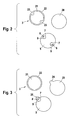
- Fig. 2 shows an embodiment for the container 3 and the associated film cut 20 and die 5 in a schematic plan view.
- the container 3 has a filling opening 21, which is surrounded by an edge 22.
- the edge 22 has two radial thickenings 23 for attaching the circular film blank 20, d. H.
- film blank 20 is provided with two tack points on container 3 fixed.
- two through holes 7 are in the punch 5 with a stamp 8 provided.
- the container 3 is in the stapling station 1 relative to Cutting punch 5 arranged such that the thickenings 23 with the stapling 8th aligned. After punching out the film blank 20 with the die 5 the two stamps 8 pressed simultaneously against the film blank 20, so that the film blank 20 is attached to the container 3 with two tacking points.
- the edge 22 of the container 3 has the same cross-section over the entire circumference.
- the film blank 20 is except for one radially projecting tab 24 is circular and is in the area of the tab 24 the container 3 pinned.
- the tab 24 is intended to pull off the seal on the container 3 Ease foil cut 20.
- the cutting punch 5 has a film cut 20 corresponding outer contour.
- the Through hole 7 is provided for the staple 8. Also in this embodiment it is necessary that the container 3 is in the correct position for the cutting punch 5 in the stapling station 1 is arranged. After the foil blank 20 has been punched out, it is removed by the Stapling stamp 8 attached to container 3 with a stapling point.
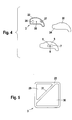
- the container 3 has a comparison with FIGS. 2 and 3 a relatively complex shape.
- a container 3 shaped in this way is used in razors and is used to store a shaving liquid.
- the shape of the container 3 is adapted to a receiving space of the shaver, in which the container 3 as one replaceable cartridge can be inserted.
- the container 3 is on its upper side largely closed and has a first opening 26 and a second opening 27, which are separated and compared to the total area of the top have relatively small dimensions.
- the rim 22, which is the top of the container 3 encloses all around, is raised and serves to establish a sealed connection with the foil blank 20.
- the openings 26 and 27 are not each be sealed for themselves, but together covered by the film blank 20 which extends over the entire top of the container 3.
- a dome-shaped elevation 28 is formed on the top of the container 3, which at Tacking the film blank 20 is melted.
- the film blank 20 is with the Cutting punch 5 punched out so that it is flush with the edge 22 except for a partial area of the container 3 completes. In the partial area, the film blank 20 is above the edge 22 of the container 3 to, according to the embodiment of FIG. 3, the tab 24 form, which facilitates the removal of the film blank 20 from the container 3.
- the container 3 in the stapling station 1 in the correct position for the cutting stamp 5 is arranged.
- the foil blank 20 After the foil blank 20 has been punched out, it is also cut a tack point in the area of the elevation 28 attached to the container 3. For this is the lateral position of the stamp 8 on the position of the elevation 28 on the top of the Container 3 matched.
- Fig. 5 shows an embodiment in which the container 3 is formed in two parts.
- the Foil blank 20 and the cutting punch 5 are not special in this embodiment shown. However, their training results in analogy to the exemplary embodiments 2, 3 and 4 directly from the geometry of the container 3.
- the container 3rd has a first partial container 29 and a second partial container 30, which by means of a Connecting web 31 are interconnected. After arranging the Container 3 in the stapling station 1 and the punching out of the film blank 20 becomes the film blank 20 in this embodiment by one or more tacking points in the Area of the connecting web 31 attached to the container 3.
- containers 3 are preferably used which are made of a plastic material, are made in particular of polypropylene.
- the film strip 12 acts it is usually a single or multiple coated metal foil.
- the coating has at least one hot melt adhesive or film, which during the Sealing process intimately connects to the container 3.
Landscapes
- Engineering & Computer Science (AREA)
- Mechanical Engineering (AREA)
- Closing Of Containers (AREA)
Abstract
Description
- Fig. 1
- ein Ausführungsbeispiel der erfindungsgemäßen Siegelvorrichtung in einer schematischen Seitenansicht,
- Fig. 2, 3, 4
- verschiedene Ausführungsbeispiele für den Behälter sowie jeweils den zugehörigen Folienzuschnitt und Schnittstempel in einer schematischen Aufsicht und
- Fig. 5
- ein weiteres Ausführungsbeispiel für den Behälter in einer schematischen Aufsicht.
Claims (22)
- Verfahren zum Versiegeln von Behältern (3) mittels Zuschnitten (20) aus einem bahnförmigen Material, wobeieine Materialbahn (12) benachbart zu dem jeweils zu versiegelnden Behälter (3) positioniert wird,der Zuschnitt (20) aus der Materialbahn (12) herausgetrennt wird,der Zuschnitt (20) an den Behälter (3) angeheftet wird undeine Siegelverbindung zwischen dem Zuschnitt (20) und dem Behälter (3) ausgebildet wird, die den zu versiegelnden Bereich des Behälters (3) umschließt.
- Verfahren nach Anspruch 1, dadurch gekennzeichnet, daß die Materialbahn (12) von einer Abrolleinrichtung (13) abgewickelt wird und der nach dem Heraustrennen der Zuschnitte (20) verbleibende Rest der Materialbahn (12) auf eine Aufrolleinrichtung (14) aufgewickelt wird.
- Verfahren nach einem der vorhergehenden Ansprüche, dadurch gekennzeichnet, daß der Zuschnitt (20) nach dem Heraustrennen mit einem für das Heraustrennen eingesetzten Trennwerkzeug (5) gegen den Behälter (3) gedrückt wird und auf diese Weise während des Anheftens des Zuschnitts (20) an den Behälter (3) ortsfest fixiert wird.
- Verfahren nach einem der vorhergehenden Ansprüche, dadurch gekennzeichnet, daß der Zuschnitt (20) durch eine lokale Einwirkung von Druck und Wärme an den Behälter (3) angeheftet wird.
- Verfahren nach einem der vorhergehenden Ansprüche, dadurch gekennzeichnet, daß der Zuschnitt (20) mit einem Heftwerkzeug (8) an den Behälter (3) angeheftet wird, das in das Trennwerkzeug (5) integriert ist.
- Verfahren nach einem der vorhergehenden Ansprüche, dadurch gekennzeichnet, daß das Heftwerkzeug (8) nach dem Anheften des Zuschnitts (20) an den Behälter (3) wenigstens partiell aus dem Trennwerkzeug (5) herausgefahren wird.
- Verfahren nach einem der vorhergehenden Ansprüche, dadurch gekennzeichnet, daß der Zuschnitt (20) aus der Materialbahn (12) ausgestanzt wird.
- Verfahren nach Anspruch 7, dadurch gekennzeichnet, daß der Behälter (3) während des Ausstanzens des Zuschnitts (20) aus der Materialbahn (12) in einer Aufnahmebohrung (10) einer beim Stanzvorgang eingesetzten Schnittplatte (6) angeordnet ist.
- Verfahren nach einem der vorhergehenden Ansprüche, dadurch gekennzeichnet, daß die Siegelverbindung in einer separaten Arbeitsstation (2) ausgebildet wird, zu der der Behälter (3) nach dem Anheften des Zuschnitts (20) transportiert wird.
- Verfahren nach einem der vorhergehenden Ansprüche, dadurch gekennzeichnet, daß zur Ausbildung der Siegelverbindung ein beheizbares Siegelwerkzeug (16) gegen den an den Behälter (3) angehefteten Zuschnitt (20) gepreßt wird.
- Verfahren nach einem der vorhergehenden Ansprüche, dadurch gekennzeichnet, daß der Behälter (3) aus Kunststoff, insbesondere aus Polypropylen gefertigt ist.
- Verfahren nach einem der vorhergehenden Ansprüche, dadurch gekennzeichnet, daß der Behälter (3) als eine Kartusche ausgebildet und mit einer Rasierflüssigkeit gefüllt ist.
- Verfahren nach einem der vorhergehenden Ansprüche, dadurch gekennzeichnet, daß als Materialbahn (12) eine Folie, insbesondere eine Metallfolie verwendet wird.
- Verfahren nach einem der vorhergehenden Ansprüche, dadurch gekennzeichnet, daß die Materialbahn (12) wenigstens eine Beschichtung aufweist.
- Verfahren nach Anspruch 14, dadurch gekennzeichnet, daß die Beschichtung wenigstens einen thermoaktivierbaren Klebstoff enthält.
- Verfahren nach Anspruch 14, dadurch gekennzeichnet, daß die Beschichtung wenigstens eine coextrudierte oder andersartig aufgebrachte Folie ist.
- Vorrichtung zum Versiegeln von Behältern (3) mittels Zuschnitten (20) aus einem bahnförmigen Material, dadurch gekennzeichnet, daß ein Schnittwerkzeug (5) zum Heraustrennen des Zuschnitts (20) aus einer Materialbahn (12) vorgesehen ist, in das ein Heftwerkzeug (8) zum Anheften des Zuschnitts (20) an den Behälter (3) integriert ist.
- Vorrichtung nach Anspruch 17, dadurch gekennzeichnet, daß das Schnittwerkzeug (5) als ein Schnittstempel ausgebildet ist und wenigstens eine Ausnehmung (7) aufweist, in der ein beheizbarer Heftstempel als Heftwerkzeug (8) verschiebbar angeordnet ist.
- Vorrichtung nach einem der Ansprüche 17 oder18, dadurch gekennzeichnet, daß das Heftwerkzeug (8) zum Schnittwerkzeug (5) thermisch isoliert ist.
- Vorrichtung nach Anspruch 19, dadurch gekennzeichnet, daß das Heftwerkzeug (8) durch einen Luftspalt (9) thermisch isoliert ist.
- Vorrichtung nach einem der Ansprüche 17 bis 20, dadurch gekennzeichnet, daß eine Heftstation (1) vorgesehen ist, in der das Schnittwerkzeug (5) mit dem integrierten Heftwerkzeug (8) angeordnet ist und eine Siegelstation (2), in der ein Siegelwerkzeug (16) zum Herstellen einer Siegelverbindung zwischen dem Zuschnitt (20) und dem Behälter (3) angeordnet ist.
- Vorrichtung nach Anspruch 21, dadurch gekennzeichnet, daß das Siegelwerkzeug (16) als ein beheizbarer Siegelstempel zum Herstellen einer Heißsiegelverbindung ausgebildet ist.
Applications Claiming Priority (2)
| Application Number | Priority Date | Filing Date | Title |
|---|---|---|---|
| DE10256572 | 2002-12-04 | ||
| DE2002156572 DE10256572A1 (de) | 2002-12-04 | 2002-12-04 | Verfahren und Vorrichtung zum Versiegeln von Behältern mit einem bahnförmigen Material |
Publications (2)
| Publication Number | Publication Date |
|---|---|
| EP1426295A1 true EP1426295A1 (de) | 2004-06-09 |
| EP1426295B1 EP1426295B1 (de) | 2007-01-10 |
Family
ID=32308964
Family Applications (1)
| Application Number | Title | Priority Date | Filing Date |
|---|---|---|---|
| EP20030027232 Expired - Lifetime EP1426295B1 (de) | 2002-12-04 | 2003-11-28 | Verfahren und Vorrichtung zum Versiegeln von Behältern mit einem bahnförmigen Material |
Country Status (2)
| Country | Link |
|---|---|
| EP (1) | EP1426295B1 (de) |
| DE (2) | DE10256572A1 (de) |
Citations (6)
| Publication number | Priority date | Publication date | Assignee | Title |
|---|---|---|---|---|
| GB1289298A (de) * | 1968-10-18 | 1972-09-13 | ||
| US4930288A (en) * | 1987-05-08 | 1990-06-05 | Benz & Hilgers Gmbh | Device for sealing foil covers onto containers, particularly plastic cups |
| US5363629A (en) * | 1992-03-03 | 1994-11-15 | Serac France | Device for closing receptacles by welding on lids, and installation including the same |
| DE19623133A1 (de) * | 1995-06-23 | 1997-01-02 | Siegfried Frei | Aus einer Aluminiumfolie bestehender Aufreißdeckel und Verfahren zur Herstellung eines Aufreißdeckels |
| DE19629356A1 (de) * | 1996-07-20 | 1998-01-22 | Willi Stenzel | Vorrichtung und Verfahren zum Heißversiegeln von Behälteröffnungen mittels Folienzuschnitten |
| DE19750075A1 (de) * | 1997-11-12 | 1999-05-27 | Benhil Gasti Verpackungsmaschi | Verfahren und Vorrichtung zum Herstellen und Aufbringen von Deckeln aus einer Werkstoffbahn, insbesondere Deckblattfolien aus einer dünnen Kunststoffolienbahn |
-
2002
- 2002-12-04 DE DE2002156572 patent/DE10256572A1/de not_active Ceased
-
2003
- 2003-11-28 DE DE50306249T patent/DE50306249D1/de not_active Expired - Lifetime
- 2003-11-28 EP EP20030027232 patent/EP1426295B1/de not_active Expired - Lifetime
Patent Citations (6)
| Publication number | Priority date | Publication date | Assignee | Title |
|---|---|---|---|---|
| GB1289298A (de) * | 1968-10-18 | 1972-09-13 | ||
| US4930288A (en) * | 1987-05-08 | 1990-06-05 | Benz & Hilgers Gmbh | Device for sealing foil covers onto containers, particularly plastic cups |
| US5363629A (en) * | 1992-03-03 | 1994-11-15 | Serac France | Device for closing receptacles by welding on lids, and installation including the same |
| DE19623133A1 (de) * | 1995-06-23 | 1997-01-02 | Siegfried Frei | Aus einer Aluminiumfolie bestehender Aufreißdeckel und Verfahren zur Herstellung eines Aufreißdeckels |
| DE19629356A1 (de) * | 1996-07-20 | 1998-01-22 | Willi Stenzel | Vorrichtung und Verfahren zum Heißversiegeln von Behälteröffnungen mittels Folienzuschnitten |
| DE19750075A1 (de) * | 1997-11-12 | 1999-05-27 | Benhil Gasti Verpackungsmaschi | Verfahren und Vorrichtung zum Herstellen und Aufbringen von Deckeln aus einer Werkstoffbahn, insbesondere Deckblattfolien aus einer dünnen Kunststoffolienbahn |
Also Published As
| Publication number | Publication date |
|---|---|
| DE10256572A1 (de) | 2004-07-08 |
| EP1426295B1 (de) | 2007-01-10 |
| DE50306249D1 (de) | 2007-02-22 |
Similar Documents
| Publication | Publication Date | Title |
|---|---|---|
| DE69006124T2 (de) | Verfahren und Vorrichtung zur Herstellung eines Ringes für einen Behälterverschluss. | |
| EP0712675B1 (de) | Vorrichtung zum Herstellen und Anbringen eines Schutzbezuges bei einer Öffnung in einer Behälterwandlung | |
| DE2553281C3 (de) | Verfahren zur Herstellung eines Behälterstirnwandverschlusses | |
| DE2841887A1 (de) | Deckel, insbesondere aus metallblech und verfahren zu seiner herstellung | |
| DE3123766C2 (de) | Vorrichtung zum Ausschneiden einer Membran aus einer Folienbahn und zum Einsetzen der Membran in einen Deckel | |
| EP0915026A1 (de) | Verfahren zur Herstellung eines Bandes aus Dichtscheibenmaterial sowie ein solches Band | |
| DE2541912C2 (de) | Behälter, insbesondere Verpackungsbehälter, sowie Verfahren zum Herstellen eines solchen Behälters und Vorrichtung zum Durchführen des Verfahrens | |
| EP1481789A2 (de) | Verfahren und Vorrichtung zur Herstellung von Verpackungsbehältern aus Kunststoff, Verpackungsmaschine und Verpackungsbehälter | |
| WO2018054695A1 (de) | Vorrichtung zum verbinden von zwei behälterteilen | |
| DE102017131026A1 (de) | Verbesserte Quertrennschweißeinrichtung, Folienverpackungsmaschine und Verfahren | |
| EP2208554B1 (de) | Verfahren und Vorrichtung zur Herstellung von Aufreissdeckeln | |
| DE102007027389A1 (de) | Verfahren und Vorrichtung zum Versiegeln von Behältern, insbesondere in der Lebensmittelverpackungsindustrie | |
| EP4228976B1 (de) | Dosendeckel und verfahren zum herstellen eines dosendeckels | |
| EP0819086A1 (de) | Dose mit einer verschlussmembran aus folie, sowie verfahren, vorrichtung und folie zur herstellung der dose | |
| EP1426295B1 (de) | Verfahren und Vorrichtung zum Versiegeln von Behältern mit einem bahnförmigen Material | |
| DE2718574A1 (de) | Dichtverschluss fuer einen fluessigkeitsbehaelter und verfahren und vorrichtung zu seiner herstellung | |
| DE4411925A1 (de) | Verfahren zum Abdecken einer Schnittkante einer Öffnung eines Behälters mit einem Schutzbezug | |
| DE3138442A1 (de) | Verfahren zum kaschieren von formteilen und vorrichtung zur durchfuehrung des verfahrens | |
| EP1819501B1 (de) | Siegelmaschine und verfahren | |
| EP0746473B1 (de) | Verfahren und vorrichtung zur herstellung von schaumstoff-dekorplatten | |
| EP1568451B1 (de) | Verfahren und Vorrichtung zum Stanzen eines Filtermaterials | |
| EP3722097B1 (de) | Verfahren zur herstellung und lackierung von auf nummernschildern gedrückten zeichen und schlauchförmiger thermotransferfilm zur durchführung des verfahrens | |
| EP2789449B1 (de) | Verfahren zum Versiegeln der Öffnung eines Bauteils, Trägerfolie mit Siegelmembran und Versiegelungsvorrichtung | |
| WO2010130361A1 (de) | Dose, verfahren zur herstellung einer verschlusseinheit für eine dose und vorrichtung zur herstellung einer solchen verschlusseinheit | |
| DE3875063T2 (de) | Verfahren und vorrichtung zum anbringen von endplatten an verpackungen. |
Legal Events
| Date | Code | Title | Description |
|---|---|---|---|
| PUAI | Public reference made under article 153(3) epc to a published international application that has entered the european phase |
Free format text: ORIGINAL CODE: 0009012 |
|
| 17P | Request for examination filed |
Effective date: 20040117 |
|
| AK | Designated contracting states |
Kind code of ref document: A1 Designated state(s): AT BE BG CH CY CZ DE DK EE ES FI FR GB GR HU IE IT LI LU MC NL PT RO SE SI SK TR |
|
| AX | Request for extension of the european patent |
Extension state: AL LT LV MK |
|
| AKX | Designation fees paid |
Designated state(s): AT BE BG CH CY CZ DE DK EE ES FI FR GB GR HU IE IT LI LU MC NL PT RO SE SI SK TR |
|
| GRAP | Despatch of communication of intention to grant a patent |
Free format text: ORIGINAL CODE: EPIDOSNIGR1 |
|
| GRAS | Grant fee paid |
Free format text: ORIGINAL CODE: EPIDOSNIGR3 |
|
| GRAA | (expected) grant |
Free format text: ORIGINAL CODE: 0009210 |
|
| AK | Designated contracting states |
Kind code of ref document: B1 Designated state(s): AT BE BG CH CY CZ DE DK EE ES FI FR GB GR HU IE IT LI LU MC NL PT RO SE SI SK TR |
|
| PG25 | Lapsed in a contracting state [announced via postgrant information from national office to epo] |
Ref country code: FI Free format text: LAPSE BECAUSE OF FAILURE TO SUBMIT A TRANSLATION OF THE DESCRIPTION OR TO PAY THE FEE WITHIN THE PRESCRIBED TIME-LIMIT Effective date: 20070110 Ref country code: DK Free format text: LAPSE BECAUSE OF FAILURE TO SUBMIT A TRANSLATION OF THE DESCRIPTION OR TO PAY THE FEE WITHIN THE PRESCRIBED TIME-LIMIT Effective date: 20070110 Ref country code: SI Free format text: LAPSE BECAUSE OF FAILURE TO SUBMIT A TRANSLATION OF THE DESCRIPTION OR TO PAY THE FEE WITHIN THE PRESCRIBED TIME-LIMIT Effective date: 20070110 Ref country code: NL Free format text: LAPSE BECAUSE OF FAILURE TO SUBMIT A TRANSLATION OF THE DESCRIPTION OR TO PAY THE FEE WITHIN THE PRESCRIBED TIME-LIMIT Effective date: 20070110 |
|
| REG | Reference to a national code |
Ref country code: GB Ref legal event code: FG4D Free format text: NOT ENGLISH |
|
| GBT | Gb: translation of ep patent filed (gb section 77(6)(a)/1977) |
Effective date: 20070110 |
|
| REG | Reference to a national code |
Ref country code: IE Ref legal event code: FG4D Free format text: LANGUAGE OF EP DOCUMENT: GERMAN |
|
| REF | Corresponds to: |
Ref document number: 50306249 Country of ref document: DE Date of ref document: 20070222 Kind code of ref document: P |
|
| PG25 | Lapsed in a contracting state [announced via postgrant information from national office to epo] |
Ref country code: SE Free format text: LAPSE BECAUSE OF FAILURE TO SUBMIT A TRANSLATION OF THE DESCRIPTION OR TO PAY THE FEE WITHIN THE PRESCRIBED TIME-LIMIT Effective date: 20070410 |
|
| PG25 | Lapsed in a contracting state [announced via postgrant information from national office to epo] |
Ref country code: BG Free format text: LAPSE BECAUSE OF EXPIRATION OF PROTECTION Effective date: 20070411 |
|
| PG25 | Lapsed in a contracting state [announced via postgrant information from national office to epo] |
Ref country code: ES Free format text: LAPSE BECAUSE OF FAILURE TO SUBMIT A TRANSLATION OF THE DESCRIPTION OR TO PAY THE FEE WITHIN THE PRESCRIBED TIME-LIMIT Effective date: 20070421 |
|
| PG25 | Lapsed in a contracting state [announced via postgrant information from national office to epo] |
Ref country code: PT Free format text: LAPSE BECAUSE OF FAILURE TO SUBMIT A TRANSLATION OF THE DESCRIPTION OR TO PAY THE FEE WITHIN THE PRESCRIBED TIME-LIMIT Effective date: 20070611 |
|
| NLV1 | Nl: lapsed or annulled due to failure to fulfill the requirements of art. 29p and 29m of the patents act | ||
| EN | Fr: translation not filed | ||
| PLBE | No opposition filed within time limit |
Free format text: ORIGINAL CODE: 0009261 |
|
| STAA | Information on the status of an ep patent application or granted ep patent |
Free format text: STATUS: NO OPPOSITION FILED WITHIN TIME LIMIT |
|
| PG25 | Lapsed in a contracting state [announced via postgrant information from national office to epo] |
Ref country code: SK Free format text: LAPSE BECAUSE OF FAILURE TO SUBMIT A TRANSLATION OF THE DESCRIPTION OR TO PAY THE FEE WITHIN THE PRESCRIBED TIME-LIMIT Effective date: 20070110 |
|
| 26N | No opposition filed |
Effective date: 20071011 |
|
| PG25 | Lapsed in a contracting state [announced via postgrant information from national office to epo] |
Ref country code: RO Free format text: LAPSE BECAUSE OF FAILURE TO SUBMIT A TRANSLATION OF THE DESCRIPTION OR TO PAY THE FEE WITHIN THE PRESCRIBED TIME-LIMIT Effective date: 20070110 Ref country code: CZ Free format text: LAPSE BECAUSE OF FAILURE TO SUBMIT A TRANSLATION OF THE DESCRIPTION OR TO PAY THE FEE WITHIN THE PRESCRIBED TIME-LIMIT Effective date: 20070110 |
|
| PG25 | Lapsed in a contracting state [announced via postgrant information from national office to epo] |
Ref country code: FR Free format text: LAPSE BECAUSE OF FAILURE TO SUBMIT A TRANSLATION OF THE DESCRIPTION OR TO PAY THE FEE WITHIN THE PRESCRIBED TIME-LIMIT Effective date: 20070831 Ref country code: IT Free format text: LAPSE BECAUSE OF FAILURE TO SUBMIT A TRANSLATION OF THE DESCRIPTION OR TO PAY THE FEE WITHIN THE PRESCRIBED TIME-LIMIT Effective date: 20070110 Ref country code: GR Free format text: LAPSE BECAUSE OF FAILURE TO SUBMIT A TRANSLATION OF THE DESCRIPTION OR TO PAY THE FEE WITHIN THE PRESCRIBED TIME-LIMIT Effective date: 20070411 |
|
| BERE | Be: lapsed |
Owner name: BRAUN G.M.B.H. Effective date: 20071130 |
|
| PG25 | Lapsed in a contracting state [announced via postgrant information from national office to epo] |
Ref country code: MC Free format text: LAPSE BECAUSE OF NON-PAYMENT OF DUE FEES Effective date: 20071130 |
|
| PG25 | Lapsed in a contracting state [announced via postgrant information from national office to epo] |
Ref country code: BE Free format text: LAPSE BECAUSE OF NON-PAYMENT OF DUE FEES Effective date: 20071130 |
|
| PG25 | Lapsed in a contracting state [announced via postgrant information from national office to epo] |
Ref country code: FR Free format text: LAPSE BECAUSE OF FAILURE TO SUBMIT A TRANSLATION OF THE DESCRIPTION OR TO PAY THE FEE WITHIN THE PRESCRIBED TIME-LIMIT Effective date: 20070110 |
|
| PG25 | Lapsed in a contracting state [announced via postgrant information from national office to epo] |
Ref country code: EE Free format text: LAPSE BECAUSE OF FAILURE TO SUBMIT A TRANSLATION OF THE DESCRIPTION OR TO PAY THE FEE WITHIN THE PRESCRIBED TIME-LIMIT Effective date: 20070110 |
|
| PG25 | Lapsed in a contracting state [announced via postgrant information from national office to epo] |
Ref country code: CY Free format text: LAPSE BECAUSE OF FAILURE TO SUBMIT A TRANSLATION OF THE DESCRIPTION OR TO PAY THE FEE WITHIN THE PRESCRIBED TIME-LIMIT Effective date: 20070110 |
|
| PG25 | Lapsed in a contracting state [announced via postgrant information from national office to epo] |
Ref country code: LU Free format text: LAPSE BECAUSE OF NON-PAYMENT OF DUE FEES Effective date: 20071128 |
|
| PG25 | Lapsed in a contracting state [announced via postgrant information from national office to epo] |
Ref country code: HU Free format text: LAPSE BECAUSE OF FAILURE TO SUBMIT A TRANSLATION OF THE DESCRIPTION OR TO PAY THE FEE WITHIN THE PRESCRIBED TIME-LIMIT Effective date: 20070711 Ref country code: TR Free format text: LAPSE BECAUSE OF FAILURE TO SUBMIT A TRANSLATION OF THE DESCRIPTION OR TO PAY THE FEE WITHIN THE PRESCRIBED TIME-LIMIT Effective date: 20070110 |
|
| PGFP | Annual fee paid to national office [announced via postgrant information from national office to epo] |
Ref country code: AT Payment date: 20101022 Year of fee payment: 8 Ref country code: IE Payment date: 20101028 Year of fee payment: 8 |
|
| PGFP | Annual fee paid to national office [announced via postgrant information from national office to epo] |
Ref country code: CH Payment date: 20101027 Year of fee payment: 8 Ref country code: DE Payment date: 20101130 Year of fee payment: 8 |
|
| PGFP | Annual fee paid to national office [announced via postgrant information from national office to epo] |
Ref country code: GB Payment date: 20101022 Year of fee payment: 8 |
|
| REG | Reference to a national code |
Ref country code: CH Ref legal event code: PL |
|
| GBPC | Gb: european patent ceased through non-payment of renewal fee |
Effective date: 20111128 |
|
| PG25 | Lapsed in a contracting state [announced via postgrant information from national office to epo] |
Ref country code: LI Free format text: LAPSE BECAUSE OF NON-PAYMENT OF DUE FEES Effective date: 20111130 Ref country code: CH Free format text: LAPSE BECAUSE OF NON-PAYMENT OF DUE FEES Effective date: 20111130 |
|
| REG | Reference to a national code |
Ref country code: IE Ref legal event code: MM4A |
|
| REG | Reference to a national code |
Ref country code: DE Ref legal event code: R119 Ref document number: 50306249 Country of ref document: DE Effective date: 20120601 |
|
| PG25 | Lapsed in a contracting state [announced via postgrant information from national office to epo] |
Ref country code: IE Free format text: LAPSE BECAUSE OF NON-PAYMENT OF DUE FEES Effective date: 20111128 Ref country code: GB Free format text: LAPSE BECAUSE OF NON-PAYMENT OF DUE FEES Effective date: 20111128 |
|
| REG | Reference to a national code |
Ref country code: AT Ref legal event code: MM01 Ref document number: 351129 Country of ref document: AT Kind code of ref document: T Effective date: 20111128 |
|
| PG25 | Lapsed in a contracting state [announced via postgrant information from national office to epo] |
Ref country code: AT Free format text: LAPSE BECAUSE OF NON-PAYMENT OF DUE FEES Effective date: 20111128 |
|
| PG25 | Lapsed in a contracting state [announced via postgrant information from national office to epo] |
Ref country code: DE Free format text: LAPSE BECAUSE OF NON-PAYMENT OF DUE FEES Effective date: 20120601 |