EP1426243A1 - Sitzkonsole für einen Fahrzeugsitz - Google Patents
Sitzkonsole für einen Fahrzeugsitz Download PDFInfo
- Publication number
- EP1426243A1 EP1426243A1 EP03020220A EP03020220A EP1426243A1 EP 1426243 A1 EP1426243 A1 EP 1426243A1 EP 03020220 A EP03020220 A EP 03020220A EP 03020220 A EP03020220 A EP 03020220A EP 1426243 A1 EP1426243 A1 EP 1426243A1
- Authority
- EP
- European Patent Office
- Prior art keywords
- frame
- seat
- upper frame
- sensors
- legs
- Prior art date
- Legal status (The legal status is an assumption and is not a legal conclusion. Google has not performed a legal analysis and makes no representation as to the accuracy of the status listed.)
- Granted
Links
Images


Classifications
-
- B—PERFORMING OPERATIONS; TRANSPORTING
- B60—VEHICLES IN GENERAL
- B60R—VEHICLES, VEHICLE FITTINGS, OR VEHICLE PARTS, NOT OTHERWISE PROVIDED FOR
- B60R21/00—Arrangements or fittings on vehicles for protecting or preventing injuries to occupants or pedestrians in case of accidents or other traffic risks
- B60R21/01—Electrical circuits for triggering passive safety arrangements, e.g. airbags, safety belt tighteners, in case of vehicle accidents or impending vehicle accidents
- B60R21/015—Electrical circuits for triggering passive safety arrangements, e.g. airbags, safety belt tighteners, in case of vehicle accidents or impending vehicle accidents including means for detecting the presence or position of passengers, passenger seats or child seats, and the related safety parameters therefor, e.g. speed or timing of airbag inflation in relation to occupant position or seat belt use
- B60R21/01512—Passenger detection systems
- B60R21/01516—Passenger detection systems using force or pressure sensing means
-
- B—PERFORMING OPERATIONS; TRANSPORTING
- B60—VEHICLES IN GENERAL
- B60N—SEATS SPECIALLY ADAPTED FOR VEHICLES; VEHICLE PASSENGER ACCOMMODATION NOT OTHERWISE PROVIDED FOR
- B60N2/00—Seats specially adapted for vehicles; Arrangement or mounting of seats in vehicles
- B60N2/002—Seats provided with an occupancy detection means mounted therein or thereon
- B60N2/0021—Seats provided with an occupancy detection means mounted therein or thereon characterised by the type of sensor or measurement
- B60N2/0024—Seats provided with an occupancy detection means mounted therein or thereon characterised by the type of sensor or measurement for identifying, categorising or investigation of the occupant or object on the seat
- B60N2/0025—Seats provided with an occupancy detection means mounted therein or thereon characterised by the type of sensor or measurement for identifying, categorising or investigation of the occupant or object on the seat by using weight measurement
-
- B—PERFORMING OPERATIONS; TRANSPORTING
- B60—VEHICLES IN GENERAL
- B60N—SEATS SPECIALLY ADAPTED FOR VEHICLES; VEHICLE PASSENGER ACCOMMODATION NOT OTHERWISE PROVIDED FOR
- B60N2/00—Seats specially adapted for vehicles; Arrangement or mounting of seats in vehicles
- B60N2/002—Seats provided with an occupancy detection means mounted therein or thereon
- B60N2/0021—Seats provided with an occupancy detection means mounted therein or thereon characterised by the type of sensor or measurement
- B60N2/003—Seats provided with an occupancy detection means mounted therein or thereon characterised by the type of sensor or measurement characterised by the sensor mounting location in or on the seat
- B60N2/0031—Seats provided with an occupancy detection means mounted therein or thereon characterised by the type of sensor or measurement characterised by the sensor mounting location in or on the seat mounted on the frame
-
- G—PHYSICS
- G01—MEASURING; TESTING
- G01G—WEIGHING
- G01G19/00—Weighing apparatus or methods adapted for special purposes not provided for in the preceding groups
- G01G19/40—Weighing apparatus or methods adapted for special purposes not provided for in the preceding groups with provisions for indicating, recording, or computing price or other quantities dependent on the weight
- G01G19/413—Weighing apparatus or methods adapted for special purposes not provided for in the preceding groups with provisions for indicating, recording, or computing price or other quantities dependent on the weight using electromechanical or electronic computing means
- G01G19/414—Weighing apparatus or methods adapted for special purposes not provided for in the preceding groups with provisions for indicating, recording, or computing price or other quantities dependent on the weight using electromechanical or electronic computing means using electronic computing means only
- G01G19/4142—Weighing apparatus or methods adapted for special purposes not provided for in the preceding groups with provisions for indicating, recording, or computing price or other quantities dependent on the weight using electromechanical or electronic computing means using electronic computing means only for controlling activation of safety devices, e.g. airbag systems
Definitions
- the invention relates to a seat console for a vehicle seat according to the preamble of claim 1.
- DE 698 02 109 T 2 describes a system for determining the weight of a Vehicle occupant is known in the between a seat rail and a seat frame Weight sensors are arranged.
- DE 100 60 649 A1 describes the arrangement of known front and rear weight sensors in vehicle seats.
- the object of the invention is to provide a seat console for a vehicle seat create, which is easy to assemble, an encapsulation of the weight sensors has and ensures trouble-free weight measurement of a vehicle occupant.
- the seat console essentially consisting of an upper frame and a lower frame torsionally stiff with intermediate sensors.
- the Seat console a fixed subframe with an interposition of Weight sensors floating upper frame.
- the weight sensors are via connecting elements on the one hand stationary with the upper frame and on the other hand attached to the subframe using a bolt integrated in the respective sensor.
- the upper and lower frames are each U-shaped in cross section formed, wherein the upper frame dips into the lower frame and the sensors are each surrounded by the side profile legs of the upper and lower frame.
- the upper and lower frames are each U-shaped in cross section, wherein the upper frame with its legs the legs of the lower frame from the outside floating overlaps. Due to this U-shaped design of the two frames Seat console, the intermediate weight sensors can send a trouble-free signal deliver, which is analyzed by an electrical control.
- the lower and upper frame has a U-profile shape
- the each has a sensor at its free ends and the others Sensors arranged in the transition area of the legs of the U-profile shape to the crossbar are.
- This arrangement of the sensors means that this is applied to a vehicle seat To determine total weight optimally.
- the The lower and upper frame also have a closed U-profile shape, that is, the Legs are each connected to a crossbar at the free end.
- spacers are arranged between the sensors and the upper frame, what possible inequalities should be corrected.
- spacers are, for example, in different thickness adapted to the particular circumstances, executed so that in in any case, no falsification of the total weight determined by the four sensors of the occupant.
- the sensors arranged in the leg on the upper frame via two threaded bolts in one of the upper sides of the upper frame arranged threaded plate are screwed.
- the further sensors arranged in the transition area are, for example, by means of Threaded bolts can be fastened in nuts held stationary in the upper frame. These nuts due to the definition in the wall of the upper frame one against one attached threaded plate lower overall height.
- the seat console By designing the seat console with mutually mutually exclusive profiles objects in the vehicle can neither block the measuring path of the weight sensors still hinder the floating mounting of the upper frame to the lower frame.
- the sensor system is also protected. Due to the direct screw-on points of the Sensors on the frame of the seat console minimize measurement errors.
- the U shape of the The upper and lower frame is advantageous because there is leg room in the rear area of the vehicle can be maintained.
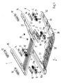
- a seat bracket 1 for a vehicle essentially comprises one with the vehicle firmly connected subframe 2 and an upper frame 3. Between the lower and Several weight sensors 4 to 7 are arranged in the upper frame 2, 3. These are firm connected to the upper frame 3 and held on the lower frame 2.
- the Upper frame 3 floating on the lower frame 2 with the interposition of the Weight sensors 4 to 7 arranged.
- sensors 4 to 7 are above one Bolt 8 supported on the subframe 2, which with its head 9 on a measuring element in Sensor acts.
- About two spaced threaded bolts 10, 11 and 10a, 11a are the Sensors 4 to 7 fixed by means of a threaded plate 12, 13 on the upper frame 3, what 2 and in details X and Z of FIGS. 4 and 5. So that one Compensation for a parallel arrangement of the upper frame 3 to the lower frame 2 possible so-called spacers 14, 15 different thickness arranged.
- the lower frame 2 and the upper frame 3 consist in cross section of a U-profile, 3 shows and the lateral profile legs S1, S2 of the two frames 2 and 3 overlap, the legs S1 of the upper frame 3 being spaced slightly apart are located within the legs S2 of the subframe 2. After another run the legs S1 can also overlap the legs S2 from the outside.
- the upper and lower frame 3, 2 form a U-shape, with a crossbar 20, 21 in relation on the direction of travel F lies in front and the adjoining legs 22, 23 of the frame 2, 3 extend from this crosspiece to the rear against the direction of travel F.
- the weight sensors 4, 5 are at the free ends 24, 25 between the legs 22, 23 of the U-shape of the frame 3, 2 arranged.
- the other weight sensors 6, 7 are in the Transition area 26, 27 is provided between frames 2 and 3.
- the sensors 4, 5 are attached to the upper frame 3 by means of the screws 10, 11 and 10a, 11a, which are screwed to the threaded plate 12.
- the others Sensors 6, 7 are either via a threaded plate 13 or in the frame 3 inserted nuts 29 held. In the exemplary embodiment, the sensor 6 is via a Threaded plate 13 and the sensor 7 held on threaded nuts 29.
- Fig. 1 only the seat bracket 1 with the upper and lower frames 3, 2 is shown in more detail.
- the seat console 1 should be as possible have a protected arrangement for the sensors 4 to 7, for which purpose, as shown in FIG. 3, the U-profiles of the legs 22, 23 of the frames 2, 3 are nested one inside the other so that the floating arrangement of the upper frame 3 in the lower frame 2 is not hindered.
- the free ends 24, 25 of the frame 2, 3 are not closer to one shown cap or the like. Completed.
Landscapes
- Engineering & Computer Science (AREA)
- Physics & Mathematics (AREA)
- Mechanical Engineering (AREA)
- Mathematical Physics (AREA)
- Theoretical Computer Science (AREA)
- Aviation & Aerospace Engineering (AREA)
- Transportation (AREA)
- General Physics & Mathematics (AREA)
- Seats For Vehicles (AREA)
- Air Bags (AREA)
- Vehicle Waterproofing, Decoration, And Sanitation Devices (AREA)
- Vehicle Step Arrangements And Article Storage (AREA)
Abstract
Description
Es zeigen
- Fig. 1
- eine schaubildliche Darstellung der Sitzkonsole in einer Explosivdarstellung der Rahmen und Sensoren und Befestigungselemente,
- Fig. 2
- einen Vertikalschnitt durch die Schenkel des Ober- und Unterrahmens im zusammengebauten Zustand,
- Fig. 3
- einen Querschnitt durch die U-Profile des Ober- und Unterrahmens,
- Fig. 4
- einen Vertikalschnitt der Einzelheit X durch den in Bezug auf die Fahrtrichtung F hintenliegenden Sensor zwischen den Rahmenschenkeln und
- Fig. 5
- einen Vertikalschnitt der Einzelheit Z durch den in Bezug auf die Fahrtrichtung vornliegenden Sensor im Übergangsbereich vom Schenkel zum Quersteg der Rahmen.
Claims (9)
- Sitzkonsole für einen Fahrzeugsitz, welche am Fahrzeugboden gehalten und mit einer Sitzschiene verbunden und in dem der Fahrzeugsitz verschiebbar gelagert ist, dadurch gekennzeichnet, daß die Sitzkonsole (1) einen feststehenden Unterrahmen (2) mit einem unter Zwischenschaltung von Gewichtssensoren (4 bis 7) schwimmend gelagerten Oberrahmen (3) umfaßt, wobei die Gewichtssensoren (4 bis 7) über Verbindungselemente (12, 13, 29) einerseits ortsfest mit dem Oberrahmen (3) verbunden und andererseits über einen in den jeweiligen Sensoren (4 bis 7) integrierten Bolzen (8) am Unterrahmen (2) befestigt sind.
- Sitzkonsole nach Anspruch 1, dadurch gekennzeichnet, daß der Ober- und Unterrahmen (3, 2) im Querschnitt jeweils U-profilförmig ausgebildet sind, wobei der Oberrahmen (3) mit seinen Schenkeln (S1), die Schenkel (S2) des Unterrahmens (2) von außen schwimmend übergreift.
- Sitzkonsole nach Anspruch 1, dadurch gekennzeichnet, daß der Ober- und Unterrahmen (3, 2) im Querschnitt jeweils U-profilförmig ausgebildet sind, wobei der Oberrahmen (3) mit seinen Schenkeln (S1) in den Unterrahmen (2) eintaucht und die Sensoren (4 bis 7) jeweils von Schenkeln (22, 23) des Ober- und Unterrahmens (3, 2) umgeben sind.
- Sitzkonsole nach den Ansprüchen 1, 2 oder 3, dadurch gekennzeichnet, daß der Unter- und Oberrahmen (2, 3) eine U-Profilform aufweist, und die Rahmen an ihren freien Enden (24, 25) der Schenkel (23, 22) jeweils einen Sensor (4, 5) aufweisen und die weiteren Sensoren (6, 7) im Übergangsbereich (26, 27) der Schenkel (22, 23) der U-Profilform zum Quersteg (20, 21) der Rahmen angeordnet sind.
- Sitzkonsole nach den Ansprüchen 1, 2, 3 oder 4, dadurch gekennzeichnet, daß zur Erzielung einer parallelen Anordnung des Oberrahmens (3) zum Unterrahmen (2) zwischen den Sensoren (4 bis 7) und dem Oberrahmen (3) Distanzstücke (14, 15) angeordnet sind.
- Sitzkonsole nach einem der vorhergehenden Ansprüche, dadurch gekennzeichnet, daß die in den Schenkeln (22, 23) angeordneten Sensoren (4 bis 7) am Oberrahmen (3) über zwei Gewindebolzen (10, 11) bzw. (10a, 11a) in der oberseitig des Oberrahmens (3) als Verbindungselement ausgebildeten Gewindeplatte (12, 13) verschraubbar sind.
- Sitzkonsole nach einem der vorhergehenden Ansprüche, dadurch gekennzeichnet, daß die im Übergangsbereich (26) bzw. (27) angeordneten Sensoren (6, 7) mittels der Gewindebolzen (10a, 11a) in im Oberrahmen (3) ortsfestgehaltenen Muttern (29) oder der Gewindeplatte (13) befestigbar sind.
- Sitzkonsole nach einem der vorhergehenden Ansprüche, dadurch gekennzeichnet, daß die Schenkel (22, 23) des Ober- und Unterrahmens (3, 2) an ihren freien Enden (24, 25) über eine Abdeckkappe abgeschlossen sind.
- Sitzkonsole nach einem der vorhergehenden Ansprüche, dadurch gekennzeichnet, daß der Unter- und Oberrahmen (2, 3) aus einer U-Form besteht, und die freien Enden der Schenkel (24, 25) jeweils über einen Quersteg verbunden sind.
Applications Claiming Priority (2)
| Application Number | Priority Date | Filing Date | Title |
|---|---|---|---|
| DE10256741 | 2002-12-05 | ||
| DE10256741A DE10256741B3 (de) | 2002-12-05 | 2002-12-05 | Sitzkonsole für einen Fahrzeugsitz |
Publications (2)
| Publication Number | Publication Date |
|---|---|
| EP1426243A1 true EP1426243A1 (de) | 2004-06-09 |
| EP1426243B1 EP1426243B1 (de) | 2005-11-30 |
Family
ID=32308982
Family Applications (1)
| Application Number | Title | Priority Date | Filing Date |
|---|---|---|---|
| EP03020220A Expired - Lifetime EP1426243B1 (de) | 2002-12-05 | 2003-09-06 | Sitzkonsole für einen Fahrzeugsitz |
Country Status (6)
| Country | Link |
|---|---|
| US (1) | US7128181B2 (de) |
| EP (1) | EP1426243B1 (de) |
| JP (1) | JP4230315B2 (de) |
| AT (1) | ATE311314T1 (de) |
| DE (2) | DE10256741B3 (de) |
| ES (1) | ES2251658T3 (de) |
Cited By (1)
| Publication number | Priority date | Publication date | Assignee | Title |
|---|---|---|---|---|
| WO2017032606A1 (de) * | 2015-08-27 | 2017-03-02 | Rheinmetall Waffe Munition Gmbh | Vorrichtung zur anbringung eines fahrzeugsitzes |
Families Citing this family (5)
| Publication number | Priority date | Publication date | Assignee | Title |
|---|---|---|---|---|
| DE10304570B4 (de) * | 2003-02-05 | 2012-10-18 | Volkswagen Ag | Fahrersitz mit Gewichtssensorik |
| US7455343B2 (en) * | 2005-09-12 | 2008-11-25 | Ts Tech Co., Ltd. | Passenger's weight measurement device for vehicle seat and attachment structure for load sensor |
| KR100941251B1 (ko) * | 2007-12-17 | 2010-02-10 | 현대모비스 주식회사 | 독립된 프레임 구조를 가지는 승객식별장치 |
| KR102052864B1 (ko) * | 2013-10-04 | 2019-12-05 | 현대모비스 주식회사 | 차량용 승객식별장치 |
| DE202018001597U1 (de) | 2018-03-26 | 2019-07-02 | Scherdel Marienberg Gmbh | Vorrichtung zur Erfassung einer Sitzbelegung an einem Kraftfahrzeugsitz |
Citations (8)
| Publication number | Priority date | Publication date | Assignee | Title |
|---|---|---|---|---|
| US6039344A (en) | 1998-01-09 | 2000-03-21 | Trw Inc. | Vehicle occupant weight sensor apparatus |
| WO2001000454A1 (en) | 1999-06-25 | 2001-01-04 | Siemens Automotive Corporation | Weight sensor assembly for determining seat occupant weight |
| US6224094B1 (en) | 1998-05-19 | 2001-05-01 | Peter Norton | Force sensor for seat occupant weight sensor |
| US6282473B1 (en) * | 1999-12-07 | 2001-08-28 | Trw Vehicle Safety Systems Inc. | System and method for controlling a vehicle occupant protection device |
| US20020062699A1 (en) * | 2000-11-30 | 2002-05-30 | Tachi-S Co., Ltd. | Load detection structure for vehicle seat |
| WO2002043985A2 (en) | 2000-11-28 | 2002-06-06 | Siemens Automotive Corporation | Sensor assembly for measuring weight applied to a vehicle seat |
| US6419315B1 (en) * | 2000-06-01 | 2002-07-16 | Johnson Controls Technology Company | Mounting device of an occupant detection system |
| DE10120977A1 (de) | 2001-05-01 | 2002-11-14 | Bizerba Gmbh & Co Kg | Fahrzeugsitz |
Family Cites Families (21)
| Publication number | Priority date | Publication date | Assignee | Title |
|---|---|---|---|---|
| US3531795A (en) * | 1967-09-20 | 1970-09-29 | Sanders Associates Inc | Bar-type display |
| JPS57110928A (en) * | 1980-12-27 | 1982-07-10 | Sharp Corp | Thermometer |
| US4689615A (en) * | 1983-11-03 | 1987-08-25 | Hi-Speed Checkweigher Co., Inc. | Display of data source trends |
| US4629015A (en) * | 1984-11-28 | 1986-12-16 | Cobe Asdt, Inc. | Weight monitoring system |
| HUT53046A (en) * | 1988-11-03 | 1990-09-28 | Janos Bodis | Process for producing building blocks |
| US5579782A (en) * | 1993-08-12 | 1996-12-03 | Omron Corporation | Device to provide data as a guide to health management |
| ES2229224T3 (es) * | 1994-09-07 | 2005-04-16 | Omron Healthcare Co., Ltd. | Dispositivo medidor de una cantidad de ejercicio, capaz de presentar la cantidad de ejercicio que todavia ha de realizarse. |
| JP3240401B2 (ja) * | 1994-12-07 | 2001-12-17 | オムロン株式会社 | インピーダンス測定装置および健康管理指針アドバイス装置 |
| US5705747A (en) * | 1995-01-13 | 1998-01-06 | Henry Filters, Inc. | Methods and system for scaleable liquid display and control |
| US5991676A (en) * | 1996-11-22 | 1999-11-23 | Breed Automotive Technology, Inc. | Seat occupant sensing system |
| KR20010031876A (ko) * | 1997-11-12 | 2001-04-16 | 웰스 러셀 씨 | 차량 좌석 착석 승객의 중량과 위치를 결정하는 방법 및시스템 |
| US6354996B1 (en) * | 1998-04-15 | 2002-03-12 | Braun Gmbh | Body composition analyzer with trend display |
| CA2236063C (en) * | 1998-04-28 | 2005-07-12 | Ibm Canada Limited-Ibm Canada Limitee | Multi-variable graphical interface and method |
| JP3683712B2 (ja) * | 1998-06-05 | 2005-08-17 | タカタ株式会社 | シート重量計測装置 |
| US6764094B1 (en) * | 1999-06-25 | 2004-07-20 | Siemens Vdo Automotive Corporation | Weight sensor assembly for determining seat occupant weight |
| JP3722678B2 (ja) * | 1999-10-27 | 2005-11-30 | 株式会社タニタ | 体脂肪計 |
| JP4064028B2 (ja) * | 2000-01-05 | 2008-03-19 | 株式会社タニタ | 身体疲労度判定装置 |
| EP1192898B1 (de) * | 2000-10-02 | 2006-02-15 | Tanita Corporation | Gerät zur Verwaltung des weiblichen physischen Zustands |
| US6670560B2 (en) * | 2000-10-02 | 2003-12-30 | Siemens Vdo Automotive Corporation | Sensor integrated bracket for weight classification |
| DE10154231A1 (de) * | 2000-11-09 | 2002-08-01 | Hammerstein Gmbh C Rob | Nachweiseinheit für die Belegung eines Kraftfahrzeugsitzes durch einen Passagier und damit ausgerüsteter Kraftfahrzeugsitz |
| US6835899B2 (en) * | 2002-08-21 | 2004-12-28 | Trw Inc. | Load sensing assembly for a vehicle seat |
-
2002
- 2002-12-05 DE DE10256741A patent/DE10256741B3/de not_active Expired - Fee Related
-
2003
- 2003-09-01 JP JP2003308414A patent/JP4230315B2/ja not_active Expired - Fee Related
- 2003-09-06 AT AT03020220T patent/ATE311314T1/de not_active IP Right Cessation
- 2003-09-06 DE DE50301797T patent/DE50301797D1/de not_active Expired - Lifetime
- 2003-09-06 ES ES03020220T patent/ES2251658T3/es not_active Expired - Lifetime
- 2003-09-06 EP EP03020220A patent/EP1426243B1/de not_active Expired - Lifetime
- 2003-12-05 US US10/727,991 patent/US7128181B2/en not_active Expired - Lifetime
Patent Citations (8)
| Publication number | Priority date | Publication date | Assignee | Title |
|---|---|---|---|---|
| US6039344A (en) | 1998-01-09 | 2000-03-21 | Trw Inc. | Vehicle occupant weight sensor apparatus |
| US6224094B1 (en) | 1998-05-19 | 2001-05-01 | Peter Norton | Force sensor for seat occupant weight sensor |
| WO2001000454A1 (en) | 1999-06-25 | 2001-01-04 | Siemens Automotive Corporation | Weight sensor assembly for determining seat occupant weight |
| US6282473B1 (en) * | 1999-12-07 | 2001-08-28 | Trw Vehicle Safety Systems Inc. | System and method for controlling a vehicle occupant protection device |
| US6419315B1 (en) * | 2000-06-01 | 2002-07-16 | Johnson Controls Technology Company | Mounting device of an occupant detection system |
| WO2002043985A2 (en) | 2000-11-28 | 2002-06-06 | Siemens Automotive Corporation | Sensor assembly for measuring weight applied to a vehicle seat |
| US20020062699A1 (en) * | 2000-11-30 | 2002-05-30 | Tachi-S Co., Ltd. | Load detection structure for vehicle seat |
| DE10120977A1 (de) | 2001-05-01 | 2002-11-14 | Bizerba Gmbh & Co Kg | Fahrzeugsitz |
Cited By (2)
| Publication number | Priority date | Publication date | Assignee | Title |
|---|---|---|---|---|
| WO2017032606A1 (de) * | 2015-08-27 | 2017-03-02 | Rheinmetall Waffe Munition Gmbh | Vorrichtung zur anbringung eines fahrzeugsitzes |
| DE102015011057A1 (de) | 2015-08-27 | 2017-03-02 | Rheinmetall Waffe Munition Gmbh | Vorrichtung zur Anbringung eines Fahrzeugsitzes |
Also Published As
| Publication number | Publication date |
|---|---|
| JP4230315B2 (ja) | 2009-02-25 |
| JP2004184401A (ja) | 2004-07-02 |
| US7128181B2 (en) | 2006-10-31 |
| ATE311314T1 (de) | 2005-12-15 |
| DE10256741B3 (de) | 2004-07-01 |
| EP1426243B1 (de) | 2005-11-30 |
| US20040164581A1 (en) | 2004-08-26 |
| DE50301797D1 (de) | 2006-01-05 |
| ES2251658T3 (es) | 2006-05-01 |
Similar Documents
| Publication | Publication Date | Title |
|---|---|---|
| EP1153823B1 (de) | Fahrzeugaufbau für einen Vorderwagen eines Kraftfahrzeugs | |
| DE102008036335B4 (de) | Versteifungsvorrichtung | |
| EP2252475B1 (de) | Vorrichtung zum elastischen lagern einer motorgetriebeeinheit | |
| DE19954296A1 (de) | Fahrzeug | |
| DE19944684C1 (de) | Verschiebevorrichtung für Sattelkupplungen | |
| WO2014001533A1 (de) | Elektromotorischer möbelantrieb | |
| DE102018117118A1 (de) | Schiene für Fahrzeugsitz und Fahrzeugsitz umfassend eine solche Schiene | |
| EP2041533B1 (de) | Waagenvorrichtung | |
| DE102010061788A1 (de) | Vorrichtung zur Einstellung einer Lordosenstütze | |
| EP1426243B1 (de) | Sitzkonsole für einen Fahrzeugsitz | |
| EP1251038A2 (de) | Frontmodul mit Montageträger für ein Kraftfahrzeug | |
| DE102004042840A1 (de) | Kraftfahrzeugsitz mit Erfassung des Passagiergewichts | |
| DE102004053452B3 (de) | Befestigungsvorrichtung für einen Monitor an einem Fahrzeugsitz | |
| DE19533157A1 (de) | Befestigungsanordnung einer Reling auf einem Fahrzeugdach | |
| DE102011080520A1 (de) | Lordosenstütze | |
| DE19955455B4 (de) | Höhenverstellbares Pflegebett | |
| DE3906601C2 (de) | Sicherheitsrahmen für ein Zweirad | |
| DE2836579A1 (de) | Kopfstuetze | |
| AT503382A1 (de) | Untergestell für eine sanitärwanne | |
| DE10122316A1 (de) | Kraftaufnehmer zur Ermittlung der Sitzbelastung | |
| DE102004063736A1 (de) | Ladeboden für den Laderaum eines Kraftfahrzeuges | |
| EP3922510B1 (de) | Schienenführung, sitzanordnung und fahrzeug | |
| DE102022116241A1 (de) | Rollstuhl | |
| DE202008001914U1 (de) | Konsole für einen Fahrer- und einen Beifahrersitz insbesondere für ein Wohnmobil oder einen Reisebus | |
| DE102023111804A1 (de) | Elektromotorischer Doppelantrieb |
Legal Events
| Date | Code | Title | Description |
|---|---|---|---|
| PUAI | Public reference made under article 153(3) epc to a published international application that has entered the european phase |
Free format text: ORIGINAL CODE: 0009012 |
|
| AK | Designated contracting states |
Kind code of ref document: A1 Designated state(s): AT BE BG CH CY CZ DE DK EE ES FI FR GB GR HU IE IT LI LU MC NL PT RO SE SI SK TR |
|
| AX | Request for extension of the european patent |
Extension state: AL LT LV MK |
|
| TPAC | Observations filed by third parties |
Free format text: ORIGINAL CODE: EPIDOSNTIPA |
|
| 17P | Request for examination filed |
Effective date: 20041209 |
|
| AKX | Designation fees paid |
Designated state(s): AT BE BG CH CY CZ DE DK EE ES FI FR GB GR HU IE IT LI LU MC NL PT RO SE SI SK TR |
|
| 17Q | First examination report despatched |
Effective date: 20050207 |
|
| GRAP | Despatch of communication of intention to grant a patent |
Free format text: ORIGINAL CODE: EPIDOSNIGR1 |
|
| GRAS | Grant fee paid |
Free format text: ORIGINAL CODE: EPIDOSNIGR3 |
|
| GRAA | (expected) grant |
Free format text: ORIGINAL CODE: 0009210 |
|
| AK | Designated contracting states |
Kind code of ref document: B1 Designated state(s): AT BE BG CH CY CZ DE DK EE ES FI FR GB GR HU IE IT LI LU MC NL PT RO SE SI SK TR |
|
| PG25 | Lapsed in a contracting state [announced via postgrant information from national office to epo] |
Ref country code: SK Free format text: LAPSE BECAUSE OF FAILURE TO SUBMIT A TRANSLATION OF THE DESCRIPTION OR TO PAY THE FEE WITHIN THE PRESCRIBED TIME-LIMIT Effective date: 20051130 Ref country code: SI Free format text: LAPSE BECAUSE OF FAILURE TO SUBMIT A TRANSLATION OF THE DESCRIPTION OR TO PAY THE FEE WITHIN THE PRESCRIBED TIME-LIMIT Effective date: 20051130 Ref country code: RO Free format text: LAPSE BECAUSE OF FAILURE TO SUBMIT A TRANSLATION OF THE DESCRIPTION OR TO PAY THE FEE WITHIN THE PRESCRIBED TIME-LIMIT Effective date: 20051130 Ref country code: NL Free format text: LAPSE BECAUSE OF FAILURE TO SUBMIT A TRANSLATION OF THE DESCRIPTION OR TO PAY THE FEE WITHIN THE PRESCRIBED TIME-LIMIT Effective date: 20051130 Ref country code: CZ Free format text: LAPSE BECAUSE OF FAILURE TO SUBMIT A TRANSLATION OF THE DESCRIPTION OR TO PAY THE FEE WITHIN THE PRESCRIBED TIME-LIMIT Effective date: 20051130 Ref country code: FI Free format text: LAPSE BECAUSE OF FAILURE TO SUBMIT A TRANSLATION OF THE DESCRIPTION OR TO PAY THE FEE WITHIN THE PRESCRIBED TIME-LIMIT Effective date: 20051130 Ref country code: IE Free format text: LAPSE BECAUSE OF FAILURE TO SUBMIT A TRANSLATION OF THE DESCRIPTION OR TO PAY THE FEE WITHIN THE PRESCRIBED TIME-LIMIT Effective date: 20051130 |
|
| REG | Reference to a national code |
Ref country code: CH Ref legal event code: EP Ref country code: GB Ref legal event code: FG4D Free format text: NOT ENGLISH |
|
| REG | Reference to a national code |
Ref country code: IE Ref legal event code: FG4D Free format text: LANGUAGE OF EP DOCUMENT: GERMAN |
|
| REF | Corresponds to: |
Ref document number: 50301797 Country of ref document: DE Date of ref document: 20060105 Kind code of ref document: P |
|
| GBT | Gb: translation of ep patent filed (gb section 77(6)(a)/1977) |
Effective date: 20060130 |
|
| PG25 | Lapsed in a contracting state [announced via postgrant information from national office to epo] |
Ref country code: BG Free format text: LAPSE BECAUSE OF FAILURE TO SUBMIT A TRANSLATION OF THE DESCRIPTION OR TO PAY THE FEE WITHIN THE PRESCRIBED TIME-LIMIT Effective date: 20060228 Ref country code: DK Free format text: LAPSE BECAUSE OF FAILURE TO SUBMIT A TRANSLATION OF THE DESCRIPTION OR TO PAY THE FEE WITHIN THE PRESCRIBED TIME-LIMIT Effective date: 20060228 Ref country code: GR Free format text: LAPSE BECAUSE OF FAILURE TO SUBMIT A TRANSLATION OF THE DESCRIPTION OR TO PAY THE FEE WITHIN THE PRESCRIBED TIME-LIMIT Effective date: 20060228 |
|
| REG | Reference to a national code |
Ref country code: SE Ref legal event code: TRGR |
|
| RIN2 | Information on inventor provided after grant (corrected) |
Inventor name: BECHTLE, ROLF Inventor name: MEHRKENS, MICHAEL Inventor name: WALTER, SIEGFRIED Inventor name: KNOBLAUCH, THOMAS Inventor name: MEIER, STEFFEN |
|
| REG | Reference to a national code |
Ref country code: ES Ref legal event code: FG2A Ref document number: 2251658 Country of ref document: ES Kind code of ref document: T3 |
|
| PG25 | Lapsed in a contracting state [announced via postgrant information from national office to epo] |
Ref country code: PT Free format text: LAPSE BECAUSE OF FAILURE TO SUBMIT A TRANSLATION OF THE DESCRIPTION OR TO PAY THE FEE WITHIN THE PRESCRIBED TIME-LIMIT Effective date: 20060502 |
|
| NLV1 | Nl: lapsed or annulled due to failure to fulfill the requirements of art. 29p and 29m of the patents act | ||
| PG25 | Lapsed in a contracting state [announced via postgrant information from national office to epo] |
Ref country code: HU Free format text: LAPSE BECAUSE OF FAILURE TO SUBMIT A TRANSLATION OF THE DESCRIPTION OR TO PAY THE FEE WITHIN THE PRESCRIBED TIME-LIMIT Effective date: 20060601 |
|
| ET | Fr: translation filed | ||
| REG | Reference to a national code |
Ref country code: IE Ref legal event code: FD4D |
|
| PG25 | Lapsed in a contracting state [announced via postgrant information from national office to epo] |
Ref country code: BE Free format text: LAPSE BECAUSE OF NON-PAYMENT OF DUE FEES Effective date: 20060930 Ref country code: MC Free format text: LAPSE BECAUSE OF NON-PAYMENT OF DUE FEES Effective date: 20060930 |
|
| PLBE | No opposition filed within time limit |
Free format text: ORIGINAL CODE: 0009261 |
|
| STAA | Information on the status of an ep patent application or granted ep patent |
Free format text: STATUS: NO OPPOSITION FILED WITHIN TIME LIMIT |
|
| 26N | No opposition filed |
Effective date: 20060831 |
|
| PGFP | Annual fee paid to national office [announced via postgrant information from national office to epo] |
Ref country code: ES Payment date: 20070927 Year of fee payment: 5 |
|
| BERE | Be: lapsed |
Owner name: DR.ING. H.C.F. PORSCHE A.G. Effective date: 20060930 |
|
| PGFP | Annual fee paid to national office [announced via postgrant information from national office to epo] |
Ref country code: SE Payment date: 20070913 Year of fee payment: 5 |
|
| REG | Reference to a national code |
Ref country code: CH Ref legal event code: PL |
|
| PG25 | Lapsed in a contracting state [announced via postgrant information from national office to epo] |
Ref country code: EE Free format text: LAPSE BECAUSE OF FAILURE TO SUBMIT A TRANSLATION OF THE DESCRIPTION OR TO PAY THE FEE WITHIN THE PRESCRIBED TIME-LIMIT Effective date: 20051130 |
|
| PG25 | Lapsed in a contracting state [announced via postgrant information from national office to epo] |
Ref country code: CH Free format text: LAPSE BECAUSE OF NON-PAYMENT OF DUE FEES Effective date: 20070930 Ref country code: LI Free format text: LAPSE BECAUSE OF NON-PAYMENT OF DUE FEES Effective date: 20070930 Ref country code: LU Free format text: LAPSE BECAUSE OF NON-PAYMENT OF DUE FEES Effective date: 20060906 Ref country code: TR Free format text: LAPSE BECAUSE OF FAILURE TO SUBMIT A TRANSLATION OF THE DESCRIPTION OR TO PAY THE FEE WITHIN THE PRESCRIBED TIME-LIMIT Effective date: 20051130 |
|
| PG25 | Lapsed in a contracting state [announced via postgrant information from national office to epo] |
Ref country code: CY Free format text: LAPSE BECAUSE OF FAILURE TO SUBMIT A TRANSLATION OF THE DESCRIPTION OR TO PAY THE FEE WITHIN THE PRESCRIBED TIME-LIMIT Effective date: 20051130 |
|
| PGFP | Annual fee paid to national office [announced via postgrant information from national office to epo] |
Ref country code: AT Payment date: 20080915 Year of fee payment: 6 |
|
| REG | Reference to a national code |
Ref country code: ES Ref legal event code: PC2A |
|
| REG | Reference to a national code |
Ref country code: FR Ref legal event code: TP |
|
| REG | Reference to a national code |
Ref country code: ES Ref legal event code: FD2A Effective date: 20080908 |
|
| REG | Reference to a national code |
Ref country code: FR Ref legal event code: CD |
|
| PG25 | Lapsed in a contracting state [announced via postgrant information from national office to epo] |
Ref country code: ES Free format text: LAPSE BECAUSE OF NON-PAYMENT OF DUE FEES Effective date: 20080908 |
|
| PG25 | Lapsed in a contracting state [announced via postgrant information from national office to epo] |
Ref country code: AT Free format text: LAPSE BECAUSE OF NON-PAYMENT OF DUE FEES Effective date: 20090906 |
|
| PG25 | Lapsed in a contracting state [announced via postgrant information from national office to epo] |
Ref country code: SE Free format text: LAPSE BECAUSE OF NON-PAYMENT OF DUE FEES Effective date: 20080907 |
|
| REG | Reference to a national code |
Ref country code: FR Ref legal event code: TP |
|
| REG | Reference to a national code |
Ref country code: GB Ref legal event code: 732E Free format text: REGISTERED BETWEEN 20110310 AND 20110316 |
|
| REG | Reference to a national code |
Ref country code: GB Ref legal event code: 732E Free format text: REGISTERED BETWEEN 20110331 AND 20110406 |
|
| REG | Reference to a national code |
Ref country code: FR Ref legal event code: PLFP Year of fee payment: 14 |
|
| PGFP | Annual fee paid to national office [announced via postgrant information from national office to epo] |
Ref country code: GB Payment date: 20160920 Year of fee payment: 14 Ref country code: DE Payment date: 20160825 Year of fee payment: 14 |
|
| PGFP | Annual fee paid to national office [announced via postgrant information from national office to epo] |
Ref country code: FR Payment date: 20160921 Year of fee payment: 14 |
|
| PGFP | Annual fee paid to national office [announced via postgrant information from national office to epo] |
Ref country code: IT Payment date: 20160922 Year of fee payment: 14 |
|
| REG | Reference to a national code |
Ref country code: DE Ref legal event code: R119 Ref document number: 50301797 Country of ref document: DE |
|
| GBPC | Gb: european patent ceased through non-payment of renewal fee |
Effective date: 20170906 |
|
| REG | Reference to a national code |
Ref country code: FR Ref legal event code: ST Effective date: 20180531 |
|
| PG25 | Lapsed in a contracting state [announced via postgrant information from national office to epo] |
Ref country code: GB Free format text: LAPSE BECAUSE OF NON-PAYMENT OF DUE FEES Effective date: 20170906 Ref country code: DE Free format text: LAPSE BECAUSE OF NON-PAYMENT OF DUE FEES Effective date: 20180404 |
|
| PG25 | Lapsed in a contracting state [announced via postgrant information from national office to epo] |
Ref country code: FR Free format text: LAPSE BECAUSE OF NON-PAYMENT OF DUE FEES Effective date: 20171002 Ref country code: IT Free format text: LAPSE BECAUSE OF NON-PAYMENT OF DUE FEES Effective date: 20170906 |