EP1426143B1 - Clamping device, especially toggle lever clamp - Google Patents
Clamping device, especially toggle lever clamp Download PDFInfo
- Publication number
- EP1426143B1 EP1426143B1 EP03018177A EP03018177A EP1426143B1 EP 1426143 B1 EP1426143 B1 EP 1426143B1 EP 03018177 A EP03018177 A EP 03018177A EP 03018177 A EP03018177 A EP 03018177A EP 1426143 B1 EP1426143 B1 EP 1426143B1
- Authority
- EP
- European Patent Office
- Prior art keywords
- clamping device
- plug
- headpiece
- sensor
- halves
- Prior art date
- Legal status (The legal status is an assumption and is not a legal conclusion. Google has not performed a legal analysis and makes no representation as to the accuracy of the status listed.)
- Expired - Lifetime
Links
- 230000005540 biological transmission Effects 0.000 claims description 10
- 230000001939 inductive effect Effects 0.000 claims description 6
- 238000005259 measurement Methods 0.000 claims description 3
- 238000002789 length control Methods 0.000 claims 1
- 238000000926 separation method Methods 0.000 claims 1
- 238000012546 transfer Methods 0.000 abstract description 2
- 238000003780 insertion Methods 0.000 description 4
- 230000037431 insertion Effects 0.000 description 4
- 230000008054 signal transmission Effects 0.000 description 4
- 238000004519 manufacturing process Methods 0.000 description 3
- 230000001419 dependent effect Effects 0.000 description 2
- 238000013461 design Methods 0.000 description 2
- 238000011161 development Methods 0.000 description 2
- 230000018109 developmental process Effects 0.000 description 2
- 238000004891 communication Methods 0.000 description 1
- 230000006698 induction Effects 0.000 description 1
- 238000009434 installation Methods 0.000 description 1
- 238000012423 maintenance Methods 0.000 description 1
- 238000013507 mapping Methods 0.000 description 1
Images

Classifications
-
- B—PERFORMING OPERATIONS; TRANSPORTING
- B25—HAND TOOLS; PORTABLE POWER-DRIVEN TOOLS; MANIPULATORS
- B25B—TOOLS OR BENCH DEVICES NOT OTHERWISE PROVIDED FOR, FOR FASTENING, CONNECTING, DISENGAGING OR HOLDING
- B25B5/00—Clamps
- B25B5/16—Details, e.g. jaws, jaw attachments
-
- B—PERFORMING OPERATIONS; TRANSPORTING
- B25—HAND TOOLS; PORTABLE POWER-DRIVEN TOOLS; MANIPULATORS
- B25B—TOOLS OR BENCH DEVICES NOT OTHERWISE PROVIDED FOR, FOR FASTENING, CONNECTING, DISENGAGING OR HOLDING
- B25B5/00—Clamps
- B25B5/06—Arrangements for positively actuating jaws
- B25B5/12—Arrangements for positively actuating jaws using toggle links
- B25B5/122—Arrangements for positively actuating jaws using toggle links with fluid drive
Definitions
- the invention relates to a clamping device, in particular toggle lever clamping device, according to the preamble of claim 1, which is known from the document DE 297 18 644 A is known.
- a clamping device of a special kind as this is the opening angle size caused by length adjustment of the linearly movable actuator, resulting in that arranged in the end piece End thoroughlysabfragesensoren, as they may be designed in detail, not be installed variable position in the head
- the interrogation sensors do not have to be accessible from the outside, but, as far as is known and for whatever reason, this has not been practiced so far.
- the invention has for its object to remedy this, ie, jigs regarding their End einsabfrage wornen to improve and to design that always unavoidable re-occurring exchange requirements, these are not only reduced to the necessary minimum but can also be carried out quickly and easily.
- the solution according to the invention makes use, on the one hand, of the fact or knowledge that, in the case of tensioning devices with a variable-length actuator, the elements for the end position query no longer have to be installed on the head end to be accessible, ie, completely protected without further ado be placed in the head piece, and on the other hand, that particularly vulnerable male connector part or the elements for signal forwarding from the elements for End einsabfrage one hand to keep separate and easily removable forrecter Dunisse to attach the head and on the other hand to ensure that despite a separate holding a Signal transmission and power supply of the interrogator is guaranteed.
- a special feature is that on the one hand, the contactless energy transmission via interface for two to three sensors is sufficient, but on the other hand there are tensioning devices in which a continuous and higher energy-demanding path measurement takes place.
- tensioning devices in which a continuous and higher energy-demanding path measurement takes place.
- such a higher energy transfer is, as far as known, not possible with the resources available so far.
- the interface halves are designed as a plug and plug receptacle, the plug-in contacts of the plug with its side load easily separable respect. their insertion length are short.
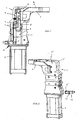
- the clamping device is made by reference to Fig.1 as before from a arranged in a tensioning head piece 1 adjusting mechanism 2 with a linearly adjustable by a drive 3, provided with position transmitter 4 and adjustable in length actuator 5, which is in communication with a clamping arm 6, wherein in the travel of the position sensor 4 at least one sensor. 7 arranged to detect at least one end position of the clamping arm 6 and equipped with elements 8 for passing the at least one end position signal.
- Fig.1 there is the guided linearly in the head piece 1 actuator 5, for example, from two mutually toothed in different positions parts T, T '. Depending on the toothing position of these parts T, T 'results in a more or less large opening angle ⁇ for the tensioning arm 6.
- T ' Results in a more or less large opening angle ⁇ for the tensioning arm 6.
- an embodiment is preferred in that the one sensor 7 and another sensor 7 'in linear distanced , Stationary assignment in the form of the already mentioned cassette 11 in the head piece 1 along the Geberstellweges inside the head piece 1 are arranged.
- the head piece 1 is formed in a known manner from two halves 1 ', 1 ", wherein the cassette 11 is arranged in one of the halves which are substantially cup-shaped, such a protected installation of the cassette also applies to the case where the head piece 1 is fork-shaped should be, which is also common in such fixtures.
- interface halves 9,9 ' are preferably in the form of inductive current and signal transformers, since in this way not only a signal transmission to the connector terminal 10 can take place, but vice versa from there also a power supply Sensors 7,7 'itself, which is a prerequisite that even query signals generated and can be passed.
- the signal transmission can also be done optically.
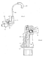
- Fig.2 referenced which shows the cassette 11 separate plug connector part 10 with its interface half 9 'in the insertion position.
- the plug connection part 10 is provided with a fastened to the outside of the head piece 1 holding extension 14.
- FIG. 6 Apart from such a mapping of the interfaces halves 9,9 'but they can also reference Figure 6 be associated under interposition of an inductive transmission element 12 operatively connected to each other, if this should require special design conditions on the device itself or their arrangement conditions at the site.
- a concrete embodiment in this respect shows the above Figure 6 according to which the inductive transmission element 12 passes through the wall 1 'of the head piece 1 and engages contactlessly with its ends projecting out of the wall 1' into the respective interface half 9, 9 'or its induction coils 15.
- the plug-side connector 10, which is not particularly shown here, which contains a coil 15, is also fastened access-accessible on the outside of the head piece 1 detachably with one or two small screws.
- the plug 90 and the plug receptacle 90' are provided outside the power supply in a suitable manner with Verrastungs instituten, the on the one hand support the cohesion of said elements, on the other hand, but easily solve each other in a side load.
- Such latching elements can be formed, for example, from at least one small, dome-like depression on one element and a small nubs can be latched therein on the other element, which is not particularly illustrated, as readily conceivable.
Abstract
Description
Die Erfindung betrifft eine Spannvorrichtung, insbesondere Kniehebelspannvorrichtung, gemäß Oberbegriff des Patentanspruches 1, die aus dem Dokument
Spannvorrichtungen der genannten Art sind hinlänglich bekannt und in Benutzung, so daß es diesbezüglich an sich keines druckschriftlichen Nachweises bedarf. Verwiesen sei jedoch bspw. auf das
Tritt ein Schadensfall an Spannvorrichtungen, und zwar insbesondere an den exponierten Steckanschlüssen auf, so muß die ganze, den Steckanschluß aufweisende Kassette ausgetauscht werden, was bedeutet, daß die relativ teuren Endstellungsabfrageelemente, egal ob Sensoren, Mikroschalter od.dgl., einer Verschrottung mit anheimfallen. Außerdem müssen in der neuen Austauschkassette gegf. die Abfrageelemente wieder entsprechend eingestellt und es muß das Anschlußkabel mit seinem Stecker wieder angeschlossen werden, was wiederum zu Beschädigungen führen kann, weil solche Spannvorrichtungen bspw. im Zuge von Fertigungsstraßen für die Fertigung von Karosserien in der Regel nur ungünstig zugänglich sind. Das Gleiche gilt auch dann, wenn ein ganzer, schadhaft gewordener Spanner ausgetauscht werden muß. Zu berücksichtigen ist dabei, daß solche Austauschvorgänge in der Regel mit einem Stop der Fertigungsvorgänge verbunden sind, das Wartungspersonal also gehalten ist, solche Austauschvorgänge in höchster Eile durchzuführen.Clamping devices of the type mentioned are well known and in use, so that in this regard, no documentary proof is required. However, reference is made, for example, to the
If an event of damage to tensioning devices, in particular on the exposed plug connections, so must whole, the plug-in connector having cassette to be replaced, which means that the relatively expensive Endstellungsabfrageelemente, whether sensors, micro-switches or the like., A scrapping with fall. In addition, in the new replacement cassette gegf. the query elements set again accordingly and it must be reconnected the connection cable with its plug, which in turn can lead to damage, because such fixtures, for example. In the course of production lines for the production of bodies in general are only unfavorably accessible. The same applies even if a whole, damaged tensioner must be replaced. It should be noted that such exchanges are usually associated with a stop of the manufacturing operations, the maintenance staff is thus held to perform such exchanges in a hurry.
Ausgehend von einer Spannvorrichtung der eingangs genannten Art, also einer solchen, die keinen Einstellungszugriff für die Endstellungssensoren braucht, liegt der Erfindung die Aufgabe zugrunde, hier Abhilfe zu schaffen, d.h., Spannvorrichtungen bzgl. ihrer Endstellungsabfrageeinrichtungen dahingehend zu verbessern und auszugestalten, daß bei unvermeidbar immer wieder auftretenden Austauscherfordernissen, diese nicht nur auf das notwendige Minimum reduziert sondern auch schnell und problemlos durchführbar sind.Starting from a clamping device of the type mentioned, so one that does not need adjustment access for the Endstellungssensoren, the invention has for its object to remedy this, ie, jigs regarding their Endstellungsabfrageeinrichtungen to improve and to design that always unavoidable re-occurring exchange requirements, these are not only reduced to the necessary minimum but can also be carried out quickly and easily.
Diese Aufgabe ist mit einer Spannvorrichtung der eingangs genannten Art nach der Erfindung durch die im Patentanspruches 1 angeführten Merkmale gelöst. Vorteilhafte Weiterbildungen ergeben sich nach den abhängigen Patentansprüchen 2 bis 10.This object is achieved with a clamping device of the type mentioned according to the invention by the features cited in
Die erfindungsgemäße Lösung nutzt also zum Einen die Gegebenheit bzw. Erkenntnis aus, daß bei Spannvorrichtungen mit längenveränderlichem Stellglied die Elemente für die Endstellungsabfrage nicht mehr zugriffszugänglich am Kopfstück installiert sein müssen, d.h., ohne weiteres vollkommen geschützt im Kopfstück plazierbar sind, und zum Anderen dadurch, daß besonders gefährdete Steckeranschlußteil bzw. die Elemente zur Signalweiterleitung von den Elementen zur Endstellungsabfrage einerseits getrennt zu halten und problemlos für Austauscherfordernisse lösbar am Kopfstück zu befestigen sind und dabei andererseits dafür zu sorgen, daß trotz Getrennthaltung eine Signalübertragung und auch Stromversorgung der Abfragelemente gewährleistet ist.Thus, the solution according to the invention makes use, on the one hand, of the fact or knowledge that, in the case of tensioning devices with a variable-length actuator, the elements for the end position query no longer have to be installed on the head end to be accessible, ie, completely protected without further ado be placed in the head piece, and on the other hand, that particularly vulnerable male connector part or the elements for signal forwarding from the elements for Endstellungsabfrage one hand to keep separate and easily removable for Austauscherfordernisse to attach the head and on the other hand to ensure that despite a separate holding a Signal transmission and power supply of the interrogator is guaranteed.
Eine Besonderheit besteht insofern, als einerseits die kontaktlose Energieübertragung via Schnittstelle für zwei bis drei Sensoren ausreichend ist, es aber andererseits Spannvorrichtungen gibt, bei denen eine kontinuierliche und höhere Energie verlangende Wegemessung erfolgt. Eine solche höhere Energieübertragung ist aber, soweit bekannt, mit den bisher verfügbaren Mitteln nicht möglich. Da aber insoweit die gleiche Gefährdungsproblematik auch für solche Spannvorrichtungen besteht, ist diese auf die gleiche erfindungsgemäße Weise zu lösen, dies allerdings mit dem Unterschied, daß die Schnittstellenhälften als Stecker und Steckeraufnahme ausgebildet sind, wobei die Einsteckkontakte des Steckers bei dessen Seitenbelastung leicht trennbar bzgl. ihrer Einstecklänge kurz bemessen sind.A special feature is that on the one hand, the contactless energy transmission via interface for two to three sensors is sufficient, but on the other hand there are tensioning devices in which a continuous and higher energy-demanding path measurement takes place. However, such a higher energy transfer is, as far as known, not possible with the resources available so far. However, since the extent to which the same hazard problem also exists for such tensioning devices, this is to be solved in the same manner according to the invention, but with the difference that the interface halves are designed as a plug and plug receptacle, the plug-in contacts of the plug with its side load easily separable respect. their insertion length are short.
Die erfindungsgemäße Spannvorrichtung einschließlich vorteilhafter Weiterbildungen gemäß der abhängigen Patentansprüche wird nachfolgend anhand der zeichnerischen Darstellung von Ausführungsbeispielen näher erläutert.The clamping device according to the invention including advantageous developments according to the dependent claims will be explained in more detail with reference to the drawing of exemplary embodiments.
Es zeigt
- Fig.1
- schematisch eine Spannvorrichtung, in Seitenansicht mit geöffnetem Kopfstück;
- Fig.2
- perspektivisch die Spannvorrichtung mit dem einschiebbar zuzuordnenden Steckeranschlußteil;
- Fig.3
- vergrößert und perspektivisch das Steckeranschlußteil;
- Fig.4
- perspektivisch eine Endstellungsabfragekassette;
- Fig.5
- perspektivisch die Zuordnung von Endstellungsabfragekassette und Steckeranschßteil;
- Fig.6
- im Schnitt eine besondere Ausführungs- und Anordnungsform der Schnittstelle am Kopfstück;
- Fig.7
- perspektivisch das Ausführungsbeispiel eines Sensoranschlusses für eine kontinuierliche Wegemessung und
- Fig.8
- in Seitenansicht den Sensoranschluß gemäß
Fig.7 im Kopfstück einer Spannvorrichtung.
- Fig.1
- schematically a clamping device, in side view with opened head piece;
- Fig.2
- in perspective, the clamping device with the plug-in connector part to be inserted in an insertable manner;
- Figure 3
- enlarged and perspective the plug connector part;
- Figure 4
- in perspective, an end position sensing cartridge;
- Figure 5
- in perspective, the assignment of Endstellungsabfragekassette and Steckeranschßteil;
- Figure 6
- on average, a particular embodiment and arrangement of the interface on the head piece;
- Figure 7
- in perspective, the embodiment of a sensor terminal for a continuous path measurement and
- Figure 8
- in side view the sensor connection according to
Figure 7 in the head piece of a clamping device.
Die Spannvorrichtung besteht unter Verweis auf
Wie aus
Für eine solche Spannvorrichtung ist nun wesentlich, daß der mindestens eine Sensor 7 und die Elemente 8 zur Weitergabe des mindestens einen Endstellungssignales am bzw. im Kopfstück 1 als separate Ein- und Anbauteile angeordnet, mit je einer Schnittstellenhälfte 9,9' versehen und dabei im Kopfstück 1 derart einander zugeordnet sind, daß die Schnittstellenhälften 9,9' für eine kontaktlose Übertragung des mindestens einen Endstellungssignales in Wirkverbindung stehen, wobei die Elemente 8 zur Signalweitergabe mit einem Steckeranschlußteil 10 zugriffszugänglich am Kopfstück 1 angeordnet und an diesem lösbar befestigt sind.For such a clamping device is now essential that the at least one
Verwiesen wird hierzu ebenfalls auf
Da für die Endstellungsabfragesensoren 7 kein Einstellungs- bzw. Zugriffserfordernis mehr besteht und in der Regel Abfragen für die Schließ- und Öffnungsstellung des Spannarmes 6 gefordert sind, wird eine Ausführungsform dahingehend bevorzugt, daß der eine Sensor 7 und ein weiterer Sensor 7' in linear distanzierter, stationärer Zuordnung in Form der bereits vorerwähnten Kassette 11 im Kopfstück 1 längs des Geberstellweges im Inneren des Kopfstückes 1 angeordnet sind. Diesbezüglich und unter Verweis auf
Was die hier sogenannten Schnittstellenhälften 9,9' betrifft, so sind diese bevorzugt in Form induktiver Strom- und Signalübertrager ausgebildet, da auf diese Weise nicht nur eine Signalübertragung an den Steckeranschluß 10 erfolgen kann, sondern umgekehrt von da aus auch eine Stromversorgung der Sensoren 7,7' selbst, die ja Voraussetzung dafür ist, daß überhaupt Abfragesignale erzeugt und weitergegeben werden können. Die Signalübertragung kann dabei auch auf optischem Wege erfolgen.As regards the so-called
Ferner sind die Schnittstellenhälften 9,9' in lappenartigen Fortsätzen 13,13' der Kassette 11 und des Steckeranschlußteiles 10 untergebracht, wobei der Fortsatz 13' des Steckeranschlußteiles 10 am Kopfstück 1 fluchtend zum Fortsatz 13 der im Kopfstück 1 befindlichen Kassette 11 in das Kopfstück 1 einschiebbar ausgebildet ist. Hierzu wird auf
Abgesehen von einer solchen Zuordnung der Schnittstellen hälften 9,9' können diese aber auch unter Verweis auf
Bezgl. der einleitend erwähnten Besonderheit, gemäß der die Schnittstellenhälften 9,9' als Stecker 90 und Steckeraufnahme 90' ausgebildet und die Einsteckkontakte 91 des Steckers 90 bei dessen Seitenbelastung leicht trennbar bzgl. ihrer Einstecklänge L kurz bemessen sind, wird auf die
Der die Weglänge beim Ausführungsbeispiel nach
The path length in the embodiment according to
Abgesehen von der zu
- 11
- SpannerkopfstückSpanner head
- 1', 1"1 ', 1 "
- KopfstückhälftenHead halves
- 22
- Stellmechanikactuating mechanism
- 33
- Antriebdrive
- 44
- Stellungsgeberposition transmitter
- 55
- Stellgliedactuator
- 66
- Spannarmclamping arm
- 7,7'7,7 '
- Sensorsensor
- 88th
- Elementeelements
- 9, 9'9, 9 '
- SchnittstellenhälftenInterface halves
- 1010
- SteckeranschlußteilMale fitting part
- 1111
- Kassettecassette
- 1212
- Übertragungselementtransmission element
- 1-3,13'1 to 3.13 '
- Fortsätzeprojections
- 1414
- HaltefortsatzHolding projection
- 1515
- Induktionsspuleninductors
- T,T'T, T '
- StellgliedteileActuator parts
- 9090
- Steckerplug
- 90'90 '
- Steckeraufnahmeplug receptacle
- 9191
- Einsteckkontakteinsert contacts
- LL
- EinstecklängeInsertion
- 9292
- Stellwelleactuating shaft
- 9393
- Sensorsensor
- 9494
- Leitungmanagement
Claims (10)
- A clamping device, in particular a toggle clamping device, consisting of an adjusting mechanism (2) arranged in a clamp headpiece (1) comprising an adjustable-length control member (5) which is linearly adjustable by means of a drive (3) and is provided with position sensors (4), which control member is connected to a clamping arm (6), wherein at least one sensor (7) for detecting at least one end position of the clamping arm (6) is arranged in the adjusting path of the position sensor (4) and is equipped with elements (8) for transmitting the at least one end position signal,
characterised in
that the at least one sensor (7) and the elements (8) for transmitting the at least one end position signal are arranged on or in the headpiece (1) as separate built-in and attachment parts, are each provided with an interface half (9, 9') and thereby assigned to one another in the head piece (1) in such a manner that the interface halves (9, 9') are operatively connected for contactless transmission of the at least one end position signal, wherein the elements (8) for transmission of the at least one end position signal with a plug connecting part (10) are arranged on the headpiece (1) so that they are accessible for access and are detachably connected thereto. - The clamping device according to claim 1,
characterised in
that the one sensor (7) and a further sensor (7') are arranged in a linearly distanced, stationary arrangement in the form of a cassette (11) along the path of the position sensor in the interior of the headpiece (1). - The clamping device according to claim 2,
characterised in
that the headpiece (1) is formed from two halves (1', 1") and the cassette (11) is arranged in one of the halves. - The clamping device according to any one of claims 1 to 3,
characterised in
that the interface halves (9, 9') are configured in the form of inductive current and signal transmitters. - The clamping device according to claim 4,
characterised in
that the interface halves (9, 9') are assigned in operative connection to one another with an interposed inductive transmission element (12). - The clamping device according to claim 5,
characterised in
that the inductive transmission element (12) passes through the wall (1') of the headpiece (1) and with its ends projecting from the wall (1') engages in a contactless manner in the respective interface halves (9, 9'). - The clamping device according to any one of claims 2 to 4,
characterised in
that the interface halves (9, 9') are arranged in lobe-like continuations (13, 13') of the cassette (11) and the plug connection part (10), wherein the continuation (13) of the plug connection part (10) on the headpiece (1) in alignment with the continuation (13') of the cassette (11) is configured as insertable into the headpiece. - The clamping device according to claim 7,
characterised in
that the plug connection part (10) is provided with a retaining continuation (14) which can be fastened externally on the headpiece (1). - The clamping device according to any one of claims 1 to 8 with a sensor (7') for continuous distance measurement, which requires a higher energy transmission,
characterised in
that the interface halves (9, 9') are configured as plug (90) and plug receptacle (90'), wherein the plug-in contacts (91) of the plug (90) are designed to be short with regard to their plug-in length (L) having a length of 3 to 5 mm for easy separation of the contacts. - The clamping device according to claim 9,
characterised in
that outside the current passages, the plug (90) and the plug receptacle (90') are additionally provided with locking elements which additionally support their cohesion but are easily detachable.
Applications Claiming Priority (2)
| Application Number | Priority Date | Filing Date | Title |
|---|---|---|---|
| DE10256385A DE10256385B3 (en) | 2002-12-02 | 2002-12-02 | Elbow lever clamp has sensor for final position and elements for forwarding final position signal mounted as separate components in head piece with interactive interfaces for contactless transfer of signal |
| DE10256385 | 2002-12-02 |
Publications (3)
| Publication Number | Publication Date |
|---|---|
| EP1426143A2 EP1426143A2 (en) | 2004-06-09 |
| EP1426143A3 EP1426143A3 (en) | 2007-08-15 |
| EP1426143B1 true EP1426143B1 (en) | 2009-04-15 |
Family
ID=30775619
Family Applications (1)
| Application Number | Title | Priority Date | Filing Date |
|---|---|---|---|
| EP03018177A Expired - Lifetime EP1426143B1 (en) | 2002-12-02 | 2003-08-09 | Clamping device, especially toggle lever clamp |
Country Status (5)
| Country | Link |
|---|---|
| EP (1) | EP1426143B1 (en) |
| AT (1) | ATE428540T1 (en) |
| DE (2) | DE10256385B3 (en) |
| ES (1) | ES2321592T3 (en) |
| PT (1) | PT1426143E (en) |
Cited By (1)
| Publication number | Priority date | Publication date | Assignee | Title |
|---|---|---|---|---|
| CN105313040A (en) * | 2014-08-01 | 2016-02-10 | 佩佩尔+富克斯有限公司 | Query unit for toggle lever clamp |
Families Citing this family (7)
| Publication number | Priority date | Publication date | Assignee | Title |
|---|---|---|---|---|
| ITMI20061226A1 (en) * | 2006-06-26 | 2007-12-27 | Univer Spa | DEVICE FOR LOCKING AND-OR WORKING OF PIECES TO WORK WITH OPERATING POSITIONS SET TO MANUALLY |
| DE102009054153A1 (en) | 2009-11-23 | 2011-05-26 | De-Sta-Co Europe Gmbh | jig |
| EP2433750B1 (en) | 2010-09-23 | 2013-04-10 | DE-STA-CO Europe GmbH | Actuation device |
| DE102010046188A1 (en) | 2010-09-23 | 2012-03-29 | De-Sta-Co Europe Gmbh | actuator |
| DE102011107397A1 (en) | 2011-07-07 | 2013-01-10 | De-Sta-Co Europe Gmbh | actuator |
| DE102013001004B3 (en) * | 2013-01-22 | 2014-02-06 | Tünkers Maschinenbau Gmbh | Device useful for e.g. clamping, stamping, welding of components used in the car body of motor vehicle industry, comprises elongated adjusting part, sensor device with electrical or inductive sensors or micro-switches and control device |
| FR3027387B1 (en) | 2014-10-16 | 2018-02-16 | Senstronic | SENSOR DEVICE WITH MODULAR CONSTITUTION AND INDUSTRIAL EQUIPMENT COMPRISING SAME |
Family Cites Families (3)
| Publication number | Priority date | Publication date | Assignee | Title |
|---|---|---|---|---|
| DE29718644U1 (en) * | 1997-10-21 | 1997-12-11 | Tuenkers Maschinenbau Gmbh | Query cassette |
| DE20004977U1 (en) * | 2000-03-17 | 2000-07-13 | Festo Ag & Co | Headpiece of a tensioning device |
| DE20209237U1 (en) * | 2002-06-13 | 2002-09-19 | Sta Co Mettallerzeugnisse Gmbh | Toggle clamp |
-
2002
- 2002-12-02 DE DE10256385A patent/DE10256385B3/en not_active Expired - Fee Related
-
2003
- 2003-08-09 PT PT03018177T patent/PT1426143E/en unknown
- 2003-08-09 AT AT03018177T patent/ATE428540T1/en not_active IP Right Cessation
- 2003-08-09 ES ES03018177T patent/ES2321592T3/en not_active Expired - Lifetime
- 2003-08-09 EP EP03018177A patent/EP1426143B1/en not_active Expired - Lifetime
- 2003-08-09 DE DE50311413T patent/DE50311413D1/en not_active Expired - Lifetime
Cited By (2)
| Publication number | Priority date | Publication date | Assignee | Title |
|---|---|---|---|---|
| CN105313040A (en) * | 2014-08-01 | 2016-02-10 | 佩佩尔+富克斯有限公司 | Query unit for toggle lever clamp |
| US10710205B2 (en) | 2014-08-01 | 2020-07-14 | Pepperl+Fuchs Gmbh | Query unit for toggle lever clamp |
Also Published As
| Publication number | Publication date |
|---|---|
| DE10256385B3 (en) | 2004-02-26 |
| PT1426143E (en) | 2009-06-04 |
| ATE428540T1 (en) | 2009-05-15 |
| EP1426143A3 (en) | 2007-08-15 |
| ES2321592T3 (en) | 2009-06-09 |
| EP1426143A2 (en) | 2004-06-09 |
| DE50311413D1 (en) | 2009-05-28 |
Similar Documents
| Publication | Publication Date | Title |
|---|---|---|
| EP0226532B1 (en) | Electrical switching cubicle with a racking drive for a movable switching apparatus | |
| EP1862767B1 (en) | Safety positioning sensor for cylinder, cylinders with such a positioning sensor | |
| EP0616236A1 (en) | Connector for a lightguide | |
| DE3917242A1 (en) | SOLENOID VALVE BATTERY | |
| EP1426143B1 (en) | Clamping device, especially toggle lever clamp | |
| EP3763882A1 (en) | Quick change device | |
| EP0292743B1 (en) | Door closer with a closing force indicating device | |
| EP1702409A1 (en) | Safety switch for monitoring a closing position of two parts which can be displaced in relation to each other | |
| EP1921242A1 (en) | Actuation device for moveable building parts, in particular pivotable windows or doors | |
| EP0439063A2 (en) | Clamping device | |
| DE102007020313B4 (en) | Device for monitoring the state of a protective device of a machine | |
| EP0359073A2 (en) | Clamping device | |
| EP1351041B1 (en) | Wind protection for a balance | |
| EP0180146A2 (en) | Punching machine | |
| DE102008046179A1 (en) | Optoelectronic sensor and method of attachment | |
| DE102016108612A1 (en) | Stud Welding Gun | |
| DE4318125B4 (en) | Hollow body for electrical installation | |
| DE19917211C1 (en) | Device for switching a connection depending on the state of a device to be monitored, in particular a safety switch | |
| DE202006006864U1 (en) | Device for locking a sliding door | |
| DE102007027191B4 (en) | Fastening element and holding element and device for holding a control element | |
| DE102005005450A1 (en) | Switchgear cabinet lock, has locking unit with electrically controlled pin that is moved in and out of recess by lift magnets that are operated by access control system, to which pin is connected, when authorized transponder is near handle | |
| DE10210635B4 (en) | Explosion-proof housing with modular attachment housing | |
| DE3406410A1 (en) | Hydraulic door closer with opening-angle signalling | |
| WO2001077473A1 (en) | Device for monitoring the position of a door leaf | |
| DE202010015812U1 (en) | Adhesive magnetic device |
Legal Events
| Date | Code | Title | Description |
|---|---|---|---|
| PUAI | Public reference made under article 153(3) epc to a published international application that has entered the european phase |
Free format text: ORIGINAL CODE: 0009012 |
|
| AK | Designated contracting states |
Kind code of ref document: A2 Designated state(s): AT BE BG CH CY CZ DE DK EE ES FI FR GB GR HU IE IT LI LU MC NL PT RO SE SI SK TR |
|
| AX | Request for extension of the european patent |
Extension state: AL LT LV MK |
|
| RAP1 | Party data changed (applicant data changed or rights of an application transferred) |
Owner name: DE-STA-CO EUROPE GMBH |
|
| PUAL | Search report despatched |
Free format text: ORIGINAL CODE: 0009013 |
|
| AK | Designated contracting states |
Kind code of ref document: A3 Designated state(s): AT BE BG CH CY CZ DE DK EE ES FI FR GB GR HU IE IT LI LU MC NL PT RO SE SI SK TR |
|
| AX | Request for extension of the european patent |
Extension state: AL LT LV MK |
|
| 17P | Request for examination filed |
Effective date: 20071205 |
|
| AKX | Designation fees paid |
Designated state(s): AT BE BG CH CY CZ DE DK EE ES FI FR GB GR HU IE IT LI LU MC NL PT RO SE SI SK TR |
|
| GRAP | Despatch of communication of intention to grant a patent |
Free format text: ORIGINAL CODE: EPIDOSNIGR1 |
|
| GRAS | Grant fee paid |
Free format text: ORIGINAL CODE: EPIDOSNIGR3 |
|
| GRAA | (expected) grant |
Free format text: ORIGINAL CODE: 0009210 |
|
| AK | Designated contracting states |
Kind code of ref document: B1 Designated state(s): AT BE BG CH CY CZ DE DK EE ES FI FR GB GR HU IE IT LI LU MC NL PT RO SE SI SK TR |
|
| REG | Reference to a national code |
Ref country code: CH Ref legal event code: EP Ref country code: GB Ref legal event code: FG4D Free format text: NOT ENGLISH |
|
| REG | Reference to a national code |
Ref country code: IE Ref legal event code: FG4D |
|
| REF | Corresponds to: |
Ref document number: 50311413 Country of ref document: DE Date of ref document: 20090528 Kind code of ref document: P |
|
| REG | Reference to a national code |
Ref country code: PT Ref legal event code: SC4A Free format text: AVAILABILITY OF NATIONAL TRANSLATION Effective date: 20090528 |
|
| REG | Reference to a national code |
Ref country code: ES Ref legal event code: FG2A Ref document number: 2321592 Country of ref document: ES Kind code of ref document: T3 |
|
| REG | Reference to a national code |
Ref country code: SE Ref legal event code: TRGR |
|
| NLV1 | Nl: lapsed or annulled due to failure to fulfill the requirements of art. 29p and 29m of the patents act | ||
| PG25 | Lapsed in a contracting state [announced via postgrant information from national office to epo] |
Ref country code: NL Free format text: LAPSE BECAUSE OF FAILURE TO SUBMIT A TRANSLATION OF THE DESCRIPTION OR TO PAY THE FEE WITHIN THE PRESCRIBED TIME-LIMIT Effective date: 20090415 Ref country code: SI Free format text: LAPSE BECAUSE OF FAILURE TO SUBMIT A TRANSLATION OF THE DESCRIPTION OR TO PAY THE FEE WITHIN THE PRESCRIBED TIME-LIMIT Effective date: 20090415 |
|
| REG | Reference to a national code |
Ref country code: IE Ref legal event code: FD4D |
|
| PG25 | Lapsed in a contracting state [announced via postgrant information from national office to epo] |
Ref country code: DK Free format text: LAPSE BECAUSE OF FAILURE TO SUBMIT A TRANSLATION OF THE DESCRIPTION OR TO PAY THE FEE WITHIN THE PRESCRIBED TIME-LIMIT Effective date: 20090415 Ref country code: RO Free format text: LAPSE BECAUSE OF FAILURE TO SUBMIT A TRANSLATION OF THE DESCRIPTION OR TO PAY THE FEE WITHIN THE PRESCRIBED TIME-LIMIT Effective date: 20090415 Ref country code: EE Free format text: LAPSE BECAUSE OF FAILURE TO SUBMIT A TRANSLATION OF THE DESCRIPTION OR TO PAY THE FEE WITHIN THE PRESCRIBED TIME-LIMIT Effective date: 20090415 Ref country code: IE Free format text: LAPSE BECAUSE OF FAILURE TO SUBMIT A TRANSLATION OF THE DESCRIPTION OR TO PAY THE FEE WITHIN THE PRESCRIBED TIME-LIMIT Effective date: 20090415 |
|
| PLBE | No opposition filed within time limit |
Free format text: ORIGINAL CODE: 0009261 |
|
| STAA | Information on the status of an ep patent application or granted ep patent |
Free format text: STATUS: NO OPPOSITION FILED WITHIN TIME LIMIT |
|
| PG25 | Lapsed in a contracting state [announced via postgrant information from national office to epo] |
Ref country code: SK Free format text: LAPSE BECAUSE OF FAILURE TO SUBMIT A TRANSLATION OF THE DESCRIPTION OR TO PAY THE FEE WITHIN THE PRESCRIBED TIME-LIMIT Effective date: 20090415 |
|
| 26N | No opposition filed |
Effective date: 20100118 |
|
| PG25 | Lapsed in a contracting state [announced via postgrant information from national office to epo] |
Ref country code: BG Free format text: LAPSE BECAUSE OF FAILURE TO SUBMIT A TRANSLATION OF THE DESCRIPTION OR TO PAY THE FEE WITHIN THE PRESCRIBED TIME-LIMIT Effective date: 20090715 Ref country code: MC Free format text: LAPSE BECAUSE OF NON-PAYMENT OF DUE FEES Effective date: 20090831 |
|
| REG | Reference to a national code |
Ref country code: CH Ref legal event code: PL |
|
| PG25 | Lapsed in a contracting state [announced via postgrant information from national office to epo] |
Ref country code: CH Free format text: LAPSE BECAUSE OF NON-PAYMENT OF DUE FEES Effective date: 20090831 Ref country code: LI Free format text: LAPSE BECAUSE OF NON-PAYMENT OF DUE FEES Effective date: 20090831 |
|
| PG25 | Lapsed in a contracting state [announced via postgrant information from national office to epo] |
Ref country code: GR Free format text: LAPSE BECAUSE OF FAILURE TO SUBMIT A TRANSLATION OF THE DESCRIPTION OR TO PAY THE FEE WITHIN THE PRESCRIBED TIME-LIMIT Effective date: 20090716 |
|
| PG25 | Lapsed in a contracting state [announced via postgrant information from national office to epo] |
Ref country code: AT Free format text: LAPSE BECAUSE OF NON-PAYMENT OF DUE FEES Effective date: 20090809 |
|
| PG25 | Lapsed in a contracting state [announced via postgrant information from national office to epo] |
Ref country code: IT Free format text: LAPSE BECAUSE OF FAILURE TO SUBMIT A TRANSLATION OF THE DESCRIPTION OR TO PAY THE FEE WITHIN THE PRESCRIBED TIME-LIMIT Effective date: 20090415 |
|
| PG25 | Lapsed in a contracting state [announced via postgrant information from national office to epo] |
Ref country code: LU Free format text: LAPSE BECAUSE OF NON-PAYMENT OF DUE FEES Effective date: 20090809 |
|
| PG25 | Lapsed in a contracting state [announced via postgrant information from national office to epo] |
Ref country code: HU Free format text: LAPSE BECAUSE OF FAILURE TO SUBMIT A TRANSLATION OF THE DESCRIPTION OR TO PAY THE FEE WITHIN THE PRESCRIBED TIME-LIMIT Effective date: 20091016 |
|
| PG25 | Lapsed in a contracting state [announced via postgrant information from national office to epo] |
Ref country code: TR Free format text: LAPSE BECAUSE OF FAILURE TO SUBMIT A TRANSLATION OF THE DESCRIPTION OR TO PAY THE FEE WITHIN THE PRESCRIBED TIME-LIMIT Effective date: 20090415 |
|
| PG25 | Lapsed in a contracting state [announced via postgrant information from national office to epo] |
Ref country code: CY Free format text: LAPSE BECAUSE OF FAILURE TO SUBMIT A TRANSLATION OF THE DESCRIPTION OR TO PAY THE FEE WITHIN THE PRESCRIBED TIME-LIMIT Effective date: 20090415 |
|
| REG | Reference to a national code |
Ref country code: FR Ref legal event code: PLFP Year of fee payment: 13 |
|
| PGFP | Annual fee paid to national office [announced via postgrant information from national office to epo] |
Ref country code: FI Payment date: 20150819 Year of fee payment: 13 Ref country code: CZ Payment date: 20150805 Year of fee payment: 13 Ref country code: ES Payment date: 20150720 Year of fee payment: 13 Ref country code: GB Payment date: 20150818 Year of fee payment: 13 Ref country code: PT Payment date: 20150717 Year of fee payment: 13 Ref country code: DE Payment date: 20150717 Year of fee payment: 13 |
|
| PGFP | Annual fee paid to national office [announced via postgrant information from national office to epo] |
Ref country code: FR Payment date: 20150831 Year of fee payment: 13 Ref country code: SE Payment date: 20150818 Year of fee payment: 13 Ref country code: BE Payment date: 20150728 Year of fee payment: 13 |
|
| PG25 | Lapsed in a contracting state [announced via postgrant information from national office to epo] |
Ref country code: BE Free format text: LAPSE BECAUSE OF NON-PAYMENT OF DUE FEES Effective date: 20160831 |
|
| REG | Reference to a national code |
Ref country code: DE Ref legal event code: R119 Ref document number: 50311413 Country of ref document: DE |
|
| REG | Reference to a national code |
Ref country code: SE Ref legal event code: EUG |
|
| GBPC | Gb: european patent ceased through non-payment of renewal fee |
Effective date: 20160809 |
|
| PG25 | Lapsed in a contracting state [announced via postgrant information from national office to epo] |
Ref country code: SE Free format text: LAPSE BECAUSE OF NON-PAYMENT OF DUE FEES Effective date: 20160810 Ref country code: FI Free format text: LAPSE BECAUSE OF NON-PAYMENT OF DUE FEES Effective date: 20160809 |
|
| REG | Reference to a national code |
Ref country code: FR Ref legal event code: ST Effective date: 20170428 |
|
| PG25 | Lapsed in a contracting state [announced via postgrant information from national office to epo] |
Ref country code: PT Free format text: LAPSE BECAUSE OF NON-PAYMENT OF DUE FEES Effective date: 20170209 Ref country code: CZ Free format text: LAPSE BECAUSE OF NON-PAYMENT OF DUE FEES Effective date: 20160809 |
|
| PG25 | Lapsed in a contracting state [announced via postgrant information from national office to epo] |
Ref country code: FR Free format text: LAPSE BECAUSE OF NON-PAYMENT OF DUE FEES Effective date: 20160831 Ref country code: GB Free format text: LAPSE BECAUSE OF NON-PAYMENT OF DUE FEES Effective date: 20160809 Ref country code: DE Free format text: LAPSE BECAUSE OF NON-PAYMENT OF DUE FEES Effective date: 20170301 |
|
| REG | Reference to a national code |
Ref country code: ES Ref legal event code: FD2A Effective date: 20180507 |
|
| PG25 | Lapsed in a contracting state [announced via postgrant information from national office to epo] |
Ref country code: ES Free format text: LAPSE BECAUSE OF NON-PAYMENT OF DUE FEES Effective date: 20160810 |