EP1424795B1 - Système de transmission optique utilisant un modulateur de phase optique - Google Patents
Système de transmission optique utilisant un modulateur de phase optique Download PDFInfo
- Publication number
- EP1424795B1 EP1424795B1 EP03015980A EP03015980A EP1424795B1 EP 1424795 B1 EP1424795 B1 EP 1424795B1 EP 03015980 A EP03015980 A EP 03015980A EP 03015980 A EP03015980 A EP 03015980A EP 1424795 B1 EP1424795 B1 EP 1424795B1
- Authority
- EP
- European Patent Office
- Prior art keywords
- optical
- signal
- duobinary
- transmission system
- phase
- Prior art date
- Legal status (The legal status is an assumption and is not a legal conclusion. Google has not performed a legal analysis and makes no representation as to the accuracy of the status listed.)
- Expired - Fee Related
Links
Images


Classifications
-
- H—ELECTRICITY
- H04—ELECTRIC COMMUNICATION TECHNIQUE
- H04B—TRANSMISSION
- H04B10/00—Transmission systems employing electromagnetic waves other than radio-waves, e.g. infrared, visible or ultraviolet light, or employing corpuscular radiation, e.g. quantum communication
- H04B10/50—Transmitters
-
- H—ELECTRICITY
- H04—ELECTRIC COMMUNICATION TECHNIQUE
- H04B—TRANSMISSION
- H04B10/00—Transmission systems employing electromagnetic waves other than radio-waves, e.g. infrared, visible or ultraviolet light, or employing corpuscular radiation, e.g. quantum communication
- H04B10/50—Transmitters
- H04B10/501—Structural aspects
- H04B10/503—Laser transmitters
- H04B10/505—Laser transmitters using external modulation
- H04B10/5051—Laser transmitters using external modulation using a series, i.e. cascade, combination of modulators
-
- H—ELECTRICITY
- H04—ELECTRIC COMMUNICATION TECHNIQUE
- H04B—TRANSMISSION
- H04B10/00—Transmission systems employing electromagnetic waves other than radio-waves, e.g. infrared, visible or ultraviolet light, or employing corpuscular radiation, e.g. quantum communication
- H04B10/50—Transmitters
- H04B10/501—Structural aspects
- H04B10/503—Laser transmitters
- H04B10/505—Laser transmitters using external modulation
- H04B10/5055—Laser transmitters using external modulation using a pre-coder
-
- H—ELECTRICITY
- H04—ELECTRIC COMMUNICATION TECHNIQUE
- H04B—TRANSMISSION
- H04B10/00—Transmission systems employing electromagnetic waves other than radio-waves, e.g. infrared, visible or ultraviolet light, or employing corpuscular radiation, e.g. quantum communication
- H04B10/50—Transmitters
- H04B10/516—Details of coding or modulation
- H04B10/5167—Duo-binary; Alternative mark inversion; Phase shaped binary transmission
-
- H—ELECTRICITY
- H04—ELECTRIC COMMUNICATION TECHNIQUE
- H04B—TRANSMISSION
- H04B10/00—Transmission systems employing electromagnetic waves other than radio-waves, e.g. infrared, visible or ultraviolet light, or employing corpuscular radiation, e.g. quantum communication
- H04B10/50—Transmitters
- H04B10/516—Details of coding or modulation
- H04B10/548—Phase or frequency modulation
-
- H—ELECTRICITY
- H04—ELECTRIC COMMUNICATION TECHNIQUE
- H04B—TRANSMISSION
- H04B10/00—Transmission systems employing electromagnetic waves other than radio-waves, e.g. infrared, visible or ultraviolet light, or employing corpuscular radiation, e.g. quantum communication
- H04B10/50—Transmitters
- H04B10/58—Compensation for non-linear transmitter output
Definitions
- the present invention relates to an optical transmission system, and more particularly to an optical transmission system that can improve the transmission quality and provide a high-speed transmission using an optical phase modulator.
- a DWDM (Dense-Wavelength-Division-Multiplexing) optical transmission system has an excellent communication efficiency as it can transmit an optical signal having multiple channels with different wavelengths through a single optical fiber.
- the DWDM system is capable of transmitting optical signals regardless of the transmission speed thereof.
- the DWDM systems have been widely utilized in ultra-high speed internet networks.
- a rapid increase in the data traffic and a demand for faster data transmission of more than 40 Gbps tend to cause severe interference and distortion between the channels (i.e., a channel interval less than 50GHz) when the light intensity is modulated using the conventional non-return-to-zero (NRZ) method, thereby imposing a restriction in the enlargement of transmission capacity.
- NRZ non-return-to-zero
- the transmission distance is restricted especially in the high-speed transmission of more than 10 Gbps as a direct current (DC) frequency component of the conventional binary NRZ transmission signal and a high frequency component spread, which occurs during the modulation process, cause non-linearity and dispersion when the transmission of the binary NRZ signal propagates in an optical fiber medium.
- DC direct current
- an optical duobinary transmission technology that can improve the bit spectral efficiency has been introduced as a means to enable an effective use of the limited optical fiber bandwidth.
- An advantage of the duobinary transmission is that the transmission spectrum is reduced greatly in comparison to the general binary transmission.
- FIG 1 is a block diagram showing the construction of a conventional duobinary carrier suppressed, Return-to-Zero (hereinafter, referred to as "DCS-RZ") generating transmitter.
- the conventional DCS-RZ generating transmitter includes a carrier suppressed RZ unit 10 and a duobinary modulation unit 20.
- a clock 12 applies a clock signal having a cycle of 2T to an input of a chirp-free interferometer type optical-intensity-modulator 11 to generate a carrier suppressed RZ signal.
- NRZ data are converted to a 3-level electrical signal by a duobinary precoder 21 and an electrical low pass filter 22.
- the 3-level electrical signal is amplified by a modulator driver amplifier 23 and then used to drive a chirp-free Mach-Zehnder modulator 24.
- the Mach-Zehnder interferometer type light-intensity-modulators as described above can be classified into two types: a Z-cut structure and an X-cut structure according their arm structures.
- the Z-cut structured Mach-Zehnder interferometer type light-intensity-modulator has dual arms and is driven when 3-level signals are applied through the dual arms, where as the X-cut structured Mach-Zehnder interferometer type light-intensity-modulator has a single arm and is driven when a 3-level signal is applied through the single arm.
- FIG. 1 shows a Z-cut structured Mach-Zehnder interferometer type light-intensity-modulator having dual arms, each having an electrical low pass filter 22 or 26 and a modulator driving amplifier 23 or 25, so that the 3-level electric signal can be applied to each arm.
- FIG. 2 shows an X-cut structured Mach-Zehnder interferometer type light-intensity-modulator having a single arm, which includes an electrical low pass filter 22 and a modulator driving amplifier 23, so that the 3-level electric signal can be applied to the single arm.
- FIG. 3A is a graph showing the output signals of the light-intensity-modulators of FIGs. 1 and 2
- FIG 3B is a graph showing the spectral characteristics of the output signals.
- the spectrum of the modulated signals shows the frequency components of modulated signals placed at two locations only, which are upper and lower sides of the carrier frequency without any frequency component of the carrier itself.
- Patent application EP 1 411 656 published on 21.04.2004 claiming the priority date of 16.10.2002, discloses an optical duobinary carrier-suppressed RZ transmission system, which differs from the main embodiment of the present invention in that a Mach-Zehnder optical intensity modulator is used in the duobinary signal generator of said document.
- the present invention has been made to solve the above-mentioned problems occurring in the prior art and provides additional advantages, by providing an optical transmission system using an optical phase modulator, which employs a duobinary technique using a phase modulator, so as to overcome the dependency of the transmission quality on the filtering characteristic and the bit pattern as in the conventional duobinary transmission system, thereby improving the non-linearity and dispersion characteristics of the NRZ transmission of more than 10 Gbps.
- the present invention relates to a carrier suppressed RZ (Return-to-Zero) generating transmitter capable of generating DCS-RZ, by utilizing a new duobinary optical transmission technique that can be employed in a DWDM optical transmission system.
- RZ Return-to-Zero
- the invention concerns an optical transmission system according to claim 1.
- FIG. 4 is a block diagram showing the construction of an optical transmission system employing an optical phase modulator according to an embodiment of the present invention.
- the optical transmission system employing an optical phase modulator according to the embodiment of the present invention includes a duobinary modulating section 100 for generating a duobinary signal and a carrier suppressed RZ section 200 for generating a carrier suppressed RZ.
- the duobinary modulating section 100 and the carrier suppressed RZ section 200 exhibit the same characteristics even when their positions are interchanged.
- NRZ data are encoded by a duobinary precoder 101, and the encoded signal is amplified by a driving amplifier 102 and then phase-modulated by a phase modulator 103.
- the phase modulator 103 can adjust a degree of the phase modulation by adjusting the modulation index, which indicates the degree of phase modulation.
- the optical signal whose phase has been modulated in the optical phase modulator 103 passes through an optical band pass filter 104 having a bit rate of 0.7/T.
- the optical signal is modulated into a duobinary signal while passing through the optical band pass filter 104, which is then outputted.
- the optical band pass filter 104 filters the optical signal while adjusting the bandwidth of the signal frequency within a range, which allows the signal to be transmitted without distortion.
- the modulated duobinary optical signal is incident to the chirp-free Mach-Zehnder modulator 201 of the carrier suppressed RZ section 200, and a clock signal 202 having a cycle of 2T is applied to the chirp-free Mach-Zehnder modulator 201, so as to generate a carrier suppressed RZ signal.
- FIGs. 5A and 5B are graphs illustrating the output characteristics of an optical transmission system using an optical phase modulator according to the embodiment of the present invention.
- FIG 5A shows an optical power (mW) according to time (ps)
- FIG 5B shows an optical power (dBm) according to wavelength/frequency (GHz), each of which represents an output of the optical transmission system using an optical phase modulator 103.
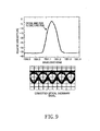
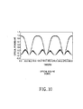
- FIGs. 6 to 10 are graphs showing the operation process of the optical transmission system according to the present invention.
- an optical carrier generated in the semiconductor laser 30 is applied to the optical phase modulator 103.
- Non-Return-to-Zero (NRZ) data are applied through the duobinary precoder 101 and then amplified in the driving amplifier 102.
- the amplified binary data having information of '0' or '1' have an optical phase changing according to the applied NRZ bit.
- the NRZ data are amplified through the duobinary precoder 101 and the driving amplifier 102 and then phase-modulated by the optical phase modulator 103.
- FIG. 6 shows the phase-modulated NRZ data, in which the inputted bit of '0' or '1' has been modulated by the optical phase modulator 103 into a phase information having a phase difference of '0' or ' ⁇ ' in an electric field.
- FIG. 7 shows the result obtained by filtering the phase-modulated signal by the optical band pass filter 104.
- the optical signal phase-modulated by the optical phase modulator 103 passes through the optical band pass filter 104 having a bit rate of 0.7/T.
- the optical band pass filter 104 filters the optical signal to eliminate other portions but the portion indicated by the broken line in the graph shown in FIG. 8.
- the optical signal having passed through the optical band pass filter 104 is converted to the duobinary signal as shown in FIG 9.
- the converted duobinary signal is inputted to the chirp-free Mach-Zehnder modulator 201 of the carrier suppressed RZ section 200, so that it can be converted to a DCS-RZ signal.
- a clock signal having a cycle which is typically half or two times of the bit-rate, is applied to an intensity modulator to modulate an incident NRZ signal to the RZ signal.
- the duobinary signal outputted from the optical band pass filter 104 is applied to the chirp-free Mach-Zehnder modulator 201, and a clock signal with 2T at a null point of a delivery curve is applied to the chirp-free Mach-Zehnder modulator 201, so as to generate a carrier suppressed RZ signal.
- the converted duobinary optical signal is outputted in the form of the DCS-RZ signal as shown in FIG 10 from the carrier suppressed RZ section 200.
- the present invention provides an optical transmission system using an optical phase modulator, which has no dependency of the transmission quality on the filtering characteristic and the bit pattern, and can remarkably improve the non-linearity and dispersion characteristics of the NRZ transmission during a high-speed WDM transmission of more than 10 Gbps.
- the present invention provides a duobinary carrier suppressed, return-to-zero (DCS-RZ) generating transmitter using an optical phase modulator, which is simpler than the conventional duobinary transmitter, and can overcome limitation in the transmission quality caused by the electric low-pass-filter, thereby realizing an effective high-speed high-density WDM transmission node.
- DCS-RZ duobinary carrier suppressed, return-to-zero
- DCS-RZ generating transmitter may be employed in optical transponders, optical transmitters, optical transceivers and WDM optical transmission systems, SONET/SDH, Ethernet transmission systems, etc.
Landscapes
- Physics & Mathematics (AREA)
- Electromagnetism (AREA)
- Engineering & Computer Science (AREA)
- Computer Networks & Wireless Communication (AREA)
- Signal Processing (AREA)
- Optics & Photonics (AREA)
- Nonlinear Science (AREA)
- Optical Communication System (AREA)
- Optical Modulation, Optical Deflection, Nonlinear Optics, Optical Demodulation, Optical Logic Elements (AREA)
Claims (4)
- Système de transmission optique comprenant :une section de modulation duobinaire (100) destinée à recevoir une porteuse et des données de non-retour à zéro, destinée à moduler les phases de la porteuse et des données de non-retour à zéro et destinée à filtrer la porteuse et les données de non-retour à zéro, de manière à fournir en sortie un signal de non-retour à zéro duobinaire, etune section de retour à zéro à porteuse supprimée (200), dans laquelle le signal de non-retour à zéro duobinaire provenant de la section de modulation duobinaire (100) est reçu en entrée et un signal d'horloge ayant un cycle 2T est appliqué à un modulateur (201) de manière à fournir en sortie un signal de retour à zéro à porteuse supprimée,où la section de modulation duobinaire (100) comprend :un module de précodage différentiel (101) destiné à coder les données de non-retour à zéro,un modulateur de phase optique (103) destiné à amplifier les données de non-retour à zéro, qui ont été codées dans le module de précodage différentiel (101) pour convertir les données de non-retour à zéro en un signal optique comportant une information de phase optique avec une différence de phase prédéterminée, etun filtre passe-bande optique (104) destiné à filtrer le signal optique modulé en phase ayant une bande passante correspondant à un débit binaire de 0,7/T, qui a fait l'objet d'une modulation de phase par le modulateur de phase optique, afin de fournir en sortie un signal duobinaire.
- Système de transmission optique selon la revendication 1, dans lequel les positions de la section de modulation duobinaire (100) et de la section de retour à zéro à porteuse supprimée (200) peuvent être interchangées.
- Système de transmission optique selon la revendication 1, dans lequel les caractéristiques du modulateur de phase peuvent être sélectivement réglées en réglant un indice de modulation, qui indique un degré de modulation de phase.
- Système de transmission optique selon la revendication 1, dans lequel la section de retour à zéro à porteuse supprimée (200) comprend un modulateur de Mach-Zender exempt d'ondulations (201) destiné à recevoir le signal de non-retour à zéro duobinaire de la section de modulation duobinaire (100) et un signal d'horloge présentant un cycle prédéterminé à un point zéro d'une courbe de délivrance, de manière à générer un signal à porteuse supprimée.
Applications Claiming Priority (2)
| Application Number | Priority Date | Filing Date | Title |
|---|---|---|---|
| KR10-2002-0075367A KR100480274B1 (ko) | 2002-11-29 | 2002-11-29 | 광위상변조기를 이용한 광전송시스템 |
| KR2002075367 | 2002-11-29 |
Publications (3)
| Publication Number | Publication Date |
|---|---|
| EP1424795A2 EP1424795A2 (fr) | 2004-06-02 |
| EP1424795A3 EP1424795A3 (fr) | 2005-09-21 |
| EP1424795B1 true EP1424795B1 (fr) | 2007-10-17 |
Family
ID=32291827
Family Applications (1)
| Application Number | Title | Priority Date | Filing Date |
|---|---|---|---|
| EP03015980A Expired - Fee Related EP1424795B1 (fr) | 2002-11-29 | 2003-07-14 | Système de transmission optique utilisant un modulateur de phase optique |
Country Status (5)
| Country | Link |
|---|---|
| US (1) | US20040105686A1 (fr) |
| EP (1) | EP1424795B1 (fr) |
| JP (1) | JP3984219B2 (fr) |
| KR (1) | KR100480274B1 (fr) |
| DE (1) | DE60316901T2 (fr) |
Families Citing this family (11)
| Publication number | Priority date | Publication date | Assignee | Title |
|---|---|---|---|---|
| KR100600996B1 (ko) * | 2003-10-24 | 2006-07-19 | 한국전자통신연구원 | 광통신 시스템을 위한 분산 특성이 강한 듀오바이너리csrz 및 csrz-dpsk 광신호 발생 광송신기 |
| KR100592878B1 (ko) * | 2003-12-18 | 2006-06-23 | 한국전자통신연구원 | 전기적으로 대역 제한된 광학적 디피에스케이(dpsk)변조 장치 및 방법 |
| JP4663997B2 (ja) * | 2004-03-09 | 2011-04-06 | 富士通株式会社 | 広入力ダイナミックレンジ光増幅器を用いた光伝送装置 |
| US7466926B2 (en) * | 2004-05-28 | 2008-12-16 | Alcatel-Lucent Usa Inc. | Method and apparatus for RZ-DPSK optical signal generation |
| KR100703413B1 (ko) * | 2005-03-28 | 2007-04-03 | 삼성전자주식회사 | 편광 듀오바이너리 광송신기 |
| US7634200B2 (en) * | 2005-06-22 | 2009-12-15 | National Central University | Method and apparatus for transporting ethernet and radio frequency signals in fiber-optic system |
| EP2034634A4 (fr) | 2006-06-19 | 2013-10-16 | Fujitsu Ltd | Processeur de signal optique |
| US8238757B2 (en) * | 2007-01-18 | 2012-08-07 | Futurewei Technologies, Inc. | Method and apparatus for generating optical duobinary signals with enhanced receiver sensitivity and spectral efficiency |
| CN101150370A (zh) * | 2007-04-12 | 2008-03-26 | 中兴通讯股份有限公司 | Rz-dpsk调制光信号产生装置及方法 |
| US8433202B2 (en) * | 2009-05-20 | 2013-04-30 | Neophotonics Corporation | 40, 50 and 100 Gb/s optical transceivers/transponders in 300pin and CFP MSA modules |
| CN102355304B (zh) * | 2011-07-20 | 2014-08-06 | 上海交通大学 | 以太网波分复用传输系统及其发射端 |
Family Cites Families (6)
| Publication number | Priority date | Publication date | Assignee | Title |
|---|---|---|---|---|
| JP3306573B2 (ja) * | 1994-09-12 | 2002-07-24 | 日本電信電話株式会社 | 光送信装置および光伝送システム |
| DE69940873D1 (de) * | 1998-07-29 | 2009-06-25 | Nippon Telegraph & Telephone | Optisches Übertragungssystem |
| US7536108B2 (en) * | 2001-06-29 | 2009-05-19 | Nippon Telegraph & Telephone Corporation | High precision chromatic dispersion measuring method and automatic dispersion compensating optical link system that uses this method |
| KR100493095B1 (ko) * | 2002-10-16 | 2005-06-02 | 삼성전자주식회사 | 광 전송 시스템 |
| KR100469709B1 (ko) * | 2002-11-22 | 2005-02-02 | 삼성전자주식회사 | 듀오바이너리 광 전송장치 |
| KR100469740B1 (ko) * | 2002-11-27 | 2005-02-02 | 삼성전자주식회사 | 듀오바이너리 광 전송장치 |
-
2002
- 2002-11-29 KR KR10-2002-0075367A patent/KR100480274B1/ko not_active IP Right Cessation
-
2003
- 2003-05-20 US US10/441,377 patent/US20040105686A1/en not_active Abandoned
- 2003-07-14 DE DE60316901T patent/DE60316901T2/de not_active Expired - Lifetime
- 2003-07-14 EP EP03015980A patent/EP1424795B1/fr not_active Expired - Fee Related
- 2003-11-20 JP JP2003390719A patent/JP3984219B2/ja not_active Expired - Fee Related
Also Published As
| Publication number | Publication date |
|---|---|
| EP1424795A2 (fr) | 2004-06-02 |
| JP3984219B2 (ja) | 2007-10-03 |
| DE60316901T2 (de) | 2008-02-07 |
| US20040105686A1 (en) | 2004-06-03 |
| JP2004312676A (ja) | 2004-11-04 |
| EP1424795A3 (fr) | 2005-09-21 |
| KR100480274B1 (ko) | 2005-04-07 |
| DE60316901D1 (de) | 2007-11-29 |
| KR20040047236A (ko) | 2004-06-05 |
Similar Documents
| Publication | Publication Date | Title |
|---|---|---|
| EP1511195B1 (fr) | Dispositif de transmission optique duobinaire utilisant un amplificateur optique à semi-conducteur | |
| EP1404036B1 (fr) | Dispositif de transmission optique duobinaire | |
| EP1424795B1 (fr) | Système de transmission optique utilisant un modulateur de phase optique | |
| KR100520648B1 (ko) | 반도체 광 증폭기를 이용한 듀오바이너리 광 전송장치 | |
| EP1416654B1 (fr) | Transmission duobinaire optique | |
| JP2000106543A (ja) | 光伝送装置 | |
| US7206519B2 (en) | Duobinary optical transmission apparatus | |
| KR100493095B1 (ko) | 광 전송 시스템 | |
| EP1487137A1 (fr) | Emetteur optique duo-binaire à polarization modulée | |
| KR100592878B1 (ko) | 전기적으로 대역 제한된 광학적 디피에스케이(dpsk)변조 장치 및 방법 | |
| US7215892B2 (en) | Duobinary optical transmitter | |
| KR100480283B1 (ko) | 듀오바이너리 광 전송장치 | |
| EP1515461B1 (fr) | Emetteur optique duobinaire | |
| KR100469740B1 (ko) | 듀오바이너리 광 전송장치 | |
| EP1473856B1 (fr) | Dispositif de transmission optique duobinaire | |
| JP2010287915A (ja) | 光送信装置、光通信装置および光送信方法 |
Legal Events
| Date | Code | Title | Description |
|---|---|---|---|
| PUAI | Public reference made under article 153(3) epc to a published international application that has entered the european phase |
Free format text: ORIGINAL CODE: 0009012 |
|
| 17P | Request for examination filed |
Effective date: 20030714 |
|
| AK | Designated contracting states |
Kind code of ref document: A2 Designated state(s): AT BE BG CH CY CZ DE DK EE ES FI FR GB GR HU IE IT LI LU MC NL PT RO SE SI SK TR |
|
| AX | Request for extension of the european patent |
Extension state: AL LT LV MK |
|
| PUAL | Search report despatched |
Free format text: ORIGINAL CODE: 0009013 |
|
| AK | Designated contracting states |
Kind code of ref document: A3 Designated state(s): AT BE BG CH CY CZ DE DK EE ES FI FR GB GR HU IE IT LI LU MC NL PT RO SE SI SK TR |
|
| AX | Request for extension of the european patent |
Extension state: AL LT LV MK |
|
| RIC1 | Information provided on ipc code assigned before grant |
Ipc: 7H 04B 10/155 A Ipc: 7H 04B 10/18 B |
|
| AKX | Designation fees paid |
Designated state(s): DE FR GB |
|
| GRAP | Despatch of communication of intention to grant a patent |
Free format text: ORIGINAL CODE: EPIDOSNIGR1 |
|
| GRAS | Grant fee paid |
Free format text: ORIGINAL CODE: EPIDOSNIGR3 |
|
| GRAA | (expected) grant |
Free format text: ORIGINAL CODE: 0009210 |
|
| AK | Designated contracting states |
Kind code of ref document: B1 Designated state(s): DE FR GB |
|
| REG | Reference to a national code |
Ref country code: GB Ref legal event code: FG4D |
|
| REF | Corresponds to: |
Ref document number: 60316901 Country of ref document: DE Date of ref document: 20071129 Kind code of ref document: P |
|
| ET | Fr: translation filed | ||
| PLBE | No opposition filed within time limit |
Free format text: ORIGINAL CODE: 0009261 |
|
| STAA | Information on the status of an ep patent application or granted ep patent |
Free format text: STATUS: NO OPPOSITION FILED WITHIN TIME LIMIT |
|
| 26N | No opposition filed |
Effective date: 20080718 |
|
| REG | Reference to a national code |
Ref country code: FR Ref legal event code: PLFP Year of fee payment: 14 |
|
| PGFP | Annual fee paid to national office [announced via postgrant information from national office to epo] |
Ref country code: GB Payment date: 20160615 Year of fee payment: 14 |
|
| PGFP | Annual fee paid to national office [announced via postgrant information from national office to epo] |
Ref country code: FR Payment date: 20160615 Year of fee payment: 14 |
|
| PGFP | Annual fee paid to national office [announced via postgrant information from national office to epo] |
Ref country code: DE Payment date: 20160614 Year of fee payment: 14 |
|
| REG | Reference to a national code |
Ref country code: DE Ref legal event code: R119 Ref document number: 60316901 Country of ref document: DE |
|
| GBPC | Gb: european patent ceased through non-payment of renewal fee |
Effective date: 20170714 |
|
| REG | Reference to a national code |
Ref country code: FR Ref legal event code: ST Effective date: 20180330 |
|
| PG25 | Lapsed in a contracting state [announced via postgrant information from national office to epo] |
Ref country code: DE Free format text: LAPSE BECAUSE OF NON-PAYMENT OF DUE FEES Effective date: 20180201 Ref country code: GB Free format text: LAPSE BECAUSE OF NON-PAYMENT OF DUE FEES Effective date: 20170714 |
|
| PG25 | Lapsed in a contracting state [announced via postgrant information from national office to epo] |
Ref country code: FR Free format text: LAPSE BECAUSE OF NON-PAYMENT OF DUE FEES Effective date: 20170731 |