EP1424589A1 - Procede pour commander un element d'affichage a cristaux liquides et affichage a cristaux liquides faisant appel audit procede - Google Patents
Procede pour commander un element d'affichage a cristaux liquides et affichage a cristaux liquides faisant appel audit procede Download PDFInfo
- Publication number
- EP1424589A1 EP1424589A1 EP02733261A EP02733261A EP1424589A1 EP 1424589 A1 EP1424589 A1 EP 1424589A1 EP 02733261 A EP02733261 A EP 02733261A EP 02733261 A EP02733261 A EP 02733261A EP 1424589 A1 EP1424589 A1 EP 1424589A1
- Authority
- EP
- European Patent Office
- Prior art keywords
- pixels
- liquid crystal
- source
- crystal display
- picture signal
- Prior art date
- Legal status (The legal status is an assumption and is not a legal conclusion. Google has not performed a legal analysis and makes no representation as to the accuracy of the status listed.)
- Withdrawn
Links
- 239000004973 liquid crystal related substance Substances 0.000 title claims abstract description 169
- 238000000034 method Methods 0.000 title claims abstract description 35
- 239000003086 colorant Substances 0.000 claims description 10
- 239000011159 matrix material Substances 0.000 claims description 8
- 230000007704 transition Effects 0.000 description 13
- 230000014759 maintenance of location Effects 0.000 description 11
- 230000004044 response Effects 0.000 description 9
- 230000000717 retained effect Effects 0.000 description 8
- 230000000694 effects Effects 0.000 description 6
- 239000000758 substrate Substances 0.000 description 5
- 230000008859 change Effects 0.000 description 4
- 238000010586 diagram Methods 0.000 description 2
- 230000005684 electric field Effects 0.000 description 2
- 230000003071 parasitic effect Effects 0.000 description 2
- 230000002265 prevention Effects 0.000 description 2
- 230000000630 rising effect Effects 0.000 description 2
- 238000010276 construction Methods 0.000 description 1
- 230000008878 coupling Effects 0.000 description 1
- 238000010168 coupling process Methods 0.000 description 1
- 238000005859 coupling reaction Methods 0.000 description 1
- 210000002858 crystal cell Anatomy 0.000 description 1
- 230000006866 deterioration Effects 0.000 description 1
- 238000011161 development Methods 0.000 description 1
- 230000018109 developmental process Effects 0.000 description 1
- 238000003780 insertion Methods 0.000 description 1
- 230000037431 insertion Effects 0.000 description 1
- 150000002500 ions Chemical class 0.000 description 1
- 230000004048 modification Effects 0.000 description 1
- 238000012986 modification Methods 0.000 description 1
- 230000003068 static effect Effects 0.000 description 1
- 239000010409 thin film Substances 0.000 description 1
Images


Classifications
-
- G—PHYSICS
- G09—EDUCATION; CRYPTOGRAPHY; DISPLAY; ADVERTISING; SEALS
- G09G—ARRANGEMENTS OR CIRCUITS FOR CONTROL OF INDICATING DEVICES USING STATIC MEANS TO PRESENT VARIABLE INFORMATION
- G09G3/00—Control arrangements or circuits, of interest only in connection with visual indicators other than cathode-ray tubes
- G09G3/20—Control arrangements or circuits, of interest only in connection with visual indicators other than cathode-ray tubes for presentation of an assembly of a number of characters, e.g. a page, by composing the assembly by combination of individual elements arranged in a matrix no fixed position being assigned to or needed to be assigned to the individual characters or partial characters
- G09G3/34—Control arrangements or circuits, of interest only in connection with visual indicators other than cathode-ray tubes for presentation of an assembly of a number of characters, e.g. a page, by composing the assembly by combination of individual elements arranged in a matrix no fixed position being assigned to or needed to be assigned to the individual characters or partial characters by control of light from an independent source
- G09G3/36—Control arrangements or circuits, of interest only in connection with visual indicators other than cathode-ray tubes for presentation of an assembly of a number of characters, e.g. a page, by composing the assembly by combination of individual elements arranged in a matrix no fixed position being assigned to or needed to be assigned to the individual characters or partial characters by control of light from an independent source using liquid crystals
- G09G3/3611—Control of matrices with row and column drivers
- G09G3/3614—Control of polarity reversal in general
-
- G—PHYSICS
- G02—OPTICS
- G02F—OPTICAL DEVICES OR ARRANGEMENTS FOR THE CONTROL OF LIGHT BY MODIFICATION OF THE OPTICAL PROPERTIES OF THE MEDIA OF THE ELEMENTS INVOLVED THEREIN; NON-LINEAR OPTICS; FREQUENCY-CHANGING OF LIGHT; OPTICAL LOGIC ELEMENTS; OPTICAL ANALOGUE/DIGITAL CONVERTERS
- G02F1/00—Devices or arrangements for the control of the intensity, colour, phase, polarisation or direction of light arriving from an independent light source, e.g. switching, gating or modulating; Non-linear optics
- G02F1/01—Devices or arrangements for the control of the intensity, colour, phase, polarisation or direction of light arriving from an independent light source, e.g. switching, gating or modulating; Non-linear optics for the control of the intensity, phase, polarisation or colour
- G02F1/13—Devices or arrangements for the control of the intensity, colour, phase, polarisation or direction of light arriving from an independent light source, e.g. switching, gating or modulating; Non-linear optics for the control of the intensity, phase, polarisation or colour based on liquid crystals, e.g. single liquid crystal display cells
- G02F1/133—Constructional arrangements; Operation of liquid crystal cells; Circuit arrangements
-
- G—PHYSICS
- G09—EDUCATION; CRYPTOGRAPHY; DISPLAY; ADVERTISING; SEALS
- G09G—ARRANGEMENTS OR CIRCUITS FOR CONTROL OF INDICATING DEVICES USING STATIC MEANS TO PRESENT VARIABLE INFORMATION
- G09G2300/00—Aspects of the constitution of display devices
- G09G2300/04—Structural and physical details of display devices
- G09G2300/0469—Details of the physics of pixel operation
- G09G2300/0478—Details of the physics of pixel operation related to liquid crystal pixels
- G09G2300/0491—Use of a bi-refringent liquid crystal, optically controlled bi-refringence [OCB] with bend and splay states, or electrically controlled bi-refringence [ECB] for controlling the color
-
- G—PHYSICS
- G09—EDUCATION; CRYPTOGRAPHY; DISPLAY; ADVERTISING; SEALS
- G09G—ARRANGEMENTS OR CIRCUITS FOR CONTROL OF INDICATING DEVICES USING STATIC MEANS TO PRESENT VARIABLE INFORMATION
- G09G2310/00—Command of the display device
- G09G2310/02—Addressing, scanning or driving the display screen or processing steps related thereto
- G09G2310/0202—Addressing of scan or signal lines
- G09G2310/0205—Simultaneous scanning of several lines in flat panels
-
- G—PHYSICS
- G09—EDUCATION; CRYPTOGRAPHY; DISPLAY; ADVERTISING; SEALS
- G09G—ARRANGEMENTS OR CIRCUITS FOR CONTROL OF INDICATING DEVICES USING STATIC MEANS TO PRESENT VARIABLE INFORMATION
- G09G2310/00—Command of the display device
- G09G2310/02—Addressing, scanning or driving the display screen or processing steps related thereto
- G09G2310/0235—Field-sequential colour display
-
- G—PHYSICS
- G09—EDUCATION; CRYPTOGRAPHY; DISPLAY; ADVERTISING; SEALS
- G09G—ARRANGEMENTS OR CIRCUITS FOR CONTROL OF INDICATING DEVICES USING STATIC MEANS TO PRESENT VARIABLE INFORMATION
- G09G2310/00—Command of the display device
- G09G2310/02—Addressing, scanning or driving the display screen or processing steps related thereto
- G09G2310/0243—Details of the generation of driving signals
- G09G2310/0251—Precharge or discharge of pixel before applying new pixel voltage
-
- G—PHYSICS
- G09—EDUCATION; CRYPTOGRAPHY; DISPLAY; ADVERTISING; SEALS
- G09G—ARRANGEMENTS OR CIRCUITS FOR CONTROL OF INDICATING DEVICES USING STATIC MEANS TO PRESENT VARIABLE INFORMATION
- G09G2310/00—Command of the display device
- G09G2310/06—Details of flat display driving waveforms
-
- G—PHYSICS
- G09—EDUCATION; CRYPTOGRAPHY; DISPLAY; ADVERTISING; SEALS
- G09G—ARRANGEMENTS OR CIRCUITS FOR CONTROL OF INDICATING DEVICES USING STATIC MEANS TO PRESENT VARIABLE INFORMATION
- G09G2310/00—Command of the display device
- G09G2310/06—Details of flat display driving waveforms
- G09G2310/061—Details of flat display driving waveforms for resetting or blanking
-
- G—PHYSICS
- G09—EDUCATION; CRYPTOGRAPHY; DISPLAY; ADVERTISING; SEALS
- G09G—ARRANGEMENTS OR CIRCUITS FOR CONTROL OF INDICATING DEVICES USING STATIC MEANS TO PRESENT VARIABLE INFORMATION
- G09G2320/00—Control of display operating conditions
- G09G2320/02—Improving the quality of display appearance
- G09G2320/0252—Improving the response speed
-
- G—PHYSICS
- G09—EDUCATION; CRYPTOGRAPHY; DISPLAY; ADVERTISING; SEALS
- G09G—ARRANGEMENTS OR CIRCUITS FOR CONTROL OF INDICATING DEVICES USING STATIC MEANS TO PRESENT VARIABLE INFORMATION
- G09G2320/00—Control of display operating conditions
- G09G2320/02—Improving the quality of display appearance
- G09G2320/0257—Reduction of after-image effects
-
- G—PHYSICS
- G09—EDUCATION; CRYPTOGRAPHY; DISPLAY; ADVERTISING; SEALS
- G09G—ARRANGEMENTS OR CIRCUITS FOR CONTROL OF INDICATING DEVICES USING STATIC MEANS TO PRESENT VARIABLE INFORMATION
- G09G2320/00—Control of display operating conditions
- G09G2320/02—Improving the quality of display appearance
- G09G2320/0261—Improving the quality of display appearance in the context of movement of objects on the screen or movement of the observer relative to the screen
-
- G—PHYSICS
- G09—EDUCATION; CRYPTOGRAPHY; DISPLAY; ADVERTISING; SEALS
- G09G—ARRANGEMENTS OR CIRCUITS FOR CONTROL OF INDICATING DEVICES USING STATIC MEANS TO PRESENT VARIABLE INFORMATION
- G09G3/00—Control arrangements or circuits, of interest only in connection with visual indicators other than cathode-ray tubes
- G09G3/20—Control arrangements or circuits, of interest only in connection with visual indicators other than cathode-ray tubes for presentation of an assembly of a number of characters, e.g. a page, by composing the assembly by combination of individual elements arranged in a matrix no fixed position being assigned to or needed to be assigned to the individual characters or partial characters
- G09G3/34—Control arrangements or circuits, of interest only in connection with visual indicators other than cathode-ray tubes for presentation of an assembly of a number of characters, e.g. a page, by composing the assembly by combination of individual elements arranged in a matrix no fixed position being assigned to or needed to be assigned to the individual characters or partial characters by control of light from an independent source
- G09G3/36—Control arrangements or circuits, of interest only in connection with visual indicators other than cathode-ray tubes for presentation of an assembly of a number of characters, e.g. a page, by composing the assembly by combination of individual elements arranged in a matrix no fixed position being assigned to or needed to be assigned to the individual characters or partial characters by control of light from an independent source using liquid crystals
- G09G3/3611—Control of matrices with row and column drivers
- G09G3/3648—Control of matrices with row and column drivers using an active matrix
-
- G—PHYSICS
- G09—EDUCATION; CRYPTOGRAPHY; DISPLAY; ADVERTISING; SEALS
- G09G—ARRANGEMENTS OR CIRCUITS FOR CONTROL OF INDICATING DEVICES USING STATIC MEANS TO PRESENT VARIABLE INFORMATION
- G09G3/00—Control arrangements or circuits, of interest only in connection with visual indicators other than cathode-ray tubes
- G09G3/20—Control arrangements or circuits, of interest only in connection with visual indicators other than cathode-ray tubes for presentation of an assembly of a number of characters, e.g. a page, by composing the assembly by combination of individual elements arranged in a matrix no fixed position being assigned to or needed to be assigned to the individual characters or partial characters
- G09G3/34—Control arrangements or circuits, of interest only in connection with visual indicators other than cathode-ray tubes for presentation of an assembly of a number of characters, e.g. a page, by composing the assembly by combination of individual elements arranged in a matrix no fixed position being assigned to or needed to be assigned to the individual characters or partial characters by control of light from an independent source
- G09G3/36—Control arrangements or circuits, of interest only in connection with visual indicators other than cathode-ray tubes for presentation of an assembly of a number of characters, e.g. a page, by composing the assembly by combination of individual elements arranged in a matrix no fixed position being assigned to or needed to be assigned to the individual characters or partial characters by control of light from an independent source using liquid crystals
- G09G3/3611—Control of matrices with row and column drivers
- G09G3/3674—Details of drivers for scan electrodes
- G09G3/3677—Details of drivers for scan electrodes suitable for active matrices only
Definitions
- the present invention relates to a method of driving a liquid crystal display element and a liquid crystal display device using the method and, particularly, to the liquid crystal display device employing a liquid crystal mode capable of achieving a high speed response and a wide angle of visibility.
- An active matrix type liquid crystal display using a thin film transistor is used in various fields such as a display of a camcorder and a display of a personal computer or a personal word processor owing to its advantages such as a reduced thickness, a reduced weight, and capability of low voltage driving, and there is a large market for such liquid crystal display.
- TFT thin film transistor
- liquid crystal display has been used for displaying dynamic images and has been applied to televisions in addition to the conventional use for displaying static images in a personal computer and the like, and there is an increasing demand for a liquid crystal display device suitable for such dynamic image display.
- a liquid crystal display element of a bend orientation is proposed in Japanese Unexamined Patent Publication No. 7-84254 as the liquid crystal element which enables improvements in high speed response required for the dynamic image display.
- liquid crystals rapidly change with a change of voltage, thereby realizing the high speed response.
- Japanese Unexamined Patent Publication No. 11-109921 proposes a driving method of a liquid crystal display element, wherein a blanking image is displayed using a non-image signal which is inserted between picture signals so as to reduce a blurring of dynamic image which is peculiar to the liquid crystals.
- Fig. 12 is a timing chart indicating contents of gate signals and a source signal in the conventional liquid crystal display element driving method, wherein Fig. 12A is a graph showing the gate signals and Fig. 12B is a graph showing the source signal.
- a gate ON voltage Vgon is applied to gate lines sequentially using gate signals Sg1 to Sgend, thereby bringing switching elements provided for respective pixels to an ON state. Then, a source signal Ssn is supplied from each of source lines to each of the pixels in accordance with the switching ON timing, and a potential difference between a pixel electrode and a counter electrode reaches a value responsive to a voltage applied by the source signal Ssn.
- a state in which a potential difference between a pixel electrode and a counter electrode in a certain pixel becomes a predetermined voltage by the source signal Ssn is expressed as the source signal is written to the pixel.
- the gate ON voltage Vgon is applied twice to each of the gate lines during each of frame periods Po and Pe; a picture signal 101 from the source line is written as the source signal Ssn to each of the pixels in the first Vgon application, and a non-picture signal 102 from the source line is written as the source signal Ssn to each of the pixels in the second Vgon application. Owing to the writing of non-picture signal 102, the reverse transition of liquid crystals to the splay orientation is prevented in each of the pixel.
- a liquid crystal display element is AC driven for the purpose of suppressing burn-in of liquid crystals and generation of display unevenness due to ions. Accordingly, the non-picture signal 102 is written to the pixels when applying the second gate ON voltage Vgon during the odd frame period Po, and then the picture signal 101 having a reverse polarity is written to the pixels when applying the first gate ON voltage Vgon during the succeeding even frame period Pe. Therefore, the writing of the picture signal 101 causes a great potential difference, and the potential of the pixel electrode does not reach the potential responsive to the picture signal 101 to lead to generation of the display unevenness.
- the present invention has been accomplished in view of the above problems, and a first object thereof is to provide a liquid crystal display element driving method and a liquid crystal display device using the method which enable a picture signal to be rapidly written to a pixel in the case where a plurality of times of signal writings are performed for each of the pixels during each of frame periods as in a liquid crystal display of a bend orientation.
- a second object of the invention is to provide a liquid crystal display element driving method and a liquid crystal display device using the method which enable a picture signal to be written to a pixel with reliability in the case of high resolution display.
- a liquid crystal display element driving method or a liquid crystal display device using the method according to the invention uses a liquid crystal display element having a plurality of pixels constituting a screen and comprises a gate driving step or gate driving means of dividing a frame period into a plurality of write periods and outputting gate signals to select the pixels sequentially during the write periods and a source driving step or source driving means of forming each of source signals such that the source signal includes a picture signal and a non-picture signal assigned for the write periods and writing each of the source signals corresponding to the selected pixels to each of the pixels with its polarity being alternated, thereby controlling a transmittivity of liquid crystals of each of the pixels in accordance with the written source signal to display an image responsive to the source signals on the screen of the liquid crystal display element, wherein the source driving step or the source driving means enables to write the non-picture signal to the pixel with its polarity being identical to that of the picture signal to be written subsequently.
- the non-picture signal may be written to the pixel at least during a last one of the plurality of write periods in the source driving step or by the source driving means.
- the non-picture signal may be written to the pixel at least during a first one of the plurality of write periods in the source driving step or by the source driving means.
- the picture signal and the non-picture signal may have the same polarity during the frame period.
- an amplitude between the picture signal and the non-picture signal is reduced during the frame period, thereby reducing time required for a potential of the source signal to reach a desired signal potential of each of the pixels and suppressing influences of resistance in the source line and signal delay due to parasitic capacitance. Therefore, it is possible to write the picture signal to the pixel more rapidly. Further, it is possible to reduce a load on the source driving means for supplying the source signal.
- the pixels may be selected during a plurality of periods in at least one of the plurality of write periods in the gate driving step or by the gate driving means, and the non-picture signal may be written to the selected pixels during the plurality of periods in the gate driving step or by the gate driving means.
- the plurality of periods may be consecutive.
- a liquid crystal display element driving method and the liquid crystal display device using the method according to the invention uses a liquid crystal display element having a plurality of pixels constituting a screen and comprises a gate driving step or gate driving means for dividing a frame period into four or more write periods and outputting gate signals to select the pixels sequentially during the write periods and a source driving step or source driving means for forming each of source signals such that the source signal includes picture signals corresponding to three colors of red, green, and blue assigned respectively for three write periods of the four or more write periods and writing each of the source signals corresponding to the selected pixels to each of the pixels with its polarity being alternated, thereby controlling a transmittivity of liquid crystals of each of the pixels in accordance with the written source signal to display a color image responsive to the source signals on the screen of the liquid crystal display element.
- each of the source signals may be formed such that the source signal includes at least one non-picture signal assigned for the write period other than the write periods in which the picture signals corresponding to the three colors of red, green, and blue are written.
- the non-picture signal may be written to the pixels during at least a last one of the four or more write periods.
- the non-picture signal may be written to the pixels during at least a first one of the four or more write periods.
- the picture signals may be written to the pixels with their polarities being alternated.
- the liquid crystals are AC driven with a higher frequency thereby to further suppress display unevenness.
- a liquid crystal display element driving method and the liquid crystal display device using the method according to the invention uses a liquid crystal display element having a plurality of pixels constituting a screen and comprises a gate driving step or gate driving means for dividing a frame period into three write periods and outputting gate signals to select the pixels sequentially during the write periods and a source driving step or source driving means for forming each of source signals such that the source signal includes picture signals corresponding to three colors of red, green, and blue assigned respectively for the three write periods and writing each of the source signals corresponding to the selected pixels to each of the pixels with its polarity being alternated, thereby controlling a transmittivity of liquid crystals of each of the pixels in accordance with the written source signal to display a color image responsive to the source signals on the screen of the liquid crystal display element, wherein the source driving step or the source driving means enables at least two consecutive ones of the picture signals to be written to the pixels with their polarities being identical to each other.
- the liquid crystals are AC driven with a higher frequency, thereby suppressing burn-in or display unevenness and flickering.
- the picture signals may be reversed in polarity every frame period.
- the pixels may be formed in matrix to be selected row by row or column by column sequentially in the gate driving step or by the gate driving means, and the source signals corresponding to the respective pixels selected row by row or column by column may be written sequentially row by row or column by column to the selected pixels in the source driving step or by the source driving means.
- the liquid crystal element is driven with a simple constitution.
- Fig. 1 is a block diagram showing an overall structure of a control system of a liquid crystal display device according to the first embodiment of the present invention.
- a liquid crystal display device 100 includes a liquid crystal display element 1, a gate driving circuit 4, and a source driving circuit 6, and a controller 8.
- the liquid crystal element 1 is a known one, and it is of the active matrix type in this embodiment.
- the liquid crystal display element 1 has a TFT substrate (not shown), a counter substrate (not shown) opposed to the TFT substrate, and liquid crystals disposed therebetween.
- a plurality of pixel electrodes 202 are formed in the shape of rows and columns (hereinafter referred to as matrix), and gate lines 3 and source lines 5 are disposed for the respective rows and columns of the pixel electrodes 202 in matrix.
- a region occupied by each of the pixel electrodes 202 as viewed from a direction of a thickness of the liquid crystal display element (more precisely, of a liquid crystal cell) is a pixel 2
- a region occupied by the overall pixels 2 is a screen.
- Each of the pixel electrodes 202 is connected to a relevant one of the source lines 5 via a switching element 203 and a relevant one of the gate lines 3 is connected to a gate of the switching element 203.
- the switching element 203 is formed by TFT, for example.
- Each of the pixels 2 has a common electrode 7a, and all the common electrodes 7a are electrically connected to one another and grounded by a common wiring 7.
- a counter electrode 201 is formed.
- Liquid crystal capacitance is denoted by Clc.
- Storage capacitance is denoted by Cst.
- the controller 8 supplies a picture signal, which is input externally, to the source driving circuit 6 and outputs a control signal to each of the source driving circuit 6 and the gate driving circuit 4, whereby the source driving circuit 6 and the gate driving circuit 4 are so controlled as to generate and output source signals Ss1 to Ssend and gate signals Sg1 to Sgend, respectively.
- the gate driving circuit 4 sends the gate signals Sg1 to Sgend to the switching elements 203 of the pixels 2 respectively via the gate lines 3 to bring the switching elements to ON state sequentially.
- the source driving circuit 6 sends the source signals Ss1 to Ssend to the pixel electrodes 202 respectively via the source lines 5.
- the source signals Ss1 to Ssend are sent in accordance with timings of the ON operations of the switching elements 203 of the pixels 2.
- electric fields respectively corresponding to the source signals Ss1 to Ssend are generated between the pixel electrodes 202 and the counter electrode 201, and transmittivities of the liquid crystals changes depending on the thus-generated electric fields.
- luminance of light emitted from a backlight (not shown) is modulated depending on the changes in transmittivity, and an image responsive to the source signals Ss1 to Ssend is displayed on the screen of the liquid crystal element 1.
- Figs. 2A and 2B constitute a timing chart showing contents of gate signals and a source signal in the liquid crystal display device of Fig. 1, wherein Fig. 2A is a graph showing the gate signals and Fig. 2B is a graph showing the source signal.
- the source driving circuit 6 is so constituted as to generate and output the source signals Ss1 to Ssend which are characteristic of this embodiment as shown in Fig. 2B.
- a source signal Ssn which is selected arbitrarily among the source signals Ss1 to Ssend output for the respective gate lines 5 is shown in Fig. 2B, the other source signals are similar to the source signal Ssn.
- the source signal Ssn is sectioned as to correspond to each frame. An odd frame period is denoted by Po, and an even frame period is denoted by Pe.
- Each of the frame periods Po and Pe is bisectioned into two write periods which are a first write period Poa for writing a picture signal to all the pixels 2 in one column and a second write period Pob for writing a non-picture signal in the same manner.
- the source signal Ssn is constituted of the picture signal 101 for the first write period Poa and the non-picture signal 102 for the second write period Pob.
- the first write period Poa and the second write period Pob are divided into periods Poa' (hereinafter referred to as pixel write periods) for writing the picture signal to each of the pixels 2 in one column and pixel write periods Pob' for writing the non-picture signal to each of the pixels in one column, respectively.
- the source signal Ssn has voltage values corresponding to predetermined display gradations for the respective pixel write periods Poa' and Pob'.
- a polarity is alternated in order to AC drive the liquid crystal element 1.
- the polarity is reversed every pixel write period (Poa', Pob'), and every frame period (Po, Pe). Also polarities of the first write period Poa during which the picture signal 101 is written and the second write period Pob during which the non-picture signal 102 is written are reversed from each other.
- a polarity of a non-picture signal write period (Pob in the drawing) in a certain frame period is identical to that of a picture signal write period (Pea in the drawing) in a succeeding frame period.
- VsB(+) and VsB(-) are voltage values for black display
- Vsup(+) and Vsup(-) are voltage values for non-picture signals.
- the gate driving circuit 4 is so constituted as to generate and output the gate signals Sg1 to Sgend which are similar to those of the conventional example.
- Each of the gate signals Sg1 to Sgend is a binary signal which has a voltage Vgon at a high level (hereinafter referred to as H level) and a voltage of Vgoff at a low level (hereinafter referred to as L level), and becomes the H level during the pixel write periods Poa', Pob', Pea', and Peb' of the relevant pixels 2 while becomes the L level during remaining retention periods Poa", Pob", Pea", and Peb".
- each of the gate signals Sg1 to Sgend becomes the H level twice in each of the frame periods Po and Pe; once in each of the first write periods Poa and Pea and once in each of the second write periods Pob and Peb.
- the gate signals Sg1 to Sgend are output, switching elements 203 of the pixels 2 are turned on row by row sequentially during the respective pixel write periods Poa', Pob', Pea', and Peb'.
- the picture signal 101 and the non-picture signal 102 of each of the source signals Ss1 to Ssend corresponding to each of the pixels 2 are written.
- Figs. 3A and Fig. 3B are graphs showing changes in potential of a certain pixel electrode in the liquid crystal display device of Fig. 1, wherein Fig. 3A is the graph showing the changes in black display, and Fig. 3B is the graph showing the changes in white display.
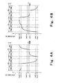
- Fig. 4A and 4B are graphs showing changes in potential of a pixel electrode, wherein Fig. 4A is the graph showing the changes in the case of switching from black display to white display in the liquid crystal display device of Fig. 1, and Fig. 4B is the graph showing the changes in the case of switching from black display to white display in the conventional example.
- Fig. 5 is a graph showing changes in luminance of liquid crystals of a certain pixel in the case of switching from black display to white display.
- the normally white mode is employed.
- the voltage Vgon at the H level of the gate signal Ssn is set at 15 V, and the voltage Vgoff at the L level of the signal Ssn is set at -10 V.
- An amplitude of the source signal Ssn is set with respect to the potential of the counter electrode 201 in such a manner that: the voltages Vsup(+) and Vsup(-) for the non-picture signal are +6 V and -6 V, respectively; VsB(+) and VsB(-) for the black display level are +5 V and -5 V, respectively; and VsW(+) and VsW(-) for the white display level are +1 V and - 1 V, respectively, and a duration of each of the frame periods is 16.6 ms (60 Hz). Further, a response in an arbitrary pixel 2 in the fist row among the pixels in matrix is described by way of example.
- a case of black display of a certain pixel 2 of the liquid crystal element 1 will be described.
- the picture signal 101 of the black display level of the source signal is input during the pixel write period Poa' of the first write period Poa of an odd frame Po.
- the potential of the pixel electrode 202 is changed from +6 V which is the voltage value Vsup(+) of the non-picture signal 102 of the preceding frame period to +5 V which is the black display level VsB(+). The value is retained during the retention period Poa".
- the non-picture signal 102 is input during the pixel write period Pob' of the second write period Pob.
- the potential of the pixel electrode 202 is changed from +5 V to -6 V which is the voltage value Vsup(-) of the non-picture signal. The value is retained during the retention period Pob".
- the picture signal 101 of the white level of the source signal Ssn is input during the pixel write period Pea' of the first write period Poa of the succeeding odd frame Pe.
- the potential of the pixel electrode 202 is changed from -6 V to -5 V which is the white display level VsW in accordance with a charge characteristic which depends on the capacity of the pixel 2. The value is retained during the retention period Pea". Then, the non-picture signal 102 is input during the pixel write period Peb' of the second write period Peb. In this case, the non-picture signal 102 has a polarity opposite to that of the picture signal 101, the potential of the pixel electrode 202 is changed from -5 V to +6 V which is the voltage value Vsup(+) of the non-picture signal 102. The value is retained during the retention period Peb" (not shown).
- the polarities of the non-picture signal 102 and the picture signal 101 are identical to each other. Therefore, it is possible to reduce the potential difference to be written, and, in this example, the potential difference is reduced to about 1 V. Consequently, it is possible to perform the writing of the picture signal 101 with a liberal allowance of time.
- the black display performed in accordance with this embodiment is failsafe.
- the white display of the pixel 2 of the liquid crystal element 1 will be described.
- the picture signal 101 is input during the pixel write period Poa' of the first write period Poa of the even frame Po.
- a potential of the pixel electrode 202 changes from +6 V which is the voltage value Vsup(+) of the non-picture signal 102 in the preceding frame period to +1 V which is the white display level VsW(+).
- the value is retained during the retention period Poa”.
- the non-picture signal 102 is input during the pixel write period Pob' of the second write period Pob.
- the potential of the pixel electrode 202 then changes from +1 V to -6 V which is the voltage value Vsup(-) of the non-picture signal 102. The value is retained during the retention period Pob". Then, the picture signal 101 of the white display level of the source signal Ssn is input during the pixel write period Pea of the first write period Poa of the next even frame Pe. Then, the potential of the pixel electrode changes from -6 V to -1 V which is the white display level VsW(-). The value is retained during the retention period Pea”. Next, the non-picture signal 102 is input during the pixel write period Peb' of the second write period Peb. Then, the potential of the pixel electrode 202 changes from -5 V to +6 V which is the voltage Vsup(+) of the non-picture signal 102. The value is retained during the retention period Peb" (not shown).
- the above-described white display is the case of performing the white display under the worst conditions in this embodiment; however, even in this worst case, it is possible to suppress the potential difference when writing the picture signal 101 after writing the non-picture signal 102 to about 5 V, and the signal writing is performed without any trouble.
- the liquid crystals may in some cases fail to perfectly transition to the white display state even when the potential difference is smaller than that of the black display.
- the potential difference in writing the picture signal is 5 V, as described above, which is smaller than that (7 V) achieved by the conventional example (see Fig. 4B), the white display is performed without any trouble.
- a pixel voltage drop called a punch-through voltage occurs in actuality due to a coupling of the capacity of the switching element 203 and the pixel capacity at the time point when the gate signal falls to bring the switching element 203 to the OFF state; however, explanation for such pixel voltage drop is omitted in order to simplify the description.
- Figs. 4A and 4B are graphs showing changes in potential of a certain pixel electrode in the case of switching from the black display to the white display, wherein Fig. 4A is the graph showing the changes in this embodiment, and Fig. 4B is the graph showing the changes in the conventional example.
- the non-picture signal 102 of the preceding frame period when switching from the black display to the white display in the conventional example, has a polarity opposite to that of the picture signal 101 of the white display of the succeeding frame period (the even frame period Pe in Fig. 4B) and has a larger voltage to be applied to liquid crystals.
- the non-picture signal 102 of the preceding frame period when switching from the black display to the white display, has the same polarity as the picture signal 101 of the white display of the succeeding frame period (the even frame period Pe in Fig.
- Fig. 5 is a graph showing changes in luminance of a liquid crystal display device with respect to time in the case of switching from the black display to the white display.
- the reference numeral 211 denotes a luminance change curve with respect to time of the liquid crystal display device according to this embodiment
- the reference numeral 212 denotes a luminance change curve with respect to time of the conventional liquid crystal display device.
- the response speed of the liquid crystals with respect to the switching from the black display to the white display of the liquid crystal display device according to this embodiment i.e. the time ⁇ 1 required for the luminance to transition from a black level to a white level, is shorter than a response speed ⁇ 2 of liquid crystals of the conventional liquid crystal display device.
- the liquid crystal display without unevenness on the whole screen is realized, and the effect of improving the response speed is achieved.
- the voltage Vsup may be set to a value identical to the black display potential.
- the non-picture signal is written after writing the picture signal in each of the frame periods in this embodiment
- the non-picture signal may be written before writing the picture signal.
- the similar effect is achieved by setting the polarities of the picture signal and the non-picture signal identical to each other in the frame period.
- the retention period after writing the picture signal and the retention period after writing the non-picture signal are identical in duration in this embodiment, the durations are not critical and may be different from each other. In that case, the display brightness, the reverse transition prevention effect, the sharpness of dynamic images, and the like are changed, but, in both of the cases, the signal writing ability is improved, and the display unevenness is suppressed.
- Fig. 6A and 6B constitute a timing chart showing contents of gate signals and a source signal in a liquid crystal display device according to the second embodiment of the invention, wherein Fig. 6A is a graph showing the gate signals and Fig. 6B is a graph showing the source signal.
- the reference numerals identical to those of Figs. 2A and 2B denote components identical or equivalent to those of Figs. 2A and 2B.
- a polarity of the picture signal 101 of the source signal Ssn remains unchanged during each of frame periods Po and Pe and a polarity of a non-picture signal 102 remains unchanged during each of the frame periods Po and Pe in this embodiment.
- Other parts of constitution are the same as the first embodiment.
- an amplitude of the source signal Ssn during the write periods Poa and Pea of the picture signal 101 and the write periods Pob and Peb of the non-picture signal 102 is reduced. Therefore, it is possible to reduce time required for a potential of the source signal to reach a desired signal potential of each of pixels and to suppress influence of signal delay due to resistance in source lines 5 and parasitic capacitance. Thus, signal writing ability is further improved. Further, a load on the driving circuit 6 for supplying the source signal Ssn is reduced.
- Fig. 7A and 7B constitute a timing chart showing contents of gate signals and a source signal in a liquid crystal display device according to a third embodiment of the invention, wherein Fig. 7A is a graph showing the gate signals and Fig. 7B is a graph showing the source signal.
- Figs. 7A and 7B the reference numerals identical to those of Figs. 2A and 2B denote components identical or equivalent to those of Figs. 2A and 2B.
- each of the pixel write periods Poa' and Pea' of the picture signal 101 is provided twice in each of the frame periods Po and Pe in this embodiment.
- the picture signal 101 to be written to the pixel is actually written in each of the latter pixel write periods.
- Other parts of constitution are the same as the first embodiment.
- the write period for the picture signal 101 is effectively increased, thereby further improving the ability of writing the picture signal 101.
- Fig. 8A and 8B constitute a timing chart showing contents of gate signals and a source signal in a liquid crystal display device according to a fourth embodiment of the invention, wherein Fig. 8A is a graph showing the gate signals and Fig. 8B is a graph showing the source signal.
- Figs. 8A and 8B the reference numerals identical to those of Figs. 2A and 2B denote components identical or equivalent to those of Figs. 2A and 2B.
- each of the pixel write periods of the picture signal 101 and the non-picture signal 102 is provided twice consecutively in each of the frame periods Po and Pe.
- a length of each of the pixel write periods of the picture signal and the non-picture signal is twice that of the first embodiment.
- the picture signal 101 to be written to the pixel is actually written in each of the latter pixel write periods Poa' and Pea'.
- Other parts of constitution are the same as the first embodiment.
- Figs. 9A and 9B constitute a timing chart showing contents of gate signals and a source signal in a liquid crystal display device according to a fifth embodiment of the invention, wherein Fig. 9A is a graph showing the gate signals and Fig. 9B is a graph showing the source signal.
- Figs. 9A and 9B the reference numerals identical to those of Figs. 2A and 2B denote components identical or equivalent to those of Figs. 2A and 2B.
- the liquid crystal display device of this embodiment is capable of color display, and the overall constitution is as follows.
- the liquid crystal display device is different from the liquid crystal display device of the first embodiment in that a light source of backlight (not shown) has a cool cathode tube (not shown) capable of emitting light respectively for red (hereinafter abbreviated to R), green (hereinafter abbreviated to G), and blue (hereinafter abbreviated to blue); a circuit (not shown) for controlling timings of the light emission is provided; and a controller 8, a gate driving circuit 4, and a source driving circuit 6 same as those shown in Fig.
- the liquid crystal display device of this embodiment divides each of the frame periods Po and Pe into a first, a second, and a third write periods (Poa, Pea), (Pob, Peb), and (Poc, Pec) in the field sequential driving, and a picture signal for R (hereinafter referred to as R picture signal) 101R, a picture signal for G (hereinafter referred to as G picture signal) 101G, and a picture signal for B (hereinafter referred to as B picture signal) 101B are written respectively in the first, the second, and the third write periods (Poa, Pea), (Pob, Peb), and (Poc, Pec).
- R picture signal picture signal for R
- G picture signal picture signal
- B picture signal picture signal
- a pixel write period for the R picture signal 101R, a pixel write period for the G picture signal 101G, and a pixel write period for the B picture signal 101B in the odd frame period Po are denoted by Poa', Pob', and Poc'.
- a pixel write period for the R picture signal 101R, a pixel write period for the G picture signal 101G, and a pixel write period for the B picture signal 101B in the even frame period Pe are denoted by Pea', Peb', and Pec'.
- a polarity of each of the picture signals 101R, 101G, and 101B is unchanged during each of the picture signal write periods Poa, Pob, Poc, Pea, Peb, and Pec, and the polarity is reversed every two consecutive picture signal write periods.
- the polarity is reversed only once during each of the frame periods Po and Pe in writing the picture signals 101R, 101G, and 101B to the pixel, thereby reducing a potential difference to be written in the case where the polarity is not reversed.
- the writings of the picture signals 101R, 101G, and 101B are facilitated.
- an amplitude of the source signal is reduced, deterioration in writing ability otherwise caused by a delay in the source signal Ssn is suppressed.
- the polarity of the source signal Ssn changes at least once in each of the frame periods Po and Pe, an effect of reducing flickering and burn-in in displaying a picture is achieved.
- this embodiment enables color display without unevenness in a whole image on the screen.
- Figs. 10A and 10B constitute a timing chart showing contents of gate signals and a source signal in a liquid crystal display device according to a sixth embodiment of the invention, wherein Fig. 10A is a graph showing the gate signals and Fig. 10B is a graph showing the source signal.
- Figs. 10A and 10B the reference numerals identical to those of Figs. 9A and 9B denote components identical or equivalent to those of Figs. 9A and 9B.
- the liquid crystal display device of this embodiment has the following constitution. That is, each of the frame periods Po and Pe is divided into four write periods of first to fourth write periods (Poa, Pea), (Pob, Peb), (Poc, Pec), and (Pod, Ped), and an R picture signal 101R, a G picture signal 101G, a B picture signal 101B, and a non-picture signal 102 are written in the first to fourth write periods (Poa, Pea), (Pob, Peb), (Poc, Pec), and (Pod, Ped), respectively.
- a polarity of each of the picture signals 101R, 101G, and 101B, and the non-picture signal 102 is reversed every pixel write period Poa', Pob', Poc', Pod', Pea', Peb', Pec', and Fed' and every picture signal write period Poa, Pob, Poc, Pea, Peb, Pec.
- the Polarity of the non-picture signal 102 of the preceding frame period is identical to that of the initial picture signal 101R in the succeeding frame period.
- Other parts of the constitution are the same as the fifth embodiment.
- Fig. 11A and 11B constitute a timing chart showing contents of gate signals and a source signal in a liquid crystal display device according to a seventh embodiment of the invention, wherein Fig. 11A is a graph showing the gate signals and Fig. 11B is a graph showing the source signal.
- Figs. 11A and 11B the reference numerals identical to those of Figs. 10A and 10B denote components identical or equivalent to those of Figs. 10A and 10B.
- a polarity of each of the picture signals 101R, 101G, 101B and the non-picture signal 102 is unchanged during each of picture signal write periods Poa, Pob, Poc, Pea, Peb, and Pec, and the polarity is reversed every four write periods including three picture signal write periods and one non-picture write period during consecutive two frame periods Po and Pe.
- the polarity of the non-picture signal 102 of the preceding frame period is the same as that of the initial picture signal 101R of the succeeding frame period.
- Other parts of the constitution are the same as the sixth embodiment.
- the liquid crystal display device of the present invention is useful as household and industrial thin image display devices.
- the driving method of liquid crystal display element of the invention is useful as household and industrial thin image display devices.
Landscapes
- Physics & Mathematics (AREA)
- Engineering & Computer Science (AREA)
- General Physics & Mathematics (AREA)
- Chemical & Material Sciences (AREA)
- Crystallography & Structural Chemistry (AREA)
- Theoretical Computer Science (AREA)
- Nonlinear Science (AREA)
- Computer Hardware Design (AREA)
- Optics & Photonics (AREA)
- Mathematical Physics (AREA)
- Control Of Indicators Other Than Cathode Ray Tubes (AREA)
- Liquid Crystal Display Device Control (AREA)
- Liquid Crystal (AREA)
Applications Claiming Priority (3)
| Application Number | Priority Date | Filing Date | Title |
|---|---|---|---|
| JP2001163996 | 2001-05-31 | ||
| JP2001163996 | 2001-05-31 | ||
| PCT/JP2002/005315 WO2002097523A1 (fr) | 2001-05-31 | 2002-05-30 | Procede pour commander un element d'affichage a cristaux liquides et affichage a cristaux liquides faisant appel audit procede |
Publications (2)
| Publication Number | Publication Date |
|---|---|
| EP1424589A1 true EP1424589A1 (fr) | 2004-06-02 |
| EP1424589A4 EP1424589A4 (fr) | 2009-04-08 |
Family
ID=19006867
Family Applications (1)
| Application Number | Title | Priority Date | Filing Date |
|---|---|---|---|
| EP02733261A Withdrawn EP1424589A4 (fr) | 2001-05-31 | 2002-05-30 | Procede pour commander un element d'affichage a cristaux liquides et affichage a cristaux liquides faisant appel audit procede |
Country Status (6)
| Country | Link |
|---|---|
| US (1) | US7161574B2 (fr) |
| EP (1) | EP1424589A4 (fr) |
| JP (1) | JP4248391B2 (fr) |
| KR (1) | KR100852036B1 (fr) |
| CN (1) | CN1291265C (fr) |
| WO (1) | WO2002097523A1 (fr) |
Cited By (5)
| Publication number | Priority date | Publication date | Assignee | Title |
|---|---|---|---|---|
| EP2071553A1 (fr) * | 2006-09-28 | 2009-06-17 | Sharp Kabushiki Kaisha | Appareil d'affichage à cristaux liquides, circuit de commande, procédé d'entraînement et récepteur de télévision |
| US8115716B2 (en) | 2005-08-04 | 2012-02-14 | Sharp Kabushiki Kaisha | Liquid crystal display device and its drive method |
| US8228273B2 (en) | 2006-08-02 | 2012-07-24 | Sharp Kabushiki Kaisha | Active matrix substrate and display device having the same |
| US8259046B2 (en) | 2006-07-14 | 2012-09-04 | Sharp Kabushiki Kaisha | Active matrix substrate and display device having the same |
| US8358292B2 (en) | 2005-08-01 | 2013-01-22 | Sharp Kabushiki Kaisha | Display device, its drive circuit, and drive method |
Families Citing this family (14)
| Publication number | Priority date | Publication date | Assignee | Title |
|---|---|---|---|---|
| JP2004317785A (ja) * | 2003-04-16 | 2004-11-11 | Seiko Epson Corp | 電気光学装置の駆動方法、電気光学装置および電子機器 |
| KR20050080318A (ko) | 2004-02-09 | 2005-08-12 | 삼성전자주식회사 | 트랜지스터의 구동 방법과, 이를 이용한 구동소자,표시패널 및 표시장치 |
| KR101240645B1 (ko) * | 2005-08-29 | 2013-03-08 | 삼성디스플레이 주식회사 | 표시 장치 및 그 구동 방법 |
| JP2007183563A (ja) * | 2005-12-08 | 2007-07-19 | Toshiba Matsushita Display Technology Co Ltd | 液晶表示装置及びその駆動方法 |
| JP2008020550A (ja) * | 2006-07-11 | 2008-01-31 | Toshiba Matsushita Display Technology Co Ltd | 液晶表示装置 |
| JP2007241029A (ja) * | 2006-03-10 | 2007-09-20 | Toshiba Matsushita Display Technology Co Ltd | 液晶表示装置 |
| CN100380189C (zh) * | 2006-03-10 | 2008-04-09 | 友达光电股份有限公司 | 液晶显示面板动态影像的显示方法 |
| TWI351662B (en) * | 2006-08-18 | 2011-11-01 | Chunghwa Picture Tubes Ltd | A method about preventing and reducing external im |
| US7679590B2 (en) * | 2006-08-24 | 2010-03-16 | Hannstar Display Corporation | Field sequential LCD driving method |
| US20100231814A1 (en) * | 2006-09-06 | 2010-09-16 | Naoshi Yamada | Liquid crystal display device and its driving method |
| JP4331192B2 (ja) * | 2006-09-26 | 2009-09-16 | 東芝モバイルディスプレイ株式会社 | 液晶表示装置およびその駆動方法 |
| TW201011714A (en) * | 2008-09-05 | 2010-03-16 | Ind Tech Res Inst | Display unit, display unit driving method and display system |
| JP5370021B2 (ja) * | 2009-09-07 | 2013-12-18 | セイコーエプソン株式会社 | 液晶表示装置、駆動方法および電子機器 |
| JP7123097B2 (ja) * | 2020-08-20 | 2022-08-22 | シャープ株式会社 | 表示装置 |
Citations (3)
| Publication number | Priority date | Publication date | Assignee | Title |
|---|---|---|---|---|
| JPH11202288A (ja) * | 1997-11-13 | 1999-07-30 | Mitsubishi Electric Corp | 液晶表示装置およびその駆動方法 |
| GB2342754A (en) * | 1998-10-15 | 2000-04-19 | Ibm | Display apparatus and driving means |
| JP2001042282A (ja) * | 1999-07-29 | 2001-02-16 | Nec Corp | 液晶表示装置およびその駆動方法 |
Family Cites Families (7)
| Publication number | Priority date | Publication date | Assignee | Title |
|---|---|---|---|---|
| US3919476A (en) * | 1974-05-30 | 1975-11-11 | Xerox Corp | Time dependent two-to-three level alternate encoding |
| JPH0784254A (ja) | 1993-09-18 | 1995-03-31 | Tatsuo Uchida | 広視野角・高速表示の液晶表示素子 |
| JP3229250B2 (ja) | 1997-09-12 | 2001-11-19 | インターナショナル・ビジネス・マシーンズ・コーポレーション | 液晶表示装置における画像表示方法及び液晶表示装置 |
| US6400350B1 (en) * | 1997-11-13 | 2002-06-04 | Mitsubishi Denki Kabushiki Kaisha | Method for driving liquid crystal display apparatus |
| JP3704984B2 (ja) * | 1998-12-28 | 2005-10-12 | 株式会社日立製作所 | 液晶表示装置 |
| TW513598B (en) * | 2000-03-29 | 2002-12-11 | Sharp Kk | Liquid crystal display device |
| JP4746735B2 (ja) | 2000-07-14 | 2011-08-10 | パナソニック株式会社 | 液晶表示装置の駆動方法 |
-
2002
- 2002-05-30 WO PCT/JP2002/005315 patent/WO2002097523A1/fr active Application Filing
- 2002-05-30 US US10/479,152 patent/US7161574B2/en not_active Expired - Lifetime
- 2002-05-30 KR KR1020037015570A patent/KR100852036B1/ko active IP Right Grant
- 2002-05-30 JP JP2003500642A patent/JP4248391B2/ja not_active Expired - Fee Related
- 2002-05-30 CN CNB028109716A patent/CN1291265C/zh not_active Expired - Fee Related
- 2002-05-30 EP EP02733261A patent/EP1424589A4/fr not_active Withdrawn
Patent Citations (3)
| Publication number | Priority date | Publication date | Assignee | Title |
|---|---|---|---|---|
| JPH11202288A (ja) * | 1997-11-13 | 1999-07-30 | Mitsubishi Electric Corp | 液晶表示装置およびその駆動方法 |
| GB2342754A (en) * | 1998-10-15 | 2000-04-19 | Ibm | Display apparatus and driving means |
| JP2001042282A (ja) * | 1999-07-29 | 2001-02-16 | Nec Corp | 液晶表示装置およびその駆動方法 |
Non-Patent Citations (2)
| Title |
|---|
| NORIO KOMA ET AL: "P-28: Color Field Sequential LCD Using an OCB-TFT-LCD" 2000 SID INTERNATIONAL SYMPOSIUM - MAY 16-18, 2000, LONG BEACH, CALIFORNIA, vol. XXXI, 16 May 2000 (2000-05-16), page 632, XP007007554 * |
| See also references of WO02097523A1 * |
Cited By (7)
| Publication number | Priority date | Publication date | Assignee | Title |
|---|---|---|---|---|
| US8358292B2 (en) | 2005-08-01 | 2013-01-22 | Sharp Kabushiki Kaisha | Display device, its drive circuit, and drive method |
| US8115716B2 (en) | 2005-08-04 | 2012-02-14 | Sharp Kabushiki Kaisha | Liquid crystal display device and its drive method |
| US8259046B2 (en) | 2006-07-14 | 2012-09-04 | Sharp Kabushiki Kaisha | Active matrix substrate and display device having the same |
| US8228273B2 (en) | 2006-08-02 | 2012-07-24 | Sharp Kabushiki Kaisha | Active matrix substrate and display device having the same |
| EP2071553A1 (fr) * | 2006-09-28 | 2009-06-17 | Sharp Kabushiki Kaisha | Appareil d'affichage à cristaux liquides, circuit de commande, procédé d'entraînement et récepteur de télévision |
| EP2071553A4 (fr) * | 2006-09-28 | 2010-10-27 | Sharp Kk | Appareil d'affichage à cristaux liquides, circuit de commande, procédé d'entraînement et récepteur de télévision |
| US8289251B2 (en) | 2006-09-28 | 2012-10-16 | Sharp Kabushiki Kaisha | Liquid crystal display apparatus, driver circuit, driving method and television receiver |
Also Published As
| Publication number | Publication date |
|---|---|
| CN1513129A (zh) | 2004-07-14 |
| KR100852036B1 (ko) | 2008-08-13 |
| US7161574B2 (en) | 2007-01-09 |
| JPWO2002097523A1 (ja) | 2004-09-16 |
| JP4248391B2 (ja) | 2009-04-02 |
| WO2002097523A1 (fr) | 2002-12-05 |
| US20040196415A1 (en) | 2004-10-07 |
| CN1291265C (zh) | 2006-12-20 |
| KR20040012869A (ko) | 2004-02-11 |
| EP1424589A4 (fr) | 2009-04-08 |
Similar Documents
| Publication | Publication Date | Title |
|---|---|---|
| US7161574B2 (en) | Liquid crystal display element driving method and liquid crystal display using the same | |
| US10170068B2 (en) | Gate driving circuit, array substrate, display panel and driving method | |
| US6570553B2 (en) | Display and its driving method | |
| US8514209B2 (en) | Display apparatus and method for driving the same | |
| US8907883B2 (en) | Active matrix type liquid crystal display device and drive method thereof | |
| JP3862994B2 (ja) | 表示装置の駆動方法およびそれを用いた表示装置 | |
| US8605024B2 (en) | Liquid crystal display device | |
| US20120113084A1 (en) | Liquid crystal display device and driving method of the same | |
| US7221344B2 (en) | Liquid crystal display device and driving control method thereof | |
| JP4109616B2 (ja) | 表示用の黒画像挿入方法および装置 | |
| US20090058844A1 (en) | Display device and driving method for a display device | |
| US7812833B2 (en) | Liquid crystal display device and method of driving the same | |
| US8587580B2 (en) | Liquid crystal display | |
| US20080284706A1 (en) | Driving Liquid Crystal Display with a Polarity Inversion Pattern | |
| JP2015018064A (ja) | 表示装置 | |
| US6476786B1 (en) | Liquid crystal display device capable of reducing afterimage attributed to change in dielectric constant at time of response of liquid crystals | |
| JP2006154750A (ja) | 液晶表示装置及びその駆動方法 | |
| JPH09114421A (ja) | カラー液晶表示装置 | |
| JP2003222902A (ja) | 表示装置およびモジュール | |
| US20060132422A1 (en) | Method of driving liquid crystal display and liquid crystal display | |
| EP2698785A1 (fr) | Dispositif d'affichage à cristaux liquides et système multiécran | |
| US5734365A (en) | Liquid crystal display apparatus | |
| JP4236173B2 (ja) | ワイド型の液晶表示装置におけるノーマルモード駆動方法 | |
| CN111613188A (zh) | 显示面板的驱动方法、显示面板及显示装置 | |
| JP2006301213A (ja) | 液晶表示装置 |
Legal Events
| Date | Code | Title | Description |
|---|---|---|---|
| PUAI | Public reference made under article 153(3) epc to a published international application that has entered the european phase |
Free format text: ORIGINAL CODE: 0009012 |
|
| 17P | Request for examination filed |
Effective date: 20031224 |
|
| AK | Designated contracting states |
Kind code of ref document: A1 Designated state(s): AT BE CH CY DE DK ES FI FR GB GR IE IT LI LU MC NL PT SE TR |
|
| AX | Request for extension of the european patent |
Extension state: AL LT LV MK RO SI |
|
| RAP1 | Party data changed (applicant data changed or rights of an application transferred) |
Owner name: TOSHIBA MATSUSHITA DISPLAY TECHNOLOGY CO., LTD. |
|
| A4 | Supplementary search report drawn up and despatched |
Effective date: 20090306 |
|
| STAA | Information on the status of an ep patent application or granted ep patent |
Free format text: STATUS: THE APPLICATION HAS BEEN WITHDRAWN |
|
| 18W | Application withdrawn |
Effective date: 20090423 |