EP1424191A2 - Forming machine for producing articles of sheet material from flat blanks - Google Patents
Forming machine for producing articles of sheet material from flat blanks Download PDFInfo
- Publication number
- EP1424191A2 EP1424191A2 EP03026901A EP03026901A EP1424191A2 EP 1424191 A2 EP1424191 A2 EP 1424191A2 EP 03026901 A EP03026901 A EP 03026901A EP 03026901 A EP03026901 A EP 03026901A EP 1424191 A2 EP1424191 A2 EP 1424191A2
- Authority
- EP
- European Patent Office
- Prior art keywords
- machine
- frame
- blanks
- folding
- rollers
- Prior art date
- Legal status (The legal status is an assumption and is not a legal conclusion. Google has not performed a legal analysis and makes no representation as to the accuracy of the status listed.)
- Granted
Links
- 239000000463 material Substances 0.000 title claims abstract description 10
- 230000001360 synchronised effect Effects 0.000 claims description 5
- 230000000284 resting effect Effects 0.000 claims 1
- 230000000712 assembly Effects 0.000 description 7
- 238000000429 assembly Methods 0.000 description 7
- 239000000853 adhesive Substances 0.000 description 6
- 230000001070 adhesive effect Effects 0.000 description 6
- 230000003287 optical effect Effects 0.000 description 6
- 239000011324 bead Substances 0.000 description 2
- 230000006835 compression Effects 0.000 description 1
- 238000007906 compression Methods 0.000 description 1
- 238000010276 construction Methods 0.000 description 1
- 238000001514 detection method Methods 0.000 description 1
- 238000004519 manufacturing process Methods 0.000 description 1
- 239000002184 metal Substances 0.000 description 1
- 230000000717 retained effect Effects 0.000 description 1
Images

Classifications
-
- B—PERFORMING OPERATIONS; TRANSPORTING
- B65—CONVEYING; PACKING; STORING; HANDLING THIN OR FILAMENTARY MATERIAL
- B65H—HANDLING THIN OR FILAMENTARY MATERIAL, e.g. SHEETS, WEBS, CABLES
- B65H5/00—Feeding articles separated from piles; Feeding articles to machines
- B65H5/06—Feeding articles separated from piles; Feeding articles to machines by rollers or balls, e.g. between rollers
- B65H5/062—Feeding articles separated from piles; Feeding articles to machines by rollers or balls, e.g. between rollers between rollers or balls
-
- B—PERFORMING OPERATIONS; TRANSPORTING
- B65—CONVEYING; PACKING; STORING; HANDLING THIN OR FILAMENTARY MATERIAL
- B65H—HANDLING THIN OR FILAMENTARY MATERIAL, e.g. SHEETS, WEBS, CABLES
- B65H45/00—Folding thin material
- B65H45/12—Folding articles or webs with application of pressure to define or form crease lines
- B65H45/30—Folding in combination with creasing, smoothing or application of adhesive
-
- F—MECHANICAL ENGINEERING; LIGHTING; HEATING; WEAPONS; BLASTING
- F16—ENGINEERING ELEMENTS AND UNITS; GENERAL MEASURES FOR PRODUCING AND MAINTAINING EFFECTIVE FUNCTIONING OF MACHINES OR INSTALLATIONS; THERMAL INSULATION IN GENERAL
- F16B—DEVICES FOR FASTENING OR SECURING CONSTRUCTIONAL ELEMENTS OR MACHINE PARTS TOGETHER, e.g. NAILS, BOLTS, CIRCLIPS, CLAMPS, CLIPS OR WEDGES; JOINTS OR JOINTING
- F16B2/00—Friction-grip releasable fastenings
- F16B2/02—Clamps, i.e. with gripping action effected by positive means other than the inherent resistance to deformation of the material of the fastening
- F16B2/06—Clamps, i.e. with gripping action effected by positive means other than the inherent resistance to deformation of the material of the fastening external, i.e. with contracting action
- F16B2/12—Clamps, i.e. with gripping action effected by positive means other than the inherent resistance to deformation of the material of the fastening external, i.e. with contracting action using sliding jaws
-
- B—PERFORMING OPERATIONS; TRANSPORTING
- B31—MAKING ARTICLES OF PAPER, CARDBOARD OR MATERIAL WORKED IN A MANNER ANALOGOUS TO PAPER; WORKING PAPER, CARDBOARD OR MATERIAL WORKED IN A MANNER ANALOGOUS TO PAPER
- B31B—MAKING CONTAINERS OF PAPER, CARDBOARD OR MATERIAL WORKED IN A MANNER ANALOGOUS TO PAPER
- B31B50/00—Making rigid or semi-rigid containers, e.g. boxes or cartons
- B31B50/02—Feeding or positioning sheets, blanks or webs
- B31B50/04—Feeding sheets or blanks
- B31B50/042—Feeding sheets or blanks using rolls, belts or chains
-
- B—PERFORMING OPERATIONS; TRANSPORTING
- B31—MAKING ARTICLES OF PAPER, CARDBOARD OR MATERIAL WORKED IN A MANNER ANALOGOUS TO PAPER; WORKING PAPER, CARDBOARD OR MATERIAL WORKED IN A MANNER ANALOGOUS TO PAPER
- B31B—MAKING CONTAINERS OF PAPER, CARDBOARD OR MATERIAL WORKED IN A MANNER ANALOGOUS TO PAPER
- B31B70/00—Making flexible containers, e.g. envelopes or bags
- B31B70/26—Folding sheets, blanks or webs
-
- B—PERFORMING OPERATIONS; TRANSPORTING
- B31—MAKING ARTICLES OF PAPER, CARDBOARD OR MATERIAL WORKED IN A MANNER ANALOGOUS TO PAPER; WORKING PAPER, CARDBOARD OR MATERIAL WORKED IN A MANNER ANALOGOUS TO PAPER
- B31B—MAKING CONTAINERS OF PAPER, CARDBOARD OR MATERIAL WORKED IN A MANNER ANALOGOUS TO PAPER
- B31B70/00—Making flexible containers, e.g. envelopes or bags
- B31B70/60—Uniting opposed surfaces or edges; Taping
- B31B70/62—Uniting opposed surfaces or edges; Taping by adhesives
-
- B—PERFORMING OPERATIONS; TRANSPORTING
- B42—BOOKBINDING; ALBUMS; FILES; SPECIAL PRINTED MATTER
- B42C—BOOKBINDING
- B42C7/00—Manufacturing bookbinding cases or covers of books or loose-leaf binders
- B42C7/008—Conveying means between operation stations
-
- B—PERFORMING OPERATIONS; TRANSPORTING
- B65—CONVEYING; PACKING; STORING; HANDLING THIN OR FILAMENTARY MATERIAL
- B65H—HANDLING THIN OR FILAMENTARY MATERIAL, e.g. SHEETS, WEBS, CABLES
- B65H2402/00—Constructional details of the handling apparatus
- B65H2402/50—Machine elements
- B65H2402/51—Joints, e.g. riveted or magnetic joints
-
- B—PERFORMING OPERATIONS; TRANSPORTING
- B65—CONVEYING; PACKING; STORING; HANDLING THIN OR FILAMENTARY MATERIAL
- B65H—HANDLING THIN OR FILAMENTARY MATERIAL, e.g. SHEETS, WEBS, CABLES
- B65H2404/00—Parts for transporting or guiding the handled material
- B65H2404/10—Rollers
- B65H2404/15—Roller assembly, particular roller arrangement
- B65H2404/154—Rollers conveyor
-
- B—PERFORMING OPERATIONS; TRANSPORTING
- B65—CONVEYING; PACKING; STORING; HANDLING THIN OR FILAMENTARY MATERIAL
- B65H—HANDLING THIN OR FILAMENTARY MATERIAL, e.g. SHEETS, WEBS, CABLES
- B65H2511/00—Dimensions; Position; Numbers; Identification; Occurrences
- B65H2511/10—Size; Dimensions
-
- B—PERFORMING OPERATIONS; TRANSPORTING
- B65—CONVEYING; PACKING; STORING; HANDLING THIN OR FILAMENTARY MATERIAL
- B65H—HANDLING THIN OR FILAMENTARY MATERIAL, e.g. SHEETS, WEBS, CABLES
- B65H2511/00—Dimensions; Position; Numbers; Identification; Occurrences
- B65H2511/20—Location in space
Definitions
- the present invention relates to a forming machine for producing articles of sheet material from flat, preferably die-cut blanks.
- the present invention relates to a folding and gumming machine for producing flexible or paperback covers, presentation folders, cases, boxes, etc., to which the following description refers purely by way of example.
- a flat blank is fed along a forming path through a number of forming stations, in each of which the blank is subjected to a specific operation, e.g. folding, gumming, pressing, etc.
- conveyor belt assemblies are used, which, depending on the application, comprise a single conveyor belt looped about a powered roller and a return roller, or a number of separate powered conveyor belts smaller across than the single conveyor belt, arranged side by side, and an adjustable distance apart to adapt the supporting area to the size of the blanks.
- the blanks are secured in position on the delivery branch/es of the conveyor belt/s using pressure devices, featuring rollers or single or side by side wheels, which are fitted to respective structures or frames separate from the conveyor, and are connectable directly by the machine operator to a fixed structure, depending on the article being produced. Again depending on the article being produced, the operator positions and locks helical or plate-type folding members on the conveyor belts.
- the position of the blanks along the feed path is determined by means of optical detectors.
- Using a single conveyor belt prevents the optical devices from being installed underneath the delivery branch of the conveyor, makes it difficult for the blank to be detected over the delivery branch, by preventing the use of through-beam optical detectors, and prevents the blank from being worked on from underneath the delivery branch of the belt.
- a forming machine for producing articles of sheet material from flat blanks; the machine comprising powered conveying means for feeding an orderly succession of flat blanks along a forming path, and pressure means for holding said blanks on the conveying means; and being characterized in that said conveying means comprise a roller conveyor comprising two lateral shoulders, a number of intermediate rollers, each connected to the shoulders to rotate about a respective axis, and synchronous drive means for rotating each of said rollers about its axis; said pressure means being fitted to supporting means comprising a supporting frame, and locating and retaining means associated with said shoulders to locate and lock the supporting frame along the forming path in a number of fixed relative reference positions with respect to the shoulders.
- Number 1 in Figures 1 and 2 indicates as a whole a forming machine for producing articles 2 of sheet material - in the example shown, flexible or presentation folders - from flat blanks 2a ( Figure 2).
- machine 1 comprises a base 3 supporting a powered roller conveyor 4, in turn comprising two parallel, longitudinal lateral shoulders 5 facing each other and separated transversely, and a number of intermediate rollers 6 extending perpendicularly to shoulders 5.
- Rollers 6 are the same shape and size, are connected to shoulders 5 to rotate about respective fixed parallel axes 6a equally spaced with a spacing P, and are connected to a common synchronous powered mechanical drive 7.
- drive 7 is a chain drive, in which an electric motor 8 powers an endless chain 9 comprising a top drive branch 10 meshing with a number of identical toothed wheels 11, each fitted to one end of a relative roller 6, and a bottom return branch 12, along which is fitted a known adjustable chain tensioning device 13 not described in detail ( Figure 1).
- Roller conveyor 4 defines a support for blanks 2a, and cooperates with a number of known preloaded-idle-wheel pressure devices 15 located over conveyor 4, to feed, in use, an orderly succession of blanks 2a along a straight forming path K ( Figure 2) and through a number of work stations.
- Pressure devices 15 comprise a number of wheels rotating idly about respective parallel axes 15a separated by a spacing P1 equal to spacing P, and each located precisely at a respective roller 6.
- Devices 15 are connected to respective support assemblies 18 ( Figures 1 and 3), each of which comprises a respective gantry-type frame 19, in turn comprising two uprights 20, preferably made of bent, welded sheet metal, and a cross member 21 separate from uprights 20 and connected releasably to the ends of uprights 20.
- Each upright 20 extends upwards from a relative lateral shoulder 5, and is connected to shoulder 5 by a respective locating and retaining assembly 22 forming part of assembly 18 and comprising a respective row of locating seats 24, which are formed in a plate portion 5a of shoulder 5, with a spacing P2 equal to spacing P of rollers 6, and are each located exactly beneath a respective roller 6.
- each locating seat 24 is defined by a vertical slot symmetrical with respect to a relative vertical plane A containing axis 6a of relative roller 6 and axis 15a of the corresponding idle wheels, if present.
- each slot forms the bottom portion of a relative keyhole opening 26 ( Figure 5), and each locating assembly 22 also comprises two screw-nut screw ties 28 ( Figures 1-4), each of which comprises a respective locating and lock screw 29 ( Figure 4), the threaded shank 30 of which extends parallel to axes 6a through a hole formed at the bottom end of relative upright 20, and through a relative slot 24, into which it is inserted by inserting its head 30a through opening 26 ( Figure 5) in portion 5a.
- the portion of shank 30 projecting outwards of upright 20 is fitted with a nut 31, which cooperates with head 30a to grip together upright 20 and the portion of shoulder 5 defining slot 24.
- each upright 20 terminates at the top with a respective fork
- cross member 21 has two opposite end portions 32 and 33 housed between the arms of the respective forks; portion 32 is hinged to the fork by a horizontal hinge pin 34'; and portion 33 is retained contacting relative upright 20 by a known toggle forcing device 34 on the outside of upright 20.
- the retaining action of device 34 is opposed by a compression spring 34a gripped between a bottom stop surface of upright 20 and cross member 21, and which distances cross member 21 from roller conveyor 4 when device 34 is released.
- Cross member 21 is hung with relative pressure devices 15, the position of which along path K and with respect to shoulders 5 is adjustable, as a function of the shape and size of blanks 2a, by respective supporting and adjusting assemblies 35 forming part of assembly 18.
- Each assembly 35 comprises a first and second guide and slide assembly, indicated 36 and 37, for adjusting said position along two perpendicular axes 36a and 37a parallel to axes 6a of rollers 6 and the travelling direction K of blanks 2a respectively.
- assembly 36 comprises a straight guide defined by cross member 21; and a slide defined by a substantially C-shaped, side-fit jaw 38 ( Figure 6). More specifically, jaw 38 comprises a bottom portion 39, a lateral portion 40, and a top connecting portion 41, which together define a guide seat 42 engaged in sliding manner by cross member 21.
- Jaw 38 can be locked at any point along cross member 21 by means of a screw clamping device 43 comprising a plate 44 connected to lateral portion 40 to translate, under the control of a screw-nut screw assembly 45, between a lowered rest position allowing jaw 38 to move freely along cross member 21 and/or release of jaw 38 from cross member 21, and a raised lock position in which it grips and locks jaw 38 and cross member 21 together.
- a screw clamping device 43 comprising a plate 44 connected to lateral portion 40 to translate, under the control of a screw-nut screw assembly 45, between a lowered rest position allowing jaw 38 to move freely along cross member 21 and/or release of jaw 38 from cross member 21, and a raised lock position in which it grips and locks jaw 38 and cross member 21 together.
- Bottom portion 39 is hollow, and defines a through seat 47 fitted through with a rod or beam 48 parallel to travelling direction K and forming part of second assembly 37 together with seat 47.
- Rod 48 can be positioned and locked inside seat 47 by means of a number of screws 49.
- rod 48 is fitted with pressure devices 15, the vertical arms 50 of which are connected to rod 48 by respective jaws 51, which are shown schematically, are functionally similar to jaws 38, and mainly differ by relative portions 40 being in the form of portions 39 of jaws 38, i.e. defining a vertical slideway for arm 50.
- Jaws 51 therefore provide for adjusting the height of pressure devices 15 with respect to roller conveyor 4, and define, together with respective rods 48, further guide and slide assemblies for adjusting the position of pressure devices 15 parallel to axis 37a.
- machine 1 also comprises a lateral deflecting and folding coil 52, and a front fold-over device 53 (Figure 2), which, like pressure devices 15, are fitted to respective assemblies 35 connected to cross members 21 of relative frames 19.
- fold-over device 53 comprises a nozzle 55 located beneath roller conveyor 4 and extending in the gap defined by two consecutive rollers 6 to emit a stream of compressed air; and a cam 56 located over conveyor 4 and downstream from nozzle 55 in the travelling direction of blanks 2a.
- cross members 21 are also fitted with a gumming device 57 ( Figure 2) located over roller conveyor 4, at a gap defined by two consecutive rollers 6, to deposit a bead of adhesive material onto a portion of the blank, and a number of conveniently through-beam-type optical devices 58 for detecting the presence or absence of a blank along forming path K.
- gumming device 57 optical devices 58 are also located over roller conveyor 4, each at a gap defined by two consecutive rollers 6.
- a blank 2a is fed to the input of roller conveyor 4, and, by the rotation of rollers 6 and the pressure exerted by a first pressure device 15, is fed along path K through a folding station 60 equipped with coil 52, which, as shown in Figure 2, is designed to fold a projecting lateral tab 61 inwards of blank 2a and onto an intermediate portion of the blank to produce a semifinished article 2b; semifinished article 2b is then fed through a gumming station 62 where gumming device 57 deposits a bead B of adhesive material onto the folded tab 61.
- the gummed semifinished article is fed to a further folding station 63 where a free end of a front tab 64 is first raised gradually off roller conveyor 4 by the stream of air from nozzle 55, and is then turned backwards and over so that part of front tab 64 is superimposed on lateral tab 61, to which it is gummed by the adhesive material to form a pocket 64.
- the above devices are positioned accurately, regardless of the size and shape of the input blanks.
- the gumming and detecting devices in particular, these can each be located, as stated, at one of the gaps in the roller conveyor, so that any ill-dispensed adhesive material does not come into contact with the roller conveyor, and detection of the blanks/semifinished articles can be performed using any type of optical device either over or under the roller conveyor.
- the pressure or folding or gumming devices can be withdrawn rapidly from the roller conveyor in the event of crumpling, incorrect folding or deformation of the blanks.
Landscapes
- Engineering & Computer Science (AREA)
- Mechanical Engineering (AREA)
- General Engineering & Computer Science (AREA)
- Making Paper Articles (AREA)
- Folding Of Thin Sheet-Like Materials, Special Discharging Devices, And Others (AREA)
- Perforating, Stamping-Out Or Severing By Means Other Than Cutting (AREA)
Abstract
Description
- The present invention relates to a forming machine for producing articles of sheet material from flat, preferably die-cut blanks.
- More specifically, the present invention relates to a folding and gumming machine for producing flexible or paperback covers, presentation folders, cases, boxes, etc., to which the following description refers purely by way of example.
- As is known, to produce folders or covers, a flat blank is fed along a forming path through a number of forming stations, in each of which the blank is subjected to a specific operation, e.g. folding, gumming, pressing, etc.
- As is known, to feed the blank along said path, conveyor belt assemblies are used, which, depending on the application, comprise a single conveyor belt looped about a powered roller and a return roller, or a number of separate powered conveyor belts smaller across than the single conveyor belt, arranged side by side, and an adjustable distance apart to adapt the supporting area to the size of the blanks.
- The blanks are secured in position on the delivery branch/es of the conveyor belt/s using pressure devices, featuring rollers or single or side by side wheels, which are fitted to respective structures or frames separate from the conveyor, and are connectable directly by the machine operator to a fixed structure, depending on the article being produced. Again depending on the article being produced, the operator positions and locks helical or plate-type folding members on the conveyor belts.
- Though widely used, known machines of the above type are unsatisfactory, mainly on account of the blanks nevertheless skidding laterally as they are conveyed. That is, in known machines, the travelling direction of the blanks does not always coincide with the theoretical direction, thus resulting in errors in both the shape and size of the finished articles. This is substantially due to assembly of the pressure devices on the belt conveyor/s, and particularly perfect perpendicularity between the travelling direction of the belt/s and the axes of rotation of the pressure rollers or wheels, substantially depending on the skill and experience of the machine operator. Moreover, the initial position of both the pressure devices and folding devices is not always maintained, on account of the construction characteristics of the device supporting structures and the connections inevitably working loose.
- Moreover, in known machines, the position of the blanks along the feed path is determined by means of optical detectors. Using a single conveyor belt prevents the optical devices from being installed underneath the delivery branch of the conveyor, makes it difficult for the blank to be detected over the delivery branch, by preventing the use of through-beam optical detectors, and prevents the blank from being worked on from underneath the delivery branch of the belt.
- Though enabling work on the blank from underneath the delivery branches, single conveyor belts pose other problems, due to each belt requiring its own supporting structure and drive assembly, and the various drive assemblies having to be perfectly synchronized to avoid lateral slippage and undesired stress on the blanks. Moreover, the distance between adjacent belts must be adjusted alongside changes in the size and/or shape of the blanks, and therefore at each production change, thus resulting in considerable cost in terms of machine stoppages.
- Using conveyor belts in general also involves drawbacks when the machine comprises adhesive dispensers; in which case, any delay in cutting off supply results in adhesive being deposited directly on the belt, thus fouling the belt and invariably gumming together the incoming blanks.
- It is an object of the present invention to provide a machine designed to eliminate the aforementioned drawbacks in a straightforward, low-cost manner.
- According to the present invention, there is provided a forming machine for producing articles of sheet material from flat blanks; the machine comprising powered conveying means for feeding an orderly succession of flat blanks along a forming path, and pressure means for holding said blanks on the conveying means; and being characterized in that said conveying means comprise a roller conveyor comprising two lateral shoulders, a number of intermediate rollers, each connected to the shoulders to rotate about a respective axis, and synchronous drive means for rotating each of said rollers about its axis; said pressure means being fitted to supporting means comprising a supporting frame, and locating and retaining means associated with said shoulders to locate and lock the supporting frame along the forming path in a number of fixed relative reference positions with respect to the shoulders.
- A non-limiting embodiment of the invention will be described by way of example with reference to the accompanying drawings, in which:
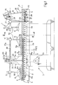
- Figure 1 shows a schematic side view, with parts removed for clarity, of a preferred embodiment of the forming machine according to the present invention;
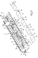
- Figure 2 shows a view in perspective, with parts removed for clarity, of part of the Figure 1 machine;
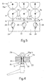
- Figure 3 shows a section, with parts removed for clarity, along line III-III in Figure 1;
- Figure 4 shows a larger-scale section along line IV-IV in Figure 1;
- Figure 5 shows a larger-scale side view of a detail in Figure 1;
- Figure 6 shows a larger-scale, partly sectioned view of a detail in Figures 1 and 3.
-
- Number 1 in Figures 1 and 2 indicates as a whole a forming machine for producing articles 2 of sheet material - in the example shown, flexible or presentation folders - from
flat blanks 2a (Figure 2). - As shown, particularly in Figure 1, machine 1 comprises a
base 3 supporting a poweredroller conveyor 4, in turn comprising two parallel, longitudinallateral shoulders 5 facing each other and separated transversely, and a number ofintermediate rollers 6 extending perpendicularly toshoulders 5.Rollers 6 are the same shape and size, are connected toshoulders 5 to rotate about respective fixedparallel axes 6a equally spaced with a spacing P, and are connected to a common synchronous poweredmechanical drive 7. - In the example described,
drive 7 is a chain drive, in which an electric motor 8 powers anendless chain 9 comprising atop drive branch 10 meshing with a number of identicaltoothed wheels 11, each fitted to one end of arelative roller 6, and abottom return branch 12, along which is fitted a known adjustable chain tensioning device 13 not described in detail (Figure 1). -
Roller conveyor 4 defines a support forblanks 2a, and cooperates with a number of known preloaded-idle-wheel pressure devices 15 located overconveyor 4, to feed, in use, an orderly succession ofblanks 2a along a straight forming path K (Figure 2) and through a number of work stations. -
Pressure devices 15 comprise a number of wheels rotating idly about respectiveparallel axes 15a separated by a spacing P1 equal to spacing P, and each located precisely at arespective roller 6.Devices 15 are connected to respective support assemblies 18 (Figures 1 and 3), each of which comprises a respective gantry-type frame 19, in turn comprising twouprights 20, preferably made of bent, welded sheet metal, and across member 21 separate fromuprights 20 and connected releasably to the ends ofuprights 20. - Each upright 20 extends upwards from a relative
lateral shoulder 5, and is connected toshoulder 5 by a respective locating and retainingassembly 22 forming part ofassembly 18 and comprising a respective row of locatingseats 24, which are formed in aplate portion 5a ofshoulder 5, with a spacing P2 equal to spacing P ofrollers 6, and are each located exactly beneath arespective roller 6. As shown, particularly in Figure 5, each locatingseat 24 is defined by a vertical slot symmetrical with respect to a relative vertical planeA containing axis 6a ofrelative roller 6 andaxis 15a of the corresponding idle wheels, if present. Each slot forms the bottom portion of a relative keyhole opening 26 (Figure 5), and each locatingassembly 22 also comprises two screw-nut screw ties 28 (Figures 1-4), each of which comprises a respective locating and lock screw 29 (Figure 4), the threadedshank 30 of which extends parallel toaxes 6a through a hole formed at the bottom end of relative upright 20, and through arelative slot 24, into which it is inserted by inserting itshead 30a through opening 26 (Figure 5) inportion 5a. The portion ofshank 30 projecting outwards of upright 20 is fitted with a nut 31, which cooperates withhead 30a to grip together upright 20 and the portion ofshoulder 5 definingslot 24. - As shown in Figures 1 and 3, each upright 20 terminates at the top with a respective fork, and
cross member 21 has twoopposite end portions portion 32 is hinged to the fork by a horizontal hinge pin 34'; andportion 33 is retained contacting relative upright 20 by a knowntoggle forcing device 34 on the outside of upright 20. The retaining action ofdevice 34 is opposed by acompression spring 34a gripped between a bottom stop surface of upright 20 andcross member 21, and which distances crossmember 21 fromroller conveyor 4 whendevice 34 is released. -
Cross member 21 is hung withrelative pressure devices 15, the position of which along path K and with respect toshoulders 5 is adjustable, as a function of the shape and size ofblanks 2a, by respective supporting and adjustingassemblies 35 forming part ofassembly 18. - Each
assembly 35 comprises a first and second guide and slide assembly, indicated 36 and 37, for adjusting said position along twoperpendicular axes axes 6a ofrollers 6 and the travelling direction K ofblanks 2a respectively. With reference to Figures 3 and 6,assembly 36 comprises a straight guide defined bycross member 21; and a slide defined by a substantially C-shaped, side-fit jaw 38 (Figure 6). More specifically,jaw 38 comprises abottom portion 39, alateral portion 40, and a top connectingportion 41, which together define aguide seat 42 engaged in sliding manner bycross member 21. Jaw 38 can be locked at any point alongcross member 21 by means of ascrew clamping device 43 comprising aplate 44 connected tolateral portion 40 to translate, under the control of a screw-nut screw assembly 45, between a lowered restposition allowing jaw 38 to move freely alongcross member 21 and/or release ofjaw 38 fromcross member 21, and a raised lock position in which it grips and locksjaw 38 and crossmember 21 together. -
Bottom portion 39 is hollow, and defines a throughseat 47 fitted through with a rod orbeam 48 parallel to travelling direction K and forming part ofsecond assembly 37 together withseat 47.Rod 48 can be positioned and locked insideseat 47 by means of a number ofscrews 49. - As shown in Figure 1 and particularly in Figure 3,
rod 48 is fitted withpressure devices 15, thevertical arms 50 of which are connected torod 48 byrespective jaws 51, which are shown schematically, are functionally similar tojaws 38, and mainly differ byrelative portions 40 being in the form ofportions 39 ofjaws 38, i.e. defining a vertical slideway forarm 50.Jaws 51 therefore provide for adjusting the height ofpressure devices 15 with respect toroller conveyor 4, and define, together withrespective rods 48, further guide and slide assemblies for adjusting the position ofpressure devices 15 parallel toaxis 37a. - With reference to Figure 2, in the example described, machine 1 also comprises a lateral deflecting and
folding coil 52, and a front fold-over device 53 (Figure 2), which, likepressure devices 15, are fitted torespective assemblies 35 connected tocross members 21 ofrelative frames 19. - With reference to Figure 2, fold-over
device 53 comprises anozzle 55 located beneathroller conveyor 4 and extending in the gap defined by twoconsecutive rollers 6 to emit a stream of compressed air; and acam 56 located overconveyor 4 and downstream fromnozzle 55 in the travelling direction ofblanks 2a. - By means of respective connecting devices similar to
devices 35,cross members 21 are also fitted with a gumming device 57 (Figure 2) located overroller conveyor 4, at a gap defined by twoconsecutive rollers 6, to deposit a bead of adhesive material onto a portion of the blank, and a number of conveniently through-beam-typeoptical devices 58 for detecting the presence or absence of a blank along forming path K. Likegumming device 57,optical devices 58 are also located overroller conveyor 4, each at a gap defined by twoconsecutive rollers 6. - In actual use, and as shown particularly in Figure 2, a blank 2a is fed to the input of
roller conveyor 4, and, by the rotation ofrollers 6 and the pressure exerted by afirst pressure device 15, is fed along path K through afolding station 60 equipped withcoil 52, which, as shown in Figure 2, is designed to fold a projectinglateral tab 61 inwards of blank 2a and onto an intermediate portion of the blank to produce asemifinished article 2b;semifinished article 2b is then fed through agumming station 62 where gummingdevice 57 deposits a bead B of adhesive material onto the foldedtab 61. Fromstation 62, the gummed semifinished article is fed to a further folding station 63 where a free end of afront tab 64 is first raised gradually offroller conveyor 4 by the stream of air fromnozzle 55, and is then turned backwards and over so that part offront tab 64 is superimposed onlateral tab 61, to which it is gummed by the adhesive material to form apocket 64. - As will be clear from the foregoing description, in machine 1 as described, by using a roller conveyor, by rotating the various rollers synchronously, and by positioning and maintaining the pressure devices in specific, stable reference positions along the whole of forming path K and with respect to
axes 6a ofrollers 6,blanks 2a are fed at all times along the same given feed path, thus eliminating all the problems caused, in known machines, by lateral slippage of the blanks/semifinished articles. In other words, by providing locating seats on bothshoulders 5 ofroller conveyor 4,pressure devices 15 can be positioned unequivocally, so that theaxes 15a of rotation of the idle pressure wheels are exactly parallel to theaxes 6a of rotation ofrollers 6, regardless of the position offrame 19 along forming path K. - Moreover, by connecting, not only the pressure devices, but also the folding, gumming, and detecting devices to respective gantry-
type frames 19 by means of continuous guide and slide adjusting assemblies, the above devices are positioned accurately, regardless of the size and shape of the input blanks. As regards the gumming and detecting devices in particular, these can each be located, as stated, at one of the gaps in the roller conveyor, so that any ill-dispensed adhesive material does not come into contact with the roller conveyor, and detection of the blanks/semifinished articles can be performed using any type of optical device either over or under the roller conveyor. - The presence of fixed gaps in the roller conveyor also allows the blanks to be worked on from underneath, thus simplifying the folding equipment over the roller conveyor and the folding operations in general.
- Finally, by connecting the cross members of the gantry-type frames releasably to the relative uprights, the pressure or folding or gumming devices can be withdrawn rapidly from the roller conveyor in the event of crumpling, incorrect folding or deformation of the blanks.
- Clearly, changes may be made to machine 1 as described herein without, however, departing from the scope of the present invention. In particular, correct positioning of the gantry-type frames with respect to the roller conveyor, and of said devices with respect to the gantry-type frames, may be achieved otherwise than as described by way of example. In particular, the gantry-type frames may be positioned using seats other than those shown, or other locating devices. Similarly, the roller drive, and the folding, detecting, and pressure devices may be formed otherwise than as described.
Claims (17)
- A forming machine (1) for producing articles (2) of sheet material from flat blanks (2a); the machine (1) comprising powered conveying means (4) for feeding an orderly succession of flat blanks (2a) along a forming path (K), and pressure means (15) for holding said blanks (2a) on the conveying means (4); and being characterized in that said conveying means comprise a roller conveyor (4) comprising two lateral shoulders (5), a number of intermediate rollers (6), each connected to the shoulders (5) to rotate about a respective axis (6a), and synchronous drive means (7) for rotating each of said rollers (6) about its axis (6a); said pressure means (15) being fitted to supporting means (18) comprising a supporting frame (19), and locating and retaining means (24, 28) associated with said shoulders (5) to locate and lock the supporting frame (19) along the forming path (K) in a number of fixed relative reference positions with respect to the shoulders (5).
- A machine as claimed in Claim 1, characterized by also comprising folding means (52) (53) for folding at least one portion (61) (64) of said blanks (2a); said folding means (52)(53) being carried by respective supporting means (18) identical with the supporting means of said pressure means (15).
- A machine as claimed in Claim 1 or 2, characterized in that said pressure means (15) comprise at least two revolving bodies rotating about respective parallel axes (15a); the axes (6a) of said rollers (6) being equally spaced with a first spacing (P), and the axes (15a) of said revolving bodies being equally spaced with a second spacing (P1) equal to said first spacing (P).
- A machine as claimed in Claim 3, characterized in that the vertical projection of each of said axes (15a) of said revolving bodies coincides with the axis (6a) of a corresponding said roller (6).
- A machine as claimed in any one of the foregoing Claims, characterized in that said locating and retaining means (24, 28) comprise, for each said shoulder (5), a row of retaining seats (24) spaced along said shoulder (5); the seats (24) being selectively engaged by a locating projection (30) carried by said frame (19); and releasable fat-fit gripping means (29, 31) being interposed between said shoulder (5) and said frame (19).
- A machine as claimed in Claim 5, characterized in that each said retaining seat (24) is symmetrical with respect to a vertical plane (A) containing said axes (6a) (15a).
- A machine as claimed in Claim 6, characterized in that each said shoulder (5) comprises a respective plate portion (5a); each said retaining seat (24) being defined by a slot formed through said plate portion (5a).
- A machine as claimed in Claim 7, characterized in that each said slot (24) forms part of a respective keyhole-shaped opening (26).
- A machine as claimed in one of Claims 5 to 8, characterized in that said fast-fit gripping means (29, 31) comprise, for each said frame (19), at least one respective threaded tie (29) carried by the frame (19); the tie comprising a shank (30) which engages said retaining seat (24), and a head (30a) resting on the shoulder (5); a nut (31) being screwed to the shank (30) to grip the frame (19) and a portion of said shoulder (5) together.
- A machine as claimed in any one of Claims 2 to 9, characterized in that said pressure means (15) and said folding means (52)(53) are fitted to respective said frames (19) by a respective first (36) and at least one respective second guide and slide assembly (37) to move independently of one another in two respective directions (36a)(37a) perpendicular to each other, and one of which is parallel to the axes (6a) of said rollers (6); locking means (43)(49) being associated with each guide and slide assembly to lock said pressure means (15) and said folding means (52)(53) releasably at any points over said roller conveyor (4).
- A machine as claimed in Claim 10, characterized in that each said second guide and slide assembly (37) comprises a slide defined by a beam (48) from which the relative pressure means (15)/folding means (52)(53) hang.
- A machine as claimed in Claim 11, characterized in that respective adjustable fastening means (51) are interposed between said beam (48) and said pressure means (15)/folding means (52)(53).
- A machine as claimed in one of Claims 10 to 12, characterized in that the slide of each said first guide and slide assembly comprises a C-shaped fastening jaw (38) which fits laterally to a cross member (21) of the relative said frame (19); screw locking means (43) being interposed between the fastening jaw (38) and said cross member (21).
- A machine as claimed in any one of the foregoing Claims, characterized in that each said frame (19) is a gantry-type frame, and comprises two uprights (20) connected to said shoulders (5), a cross member (21) separate from said uprights (20), and fast-fit connecting means (34, 34a) interposed between said cross member (21) and said uprights (20); said fast-fit connecting means (34, 34a) comprising retaining means (34), and elastic means (34a) acting in opposition to said retaining means (34) to move the cross member (21) away from the uprights (20) and from the roller conveyor (4).
- A machine as claimed in Claim 14, characterized in that said retaining means comprise a toggle locking device (34).
- A machine as claimed in any one of the foregoing Claims, characterized in that said synchronous drive means comprise a chain (9) powered by a single electric motor (8); and, for each of said rollers (6), a toothed wheel (11) fitted to the roller (6) and meshing with said chain (9).
- A machine as claimed in any one of the foregoing Claims, characterized by comprising a single angular position transducer (65) connected to one of said rollers (6).
Applications Claiming Priority (2)
| Application Number | Priority Date | Filing Date | Title |
|---|---|---|---|
| ITTO20021038 | 2002-11-29 | ||
| IT001038A ITTO20021038A1 (en) | 2002-11-29 | 2002-11-29 | FORMING MACHINE FOR THE REALIZATION OF ITEMS |
Publications (3)
| Publication Number | Publication Date |
|---|---|
| EP1424191A2 true EP1424191A2 (en) | 2004-06-02 |
| EP1424191A3 EP1424191A3 (en) | 2005-02-02 |
| EP1424191B1 EP1424191B1 (en) | 2009-04-15 |
Family
ID=32259987
Family Applications (1)
| Application Number | Title | Priority Date | Filing Date |
|---|---|---|---|
| EP03026901A Expired - Fee Related EP1424191B1 (en) | 2002-11-29 | 2003-11-24 | Forming machine for producing articles of sheet material from flat blanks |
Country Status (5)
| Country | Link |
|---|---|
| US (1) | US6981939B2 (en) |
| EP (1) | EP1424191B1 (en) |
| AT (1) | ATE428554T1 (en) |
| DE (2) | DE60327149D1 (en) |
| IT (1) | ITTO20021038A1 (en) |
Cited By (7)
| Publication number | Priority date | Publication date | Assignee | Title |
|---|---|---|---|---|
| US7544159B2 (en) * | 2006-11-24 | 2009-06-09 | Giorgio Petratto | Machine for producing articles of sheet material |
| DE102009023110A1 (en) | 2008-05-28 | 2009-12-03 | Giorgio Petratto | Blank alignment device for use in folding and pasting machine, has thrust component transferred to blanks, and blanks held in lateral contact with guiding surface, where component is arranged transverse to conveyor direction |
| US8061242B2 (en) | 2007-08-01 | 2011-11-22 | Kama Gmbh | Tool carrier device and apparatus for processing flat blanks |
| DE102011101740A1 (en) | 2010-05-14 | 2012-03-29 | Giorgio Petratto | Supplementary modular unit for production line for performs of sheet material and line, comprises master machines that are arranged in series, where conveyor is provided for advancing and displacing preforms along transport direction |
| DE102013006528A1 (en) | 2012-04-30 | 2013-10-31 | Giorgio Petratto | Carrier assembly for tools in folding and gluing machine for processing semi-finished sheet material for manufacture of e.g. bag, has bar and seat portion that are arranged to form closure, without any backlash in transport direction |
| DE102014012211A1 (en) * | 2014-08-16 | 2016-02-18 | Eisenmann Ag | Conveying device for transport structures |
| CN111497319A (en) * | 2020-06-04 | 2020-08-07 | 合肥柱石科技有限公司 | Material guiding and arranging mechanism |
Families Citing this family (6)
| Publication number | Priority date | Publication date | Assignee | Title |
|---|---|---|---|---|
| US9358727B2 (en) * | 2012-11-06 | 2016-06-07 | Miller Weldmaster Corporation | Dual roll fabric welding machine and method of operation |
| CN105516809B (en) * | 2015-12-14 | 2019-02-26 | 深圳Tcl数字技术有限公司 | The start control circuit and method of television set |
| CN109532119B (en) * | 2018-11-28 | 2020-10-13 | 孟庆平 | Corrugated container board's production conveyor |
| CN112551232A (en) * | 2020-12-02 | 2021-03-26 | 安徽力幕新材料科技有限公司 | Protective equipment for aluminum plate with foil |
| US20220373129A1 (en) * | 2021-05-20 | 2022-11-24 | John Powers, III | Arcuate mounting bracket and fabrication system |
| CN117125399B (en) * | 2023-10-27 | 2024-01-30 | 荣智工企智能技术(昆山)有限公司 | Full rubber coating pole piece cylinder conveyer of power battery |
Citations (3)
| Publication number | Priority date | Publication date | Assignee | Title |
|---|---|---|---|---|
| US5019026A (en) * | 1989-02-09 | 1991-05-28 | Bobst Sa | Device for aligning box blanks within a machine used for processing them |
| US5413327A (en) * | 1993-02-09 | 1995-05-09 | Bobst Sa | Device for aligning box blanks for a machine processing box blanks |
| CH689300A5 (en) * | 1993-09-30 | 1999-02-15 | Bobst Sa | Cardboard box folding and gluing machine |
Family Cites Families (8)
| Publication number | Priority date | Publication date | Assignee | Title |
|---|---|---|---|---|
| CH528374A (en) * | 1971-03-10 | 1972-09-30 | Mueller Hans Grapha Masch | Method and device for the production of books, brochures or booklets assembled from a large number of sheets of paper |
| US4419088A (en) * | 1981-06-19 | 1983-12-06 | Nemec David G | Gate folding apparatus |
| GB8729442D0 (en) * | 1987-12-17 | 1988-02-03 | Chambon Ltd | Carton blank die-cutting machine assembly |
| US4979933A (en) * | 1988-04-27 | 1990-12-25 | Kraft, Inc. | Reclosable bag |
| EP0612879B1 (en) * | 1993-02-18 | 1995-02-08 | Jensen Ag Burgdorf | Apparatus for the automatic folding of laundry |
| DE19814917C2 (en) * | 1998-04-03 | 2000-09-21 | Texpa Maschinenbau Gmbh & Co K | Plant for folding a textile web section |
| IT1316185B1 (en) * | 2000-01-24 | 2003-04-03 | Engico Srl | AUTOMATIC MACHINE FOR SLOTTING AND CORDING CARDBOARD SHEETS AND SIMILAR |
| US6612974B2 (en) * | 2001-02-01 | 2003-09-02 | Hallmark Cards Incorporated | Adjustable folding station for cards |
-
2002
- 2002-11-29 IT IT001038A patent/ITTO20021038A1/en unknown
-
2003
- 2003-11-24 DE DE60327149T patent/DE60327149D1/en not_active Expired - Lifetime
- 2003-11-24 DE DE20321704U patent/DE20321704U1/en not_active Expired - Lifetime
- 2003-11-24 AT AT03026901T patent/ATE428554T1/en not_active IP Right Cessation
- 2003-11-24 EP EP03026901A patent/EP1424191B1/en not_active Expired - Fee Related
- 2003-11-28 US US10/724,573 patent/US6981939B2/en not_active Expired - Lifetime
Patent Citations (3)
| Publication number | Priority date | Publication date | Assignee | Title |
|---|---|---|---|---|
| US5019026A (en) * | 1989-02-09 | 1991-05-28 | Bobst Sa | Device for aligning box blanks within a machine used for processing them |
| US5413327A (en) * | 1993-02-09 | 1995-05-09 | Bobst Sa | Device for aligning box blanks for a machine processing box blanks |
| CH689300A5 (en) * | 1993-09-30 | 1999-02-15 | Bobst Sa | Cardboard box folding and gluing machine |
Cited By (9)
| Publication number | Priority date | Publication date | Assignee | Title |
|---|---|---|---|---|
| US7544159B2 (en) * | 2006-11-24 | 2009-06-09 | Giorgio Petratto | Machine for producing articles of sheet material |
| US8061242B2 (en) | 2007-08-01 | 2011-11-22 | Kama Gmbh | Tool carrier device and apparatus for processing flat blanks |
| DE102009023110A1 (en) | 2008-05-28 | 2009-12-03 | Giorgio Petratto | Blank alignment device for use in folding and pasting machine, has thrust component transferred to blanks, and blanks held in lateral contact with guiding surface, where component is arranged transverse to conveyor direction |
| DE102011101740A1 (en) | 2010-05-14 | 2012-03-29 | Giorgio Petratto | Supplementary modular unit for production line for performs of sheet material and line, comprises master machines that are arranged in series, where conveyor is provided for advancing and displacing preforms along transport direction |
| DE102013006528A1 (en) | 2012-04-30 | 2013-10-31 | Giorgio Petratto | Carrier assembly for tools in folding and gluing machine for processing semi-finished sheet material for manufacture of e.g. bag, has bar and seat portion that are arranged to form closure, without any backlash in transport direction |
| DE102014012211A1 (en) * | 2014-08-16 | 2016-02-18 | Eisenmann Ag | Conveying device for transport structures |
| US10124958B2 (en) | 2014-08-16 | 2018-11-13 | Eisenmann Se | Conveyor device for transporation structures |
| CN111497319A (en) * | 2020-06-04 | 2020-08-07 | 合肥柱石科技有限公司 | Material guiding and arranging mechanism |
| CN111497319B (en) * | 2020-06-04 | 2021-02-23 | 合肥柱石科技有限公司 | Material guiding and arranging mechanism |
Also Published As
| Publication number | Publication date |
|---|---|
| EP1424191A3 (en) | 2005-02-02 |
| EP1424191B1 (en) | 2009-04-15 |
| US6981939B2 (en) | 2006-01-03 |
| ITTO20021038A1 (en) | 2004-05-30 |
| DE60327149D1 (en) | 2009-05-28 |
| US20040162204A1 (en) | 2004-08-19 |
| DE20321704U1 (en) | 2009-02-19 |
| ATE428554T1 (en) | 2009-05-15 |
Similar Documents
| Publication | Publication Date | Title |
|---|---|---|
| EP1424191B1 (en) | Forming machine for producing articles of sheet material from flat blanks | |
| US4704100A (en) | Bag making apparatus and method | |
| US7828708B2 (en) | Case erector and sealer apparatus | |
| KR100648870B1 (en) | Device for aligning plate-like workpieces in a machine processing them | |
| EP1818262B1 (en) | A unit for positioning a sheet of film to cover the tops of product groups | |
| DE4042178C2 (en) | Device for applying labels or the like to packages | |
| JPH02187327A (en) | Method and apparatus for fixing clip for machine for manufacturing envelope and equivalent | |
| DD213890A5 (en) | METHOD AND DEVICE FOR PRODUCING COLLECTOR PACKAGING | |
| AU2007262577B2 (en) | Device for machining continuously successively transported, flat objects or an almost endless web of material | |
| JP2000505749A (en) | Roller hold down device for carton with 4 side taper | |
| JP2010535142A (en) | Method and apparatus for forming a group of substantially parallelepiped objects moving on a conveyor belt | |
| IE913844A1 (en) | Carton Folding Apparatus | |
| AU2008281716B2 (en) | Tool carrier device and device for machining flat sections | |
| DE60224714T2 (en) | Process for packaging cigarettes in soft packs | |
| DE19955993A1 (en) | Book casing=in machine, includes book block conveyor with page splaying device, and transfer grab for for gripping blocks between splayed pages | |
| EP1707488B1 (en) | Adjustable infeed bed for packaging apparatus | |
| JPH034468B2 (en) | ||
| US10351355B2 (en) | Auto changeover infeed assembly | |
| WO2009121542A1 (en) | Device and method for producing bags from pieces of tubing | |
| CN210911380U (en) | Automatic embossing machine | |
| EP1818263A1 (en) | Method for packaging of goods and its use in a corresponding machine | |
| US3330715A (en) | Apparatus for applying adhesive patterns to flat cardboard elements | |
| EP1456085B1 (en) | Apparatus and method for handling a tobacco pouch-like packaging | |
| EP1002727A2 (en) | Assembly and conveyor apparatus, particularly for packaging system | |
| US20120035033A1 (en) | Device for supplying sheets |
Legal Events
| Date | Code | Title | Description |
|---|---|---|---|
| PUAI | Public reference made under article 153(3) epc to a published international application that has entered the european phase |
Free format text: ORIGINAL CODE: 0009012 |
|
| AK | Designated contracting states |
Kind code of ref document: A2 Designated state(s): AT BE BG CH CY CZ DE DK EE ES FI FR GB GR HU IE IT LI LU MC NL PT RO SE SI SK TR |
|
| AX | Request for extension of the european patent |
Extension state: AL LT LV MK |
|
| PUAL | Search report despatched |
Free format text: ORIGINAL CODE: 0009013 |
|
| AK | Designated contracting states |
Kind code of ref document: A3 Designated state(s): AT BE BG CH CY CZ DE DK EE ES FI FR GB GR HU IE IT LI LU MC NL PT RO SE SI SK TR |
|
| AX | Request for extension of the european patent |
Extension state: AL LT LV MK |
|
| RIC1 | Information provided on ipc code assigned before grant |
Ipc: 7B 31B 19/26 B Ipc: 7B 31B 1/04 A Ipc: 7B 31B 19/60 B Ipc: 7B 65H 29/12 B Ipc: 7B 65G 39/18 B |
|
| 17P | Request for examination filed |
Effective date: 20050727 |
|
| AKX | Designation fees paid |
Designated state(s): AT BE BG CH CY CZ DE DK EE ES FI FR GB GR HU IE IT LI LU MC NL PT RO SE SI SK TR |
|
| GRAP | Despatch of communication of intention to grant a patent |
Free format text: ORIGINAL CODE: EPIDOSNIGR1 |
|
| TPAC | Observations filed by third parties |
Free format text: ORIGINAL CODE: EPIDOSNTIPA |
|
| GRAS | Grant fee paid |
Free format text: ORIGINAL CODE: EPIDOSNIGR3 |
|
| GRAA | (expected) grant |
Free format text: ORIGINAL CODE: 0009210 |
|
| AK | Designated contracting states |
Kind code of ref document: B1 Designated state(s): AT BE BG CH CY CZ DE DK EE ES FI FR GB GR HU IE IT LI LU MC NL PT RO SE SI SK TR |
|
| REG | Reference to a national code |
Ref country code: CH Ref legal event code: EP Ref country code: GB Ref legal event code: FG4D |
|
| REG | Reference to a national code |
Ref country code: IE Ref legal event code: FG4D |
|
| REG | Reference to a national code |
Ref country code: CH Ref legal event code: NV Representative=s name: KELLER & PARTNER PATENTANWAELTE AG |
|
| REF | Corresponds to: |
Ref document number: 60327149 Country of ref document: DE Date of ref document: 20090528 Kind code of ref document: P |
|
| NLV1 | Nl: lapsed or annulled due to failure to fulfill the requirements of art. 29p and 29m of the patents act | ||
| PG25 | Lapsed in a contracting state [announced via postgrant information from national office to epo] |
Ref country code: ES Free format text: LAPSE BECAUSE OF FAILURE TO SUBMIT A TRANSLATION OF THE DESCRIPTION OR TO PAY THE FEE WITHIN THE PRESCRIBED TIME-LIMIT Effective date: 20090726 Ref country code: AT Free format text: LAPSE BECAUSE OF FAILURE TO SUBMIT A TRANSLATION OF THE DESCRIPTION OR TO PAY THE FEE WITHIN THE PRESCRIBED TIME-LIMIT Effective date: 20090415 Ref country code: PT Free format text: LAPSE BECAUSE OF FAILURE TO SUBMIT A TRANSLATION OF THE DESCRIPTION OR TO PAY THE FEE WITHIN THE PRESCRIBED TIME-LIMIT Effective date: 20090915 Ref country code: FI Free format text: LAPSE BECAUSE OF FAILURE TO SUBMIT A TRANSLATION OF THE DESCRIPTION OR TO PAY THE FEE WITHIN THE PRESCRIBED TIME-LIMIT Effective date: 20090415 |
|
| PG25 | Lapsed in a contracting state [announced via postgrant information from national office to epo] |
Ref country code: NL Free format text: LAPSE BECAUSE OF FAILURE TO SUBMIT A TRANSLATION OF THE DESCRIPTION OR TO PAY THE FEE WITHIN THE PRESCRIBED TIME-LIMIT Effective date: 20090415 Ref country code: SE Free format text: LAPSE BECAUSE OF FAILURE TO SUBMIT A TRANSLATION OF THE DESCRIPTION OR TO PAY THE FEE WITHIN THE PRESCRIBED TIME-LIMIT Effective date: 20090715 Ref country code: SI Free format text: LAPSE BECAUSE OF FAILURE TO SUBMIT A TRANSLATION OF THE DESCRIPTION OR TO PAY THE FEE WITHIN THE PRESCRIBED TIME-LIMIT Effective date: 20090415 |
|
| PLBI | Opposition filed |
Free format text: ORIGINAL CODE: 0009260 |
|
| PG25 | Lapsed in a contracting state [announced via postgrant information from national office to epo] |
Ref country code: EE Free format text: LAPSE BECAUSE OF FAILURE TO SUBMIT A TRANSLATION OF THE DESCRIPTION OR TO PAY THE FEE WITHIN THE PRESCRIBED TIME-LIMIT Effective date: 20090415 Ref country code: DK Free format text: LAPSE BECAUSE OF FAILURE TO SUBMIT A TRANSLATION OF THE DESCRIPTION OR TO PAY THE FEE WITHIN THE PRESCRIBED TIME-LIMIT Effective date: 20090415 Ref country code: CZ Free format text: LAPSE BECAUSE OF FAILURE TO SUBMIT A TRANSLATION OF THE DESCRIPTION OR TO PAY THE FEE WITHIN THE PRESCRIBED TIME-LIMIT Effective date: 20090415 Ref country code: RO Free format text: LAPSE BECAUSE OF FAILURE TO SUBMIT A TRANSLATION OF THE DESCRIPTION OR TO PAY THE FEE WITHIN THE PRESCRIBED TIME-LIMIT Effective date: 20090415 |
|
| PLAX | Notice of opposition and request to file observation + time limit sent |
Free format text: ORIGINAL CODE: EPIDOSNOBS2 |
|
| 26 | Opposition filed |
Opponent name: KAMA GMBH Effective date: 20100115 |
|
| PG25 | Lapsed in a contracting state [announced via postgrant information from national office to epo] |
Ref country code: SK Free format text: LAPSE BECAUSE OF FAILURE TO SUBMIT A TRANSLATION OF THE DESCRIPTION OR TO PAY THE FEE WITHIN THE PRESCRIBED TIME-LIMIT Effective date: 20090415 Ref country code: BE Free format text: LAPSE BECAUSE OF FAILURE TO SUBMIT A TRANSLATION OF THE DESCRIPTION OR TO PAY THE FEE WITHIN THE PRESCRIBED TIME-LIMIT Effective date: 20090415 |
|
| PG25 | Lapsed in a contracting state [announced via postgrant information from national office to epo] |
Ref country code: BG Free format text: LAPSE BECAUSE OF FAILURE TO SUBMIT A TRANSLATION OF THE DESCRIPTION OR TO PAY THE FEE WITHIN THE PRESCRIBED TIME-LIMIT Effective date: 20090715 |
|
| PLBB | Reply of patent proprietor to notice(s) of opposition received |
Free format text: ORIGINAL CODE: EPIDOSNOBS3 |
|
| PG25 | Lapsed in a contracting state [announced via postgrant information from national office to epo] |
Ref country code: MC Free format text: LAPSE BECAUSE OF NON-PAYMENT OF DUE FEES Effective date: 20091130 |
|
| REG | Reference to a national code |
Ref country code: IE Ref legal event code: MM4A |
|
| PG25 | Lapsed in a contracting state [announced via postgrant information from national office to epo] |
Ref country code: IE Free format text: LAPSE BECAUSE OF NON-PAYMENT OF DUE FEES Effective date: 20091124 Ref country code: GR Free format text: LAPSE BECAUSE OF FAILURE TO SUBMIT A TRANSLATION OF THE DESCRIPTION OR TO PAY THE FEE WITHIN THE PRESCRIBED TIME-LIMIT Effective date: 20090716 |
|
| PG25 | Lapsed in a contracting state [announced via postgrant information from national office to epo] |
Ref country code: IT Free format text: LAPSE BECAUSE OF FAILURE TO SUBMIT A TRANSLATION OF THE DESCRIPTION OR TO PAY THE FEE WITHIN THE PRESCRIBED TIME-LIMIT Effective date: 20090415 |
|
| PG25 | Lapsed in a contracting state [announced via postgrant information from national office to epo] |
Ref country code: LU Free format text: LAPSE BECAUSE OF NON-PAYMENT OF DUE FEES Effective date: 20091124 |
|
| PG25 | Lapsed in a contracting state [announced via postgrant information from national office to epo] |
Ref country code: HU Free format text: LAPSE BECAUSE OF FAILURE TO SUBMIT A TRANSLATION OF THE DESCRIPTION OR TO PAY THE FEE WITHIN THE PRESCRIBED TIME-LIMIT Effective date: 20091016 |
|
| PG25 | Lapsed in a contracting state [announced via postgrant information from national office to epo] |
Ref country code: TR Free format text: LAPSE BECAUSE OF FAILURE TO SUBMIT A TRANSLATION OF THE DESCRIPTION OR TO PAY THE FEE WITHIN THE PRESCRIBED TIME-LIMIT Effective date: 20090415 |
|
| PG25 | Lapsed in a contracting state [announced via postgrant information from national office to epo] |
Ref country code: CY Free format text: LAPSE BECAUSE OF FAILURE TO SUBMIT A TRANSLATION OF THE DESCRIPTION OR TO PAY THE FEE WITHIN THE PRESCRIBED TIME-LIMIT Effective date: 20090415 |
|
| PLCK | Communication despatched that opposition was rejected |
Free format text: ORIGINAL CODE: EPIDOSNREJ1 |
|
| PLBN | Opposition rejected |
Free format text: ORIGINAL CODE: 0009273 |
|
| STAA | Information on the status of an ep patent application or granted ep patent |
Free format text: STATUS: OPPOSITION REJECTED |
|
| 27O | Opposition rejected |
Effective date: 20130219 |
|
| REG | Reference to a national code |
Ref country code: DE Ref legal event code: R100 Ref document number: 60327149 Country of ref document: DE Effective date: 20130219 |
|
| REG | Reference to a national code |
Ref country code: CH Ref legal event code: PCAR Free format text: NEW ADDRESS: EIGERSTRASSE 2 POSTFACH, 3000 BERN 14 (CH) |
|
| REG | Reference to a national code |
Ref country code: FR Ref legal event code: PLFP Year of fee payment: 13 |
|
| REG | Reference to a national code |
Ref country code: FR Ref legal event code: PLFP Year of fee payment: 14 |
|
| REG | Reference to a national code |
Ref country code: DE Ref legal event code: R079 Ref document number: 60327149 Country of ref document: DE Free format text: PREVIOUS MAIN CLASS: B31B0001040000 Ipc: B31B0050040000 |
|
| REG | Reference to a national code |
Ref country code: FR Ref legal event code: PLFP Year of fee payment: 15 |
|
| REG | Reference to a national code |
Ref country code: CH Ref legal event code: PFA Owner name: PETRATTO S.R.L., IT Free format text: FORMER OWNER: PETRATTO S.R.L., IT |
|
| PGFP | Annual fee paid to national office [announced via postgrant information from national office to epo] |
Ref country code: CH Payment date: 20201123 Year of fee payment: 18 Ref country code: GB Payment date: 20201126 Year of fee payment: 18 Ref country code: FR Payment date: 20201126 Year of fee payment: 18 Ref country code: DE Payment date: 20201130 Year of fee payment: 18 |
|
| REG | Reference to a national code |
Ref country code: DE Ref legal event code: R119 Ref document number: 60327149 Country of ref document: DE |
|
| REG | Reference to a national code |
Ref country code: CH Ref legal event code: PL |
|
| GBPC | Gb: european patent ceased through non-payment of renewal fee |
Effective date: 20211124 |
|
| PG25 | Lapsed in a contracting state [announced via postgrant information from national office to epo] |
Ref country code: GB Free format text: LAPSE BECAUSE OF NON-PAYMENT OF DUE FEES Effective date: 20211124 Ref country code: DE Free format text: LAPSE BECAUSE OF NON-PAYMENT OF DUE FEES Effective date: 20220601 |
|
| PG25 | Lapsed in a contracting state [announced via postgrant information from national office to epo] |
Ref country code: FR Free format text: LAPSE BECAUSE OF NON-PAYMENT OF DUE FEES Effective date: 20211130 |
|
| PG25 | Lapsed in a contracting state [announced via postgrant information from national office to epo] |
Ref country code: LI Free format text: LAPSE BECAUSE OF NON-PAYMENT OF DUE FEES Effective date: 20220630 Ref country code: CH Free format text: LAPSE BECAUSE OF NON-PAYMENT OF DUE FEES Effective date: 20220630 |