EP1423666B1 - Waage mit niveaukompensationsfussbaugruppe - Google Patents
Waage mit niveaukompensationsfussbaugruppe Download PDFInfo
- Publication number
- EP1423666B1 EP1423666B1 EP02794660.7A EP02794660A EP1423666B1 EP 1423666 B1 EP1423666 B1 EP 1423666B1 EP 02794660 A EP02794660 A EP 02794660A EP 1423666 B1 EP1423666 B1 EP 1423666B1
- Authority
- EP
- European Patent Office
- Prior art keywords
- beams
- foot
- weighing scale
- base
- annular ring
- Prior art date
- Legal status (The legal status is an assumption and is not a legal conclusion. Google has not performed a legal analysis and makes no representation as to the accuracy of the status listed.)
- Expired - Lifetime
Links
- 238000005303 weighing Methods 0.000 title claims description 22
- 230000000712 assembly Effects 0.000 claims description 23
- 238000000429 assembly Methods 0.000 claims description 23
- 150000001875 compounds Chemical class 0.000 claims description 4
- 230000008878 coupling Effects 0.000 description 13
- 238000010168 coupling process Methods 0.000 description 13
- 238000005859 coupling reaction Methods 0.000 description 13
- 238000005452 bending Methods 0.000 description 10
- 239000002184 metal Substances 0.000 description 5
- 238000005259 measurement Methods 0.000 description 4
- 238000010276 construction Methods 0.000 description 3
- 230000003993 interaction Effects 0.000 description 3
- 239000004952 Polyamide Substances 0.000 description 2
- 230000002093 peripheral effect Effects 0.000 description 2
- 239000002985 plastic film Substances 0.000 description 2
- 229920002647 polyamide Polymers 0.000 description 2
- 229920000642 polymer Polymers 0.000 description 2
- 229920002554 vinyl polymer Polymers 0.000 description 2
- 239000004793 Polystyrene Substances 0.000 description 1
- 238000004026 adhesive bonding Methods 0.000 description 1
- 239000004020 conductor Substances 0.000 description 1
- 229920001577 copolymer Polymers 0.000 description 1
- 230000001419 dependent effect Effects 0.000 description 1
- 238000001746 injection moulding Methods 0.000 description 1
- 230000007246 mechanism Effects 0.000 description 1
- 239000000203 mixture Substances 0.000 description 1
- 230000004048 modification Effects 0.000 description 1
- 238000012986 modification Methods 0.000 description 1
- 229920000058 polyacrylate Polymers 0.000 description 1
- 229920000728 polyester Polymers 0.000 description 1
- 239000002861 polymer material Substances 0.000 description 1
- 229920000193 polymethacrylate Polymers 0.000 description 1
- 229920000098 polyolefin Polymers 0.000 description 1
- 229920002223 polystyrene Polymers 0.000 description 1
- 229920001021 polysulfide Polymers 0.000 description 1
- 239000005077 polysulfide Substances 0.000 description 1
- 150000008117 polysulfides Polymers 0.000 description 1
- 230000004044 response Effects 0.000 description 1
- 125000000391 vinyl group Chemical group [H]C([*])=C([H])[H] 0.000 description 1
Images




Classifications
-
- G—PHYSICS
- G01—MEASURING; TESTING
- G01G—WEIGHING
- G01G23/00—Auxiliary devices for weighing apparatus
- G01G23/002—Means for correcting for obliquity of mounting
-
- G—PHYSICS
- G01—MEASURING; TESTING
- G01G—WEIGHING
- G01G19/00—Weighing apparatus or methods adapted for special purposes not provided for in the preceding groups
- G01G19/44—Weighing apparatus or methods adapted for special purposes not provided for in the preceding groups for weighing persons
-
- Y—GENERAL TAGGING OF NEW TECHNOLOGICAL DEVELOPMENTS; GENERAL TAGGING OF CROSS-SECTIONAL TECHNOLOGIES SPANNING OVER SEVERAL SECTIONS OF THE IPC; TECHNICAL SUBJECTS COVERED BY FORMER USPC CROSS-REFERENCE ART COLLECTIONS [XRACs] AND DIGESTS
- Y10—TECHNICAL SUBJECTS COVERED BY FORMER USPC
- Y10S—TECHNICAL SUBJECTS COVERED BY FORMER USPC CROSS-REFERENCE ART COLLECTIONS [XRACs] AND DIGESTS
- Y10S177/00—Weighing scales
- Y10S177/09—Scale bearings
Definitions
- This invention relates generally to electronic type platform weighing systems, and more particularly to a free-standing scale having an improved base member for aligning parts of the scale.
- One popular type of electronic weighing scale is constructed with a platform for receiving the load to be weighed and a set of levers, pivots, flexures, and torque tubes to mechanically combine the forces applied to the platform by the load. The combined forces are then applied to a single electronic load cell to yield the weight of the load.
- the load cell is typically constructed with a mechanically-deformable sensor plate which operates as a force transducer.
- the sensor plate includes one or more sensor elements that serve to convert the mechanical bending forces of the sensor plate into electrical signals. When a load is applied to such a load cell, the sensor elements produce electrical signals which are proportional to the load applied to the load cell.
- Load cell measurement beams are typically either of two types, bending beams or shear beams. Bending beams undergo bending strains that vary as a function of the weight of the load applied to the beams, while shear beams undergo shear strains that vary as a function of the weight of the load applied to the beams. Strain measuring devices, such as strain gauges or the like, are normally mounted on the beams to measure the magnitude of the load induced bending strains in bending beams or the load induced shear strains in shear beams.
- the accuracy of load cells employing bending beams and shear beams is highly dependent on the manner in which the beams are supported and/or how the loads are coupled to the beams.
- changes in the load induced deformation of the beam i.e., the bending strain or shear strain, should be solely a function of changes in the weight of the load. If the structure that either supports the beam or couples the load to the beam applies rotational moments or twisting torques to the beam, then the deformation of the beam will not be a true indication of the weight of the load.
- the beam supporting or loading structure should not restrain the beam from the load induced deformations that are to be measured.
- the support structure should allow the ends of the beam to freely pivot.
- the location at which the beam is supported and/or the location where the load is applied to the beam can also affect the accuracy of load cells using measurement beams.
- a scale assembly that includes a platform which is supported by a plurality of force transmitting assemblies.
- the force transmitting assemblies and platform cooperate to automatically center the platform relative to an enclosing structure and to align the force transmitting assemblies and platform.
- the automatic centering of the platform and aligning of the force transmitting assemblies is accomplished by moving the platform back and forth in sideways directions against stops which limit motion of the platform. Centering the platform and aligning the force transmitting assemblies is claimed to be effective to eliminate sideward force components on load cells.
- a portable load scale for use in rugged terrain or at locations without suitable support pads.
- the load scale includes a support deck affixed to a base platform through a plural number of load cells.
- the base platform is constructed to provide ramp members joined by longitudinal runner assemblies to form a rigid, non-flexing assembly having a central gap and gaps between pairs of ramp members to reduce the standard rectangular footprint by approximately thirty percent.
- the runner assemblies are constructed so that the bottom of the support deck is separated from the top of the base plate of the runner assemblies by a distance of several inches.
- the load cells are mounted onto the underside of the support deck and joined to the base platform by ball bushings such that the load cells can pivot in any or about all axis directions relative to the base platform to relieve stresses induced by uneven terrain.
- a foot assembly for a weighing scale including a base having a cylindrical wall, an annular ring arranged in coaxial spaced relation to the base, and supported by a plurality of resilient compensation beams that project radially outwardly from a portion of the base;
- Each of the resilient beams comprises a compound curve contour having a plurality of curved sections each defined by respective separate and spaced apart centres to form an 'S' shape, so that the plurality of resilient beams may twist and/or bend so as to take up and compensate for the resultant unwanted rotational moments or twisting torques that result from placement of the foot assembly on an uneven surface. resultant unwanted rotational moments or twisting torques that result from placement of the foot assembly on an uneven surface.
- a weighing scale including a platform coupled to a mounting tray, where the mounting tray has a plurality of apertures.
- a weight determination assembly is positioned between the platform and the mounting tray.
- a plurality of force transfer beams are arranged within the mounting tray so as to substantially support the platform and the mounting tray such that the mounting tray is isolated from a support surface. In this way, forces that are applied to the weighing scale by the placement of a load on the platform are transferred to the plurality of force transfer beams, without direct interaction between the mounting tray and the support surface.
- a plurality of foot assemblies are positioned within the apertures and operatively interconnected to the plurality of force transfer beams.
- Each of the foot assemblies includes a base having a plurality of compensation beams that project radially outwardly so as to support an annular ring that is coupled to the mounting tray. In this way, if a support surface onto which the weighing scale is placed is canted at some angle, the compensation beams twist and/or bend so as to take up and compensate for any unwanted rotational moments or twisting torques.
- a scale 10 formed in accordance with the present invention includes a platform 12, a mounting tray 14, a force transfer assembly 16, a weight determination assembly 18, and a display 20. More particularly, platform 12 is sized and shaped so as to be positioned in overlying relation to mounting tray 14. Platform 12 and mounting tray 14 are often rectilinearly shaped, and are normally formed from either metal or a stiff polymer. Other shapes are also possible for use with the present invention. Platform 12 and mounting tray 14 are coupled to one another along a peripheral edge 21 in a conventional manner, e.g., mechanical fasteners, welds, adhesive bonding, or the like. A receiving surface of platform 12, upon which a load may be placed, is often covered by a vinyl or plastic sheet 23 so as to provide a non-slip surface.
- Mounting tray 14 is typically molded from a suitable engineering polymer, or formed (i.e., stamped or drawn from a suitable metal sheet) so as to have an annular wall 24 supporting peripheral edge 21, and surrounding a central, channeled surface 25 ( Fig. 2 ).
- a plurality of apertures 27 are defined through portions of central surface 25 in spaced apart relation to one another. For example, when scale 10 comprises a rectilinear shape, apertures 27 are located in the corners of mounting tray 14.
- a vertically oriented slot 30 is defined within the portion of wall 24 that is adjacent to a respective one of each of plurality of apertures 27.
- a plurality of recessed channels 29 are also formed in central surface 25 of mounting tray 14. Plurality of recessed channels 29 are sized and arranged in central surface 25 so as to receive and locate portions of force transfer assembly 16, weight determination assembly 18, and display 20.
- force transfer assembly 16 includes a pair of primary beams 36, a pair of secondary beams 38, and a plurality of foot assemblies 40. More particularly, each primary beam 36 is formed from a substantially flat strip of metal often having a length that is larger than its width, and a width that is larger than its thickness, e.g. a thin, elongate plate.
- Primary beams 36 each include a foot engagement end 42 and a sensor engagement end 44.
- Each foot engagement end 42 includes a substantially "V" shaped pier-notch 48, a substantially "V” shaped tray-notch 50, a cam lock 51 and at least one platform support pad 52 ( Figs. 3 and 4 ).
- Pier-notch 48 and tray-notch 50 open onto different edges of foot engagement end 42.
- Primary beams 36 are arranged within channels 29 of central surface 25 such that sensor engagement ends 44 are located adjacent to one another and to weight determination assembly 18 ( Fig. 2 ). Each sensor engagement end 44 is adapted to operatively engage a portion of weight determination assembly 18.
- foot engagement ends 42 are positioned in spaced apart relation to one another, and each overtop of a respective aperture 27.
- a coupling hole 57 is defined through a portion of each primary beam 36 in spaced relation to both foot engagement end 42 and sensor engagement end 44.
- Secondary beams 38 are also formed from a substantially flat strip of metal having a length that is larger than its width, and a width that is larger than its thickness, e.g. a thin, elongate plate.
- Each secondary beam 38 includes a foot engagement end 62 and a coupling end 64.
- Secondary beams 38 are generally shorter than primary beams 36, and are arranged within channels 29 of central surface 25 such that coupling ends 64 are located within coupling hole 57 of an adjacent primary beam 36.
- Each foot engagement end 62 includes a substantially "V” shaped pier-notch notch 68, a substantially “V” shaped tray-notch 70, a cam lock 71 and a pair of platform support pads 72a,72b ( Figs. 5 and 6 ).
- Each coupling end 64 is sized and shaped to be received within coupling hole 57 of an adjacent primary beam 36.
- a biasing spring 77 is positioned on central surface 25 directly below each secondary beam 38 so as to bias each coupling end 64 against a portion of the interior surface of primary beam 36 that defines coupling hole 57.
- foot engagement ends 62 are positioned in spaced apart relation to one another, and each overtop of a respective aperture 27.
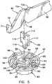
- each foot assembly 40 includes a base 80, an annular clamp-ring 82, a plurality of resilient beams 84, and a pier 86. More particularly, base 80, annular clamp-ring 82, and beams 84 are preferably formed as an integral unit (e.g., by injection molding) from one of the well known polymer materials that are suitable for use in structures requiring mechanical strength and integrity, e.g., polyhalo-olefins, polyamides, polyolefins, polystyrenes, polyvinyls, polyacrylates, polymethacrylates, polyesters, polydienes, polyoxides, polyamides and polysulfides and their blends, copolymers and substituted derivatives thereof.
- polyhalo-olefins polyamides, polyolefins, polystyrenes, polyvinyls
- polyacrylates polymethacrylates
- polyesters polydienes
- polyoxides polyamides and polysulfides and their blend
- Base 80 often comprises a cylinder defined by a cylindrical wall 90 having a partial top wall 92 and central blind openings 94,95 ( Figs. 3 and 7 ).
- Annular clamp-ring 82 is arranged in coaxial spaced relation to a top portion 93 of cylindrical wall 90, and includes at least two through-holes 96 and at least two recesses 98 that are arranged in circumferentially spaced relation to one another, e.g., at 90° intervals around the circumference of the annular ring.
- Plurality of resilient beams 84 are arranged in circumferentially spaced relation to one another, e.g., at 90° intervals around the circumference of annular clamp-ring 82.
- Each beam 84 has a first end 100 that is fixedly clamped (e.g., integrally molded, or the like) to top portion 93 of cylindrical wall 90 and a second end 102 that is fixedly clamped to an inner surface 99 of annular clamp-ring 82. In this way, each beam 84 projects radially outwardly or away from top portion 93.
- each second end 102 is fixedly clamped at a location on inner surface 99 of annular clamp-ring 82 that is circumferentially spaced away from the location on top portion 93 of cylindrical wall 90 at which first end 100 is fixedly clamped to top portion 93 of base 80.
- the locations on annular clamp-ring 82 at which each second end 102 is fixedly clamped to inner surface 99 correspond to either one of through-holes 96 or one of recesses 98.
- resilient beams 84 often have a compound curve contour, i.e., having curved sections defined by separate and spaced apart centers, e.g., as in the letter "S" or the mathematical symbol for an integral sign " ⁇ ".
- beam 84 having a compound curve contour is preferable, other shapes and profiles of beam are possible for use with the present invention.
- it is the combination of the resilient spring properties of beams 84 and the transversely off-set positioning of their fixed first and second ends that provides for a high degree of compensation when unwanted rotational moments and twisting torques are applied to foot assemblies 40.
- pier 86 is preferably formed from a metal, and includes a leg 110 that projects downwardly from a plate 112.
- a central slot 114 is defined in plate 112, with knife-edge support 116 formed in plate 112 at the bottom of slot 114.
- a pad 120 is often positioned within blind opening 95 of base 80 in coaxially aligned relation to leg 110 so as to provide for a non-slip engagement with a support surface 125 ( Figs. 6-8 ).
- weight determination assembly 18 and display 20 are of the type often used in the weighing scale arts.
- the load cell having a bossed sensor plate taught in U.S. Patent No. 6,417,466 hereby incorporated herein by reference, provides a weight determination assembly 18 that is adequate for use with the present invention.
- a weight determination assembly includes a sensor plate for use in a load cell comprising a planar first surface, a planar second surface opposite the first surface which includes a depression formed therein defiling a flexure area.
- a load cavity is formed in the second surface having a conical receptacle end for receiving a strut.
- Sensors 126 are disposed over the flexure area for generating a signal in response to a load applied to the loading cavity, via interaction with sensor engagement ends 44 of primary beams 36.
- the signal is communicated to display 20 via conductors 127.
- the strut has a first conical projection end coupled to the conical receptacle end of the loading cavity and a second end coupled to a foot member such that the strut mechanically floats therebetween for providing the applied load at a substantially central position at the load cavity.
- Weight determination assembly 18 may be mounted on a channel support 128 forming part of mounting tray 14.
- Display 20 may comprise a known mechanical, electromechanical or electronic numerical display panel of the types that are well known in the art for presenting analog or digital numerical data, e.g., a rotary dial, LED, or LCD panels or the like.
- Scale 10 is assembled and functions in the following manner.
- Each foot assembly 40 is first positioned for placement within mounting tray 14 such that base 80 is arranged in confronting coaxially relation with an aperture 27. Once in this position, base 80 is moved toward and into aperture 27 until annular clamp-ring 82 engages the portion of central surface 25 that defines the perimeter of aperture 27. As this occurs, mounting studs 140 slip into each of through-holes 96. Mounting studs 140 are then bent over thereby clamping annular clamp-ring 82 securely to mounting tray 14. As a result of this construction, recesses 98 are arranged in parallel aligned relation to slot 30.
- a pier 86 may be positioned within each foot assembly 40 by positioning leg 110 in confronting coaxial relation with central blind opening 94. Pier 86 is then moved toward base 80 until leg 110 engages the bottom of central blind opening 94. In this position, slot 114 is arranged in parallel aligned relation with slot 30 in wall 24 and recesses 98 in annular clamp-ring 82.
- Force transfer assembly 16 is assembled to foot assemblies 40 and mounting tray 14 by first inserting each coupling end 64 of each secondary beam 38 into it's corresponding coupling hole 57 of a primary beam 36. Once in this position, the combined primary and secondary beams are arranged in spaced confronting relation to channels 29 such that foot engagement ends 42 and 62 are positioned in confronting relation to piers 86 of foot assemblies 40 ( Figs. 3 and 5 ). Once in this position, primary and secondary beams 36,38 are moved toward foot assemblies 40 such that pier-notches 48,68 enter slots 114 of piers 86, while at the same time, cam locks 51,71 enter slots 30 in wall 24 of mounting tray 14. When pier-notches 48,68 fully engage knife-edge 116 of piers 86, tray-notches 50,70 are seated against the edge of wall 24 that defines the terminal edge of each slot 30.
- mounting tray 14 is isolated from support surface 125 via foot assemblies 40 and foot engagement ends 42,62.
- mounting tray 14 is supported by the engagement of tray-notches 50,70 with the edge of wall 24 that defines the terminal edge of each slot 30.
- Primary beams 36 and secondary beams 38 are in turn supported upon each knife-edge 116 located within pier-notches 86.
- mounting tray 14 is isolated from support surface 125, i.e., it does not directly contact support surface 125. In this way, forces applied to weighing scale 10 by the placement of a load on platform 12 are transferred to force transfer assembly 16, via foot assemblies 40, without direction interaction between the underside of mounting tray 14 and support surface 125.
- platform 12 may be secured to mounting tray 14 such that a portion of the underside of platform 12 engages each of platform support pads 52 and 72a or 72b.
Landscapes
- Physics & Mathematics (AREA)
- General Physics & Mathematics (AREA)
- Measurement Of Force In General (AREA)
- Vibration Prevention Devices (AREA)
- Joining Of Building Structures In Genera (AREA)
- Weight Measurement For Supplying Or Discharging Of Specified Amounts Of Material (AREA)
Claims (10)
- Fußbaugruppe (40) für eine Waage (10), umfassend:eine Basis (80) mit einer zylindrischen Wand (90);einen ringförmigen Ring (82), der in koaxial beabstandeter Beziehung zu der Basis angeordnet ist; und mehrere elastische Balken (84), die nach außen aus einem Abschnitt (93) der Basis vorstehen, um den ringförmigen Ring zu tragen, dadurch gekennzeichnet, dassjeder der mehrere Balken eine "S"-förmige zusammengesetzte Kurvenkontur mit mehreren gekrümmten Abschnitten umfasst, die jeweils von zugehörigen separaten und beabstandeten Mitten definiert werden.
- Fußbaugruppe nach Anspruch 1, wobei der ringförmige Ring mindestens zwei Durchgangslöcher (96) und mindestens zwei Vertiefungen (98) aufweist, die in Umfangsrichtung beabstandet voneinander angeordnet sind.
- Fußbaugruppe nach einem der Ansprüche 1 oder 2, wobei jeder Balken ein erstes Ende (100), das fest mit der Basis eingespannt ist und ein zweites Ende (102) aufweist, das mit dem ringförmigen Ring fest eingespannt ist, sodass sich jedes zweite Ende an einer Stelle auf dem ringförmigen Ring befindet, die im Umfang von der Stelle auf der Basis beabstandet ist, an der das erste Ende fest eingespannt ist.
- Fußbaugruppe nach Anspruch 3, wobei die Stellen auf dem ringförmigen Ring, an dem jedes zweite Ende fest eingespannt ist, mindestens einem Durchgangsloch oder einer Vertiefung entsprechen.
- Fußbaugruppe nach einem der vorstehenden Ansprüche, wobei die Basis mindestens eine Sacköffnung (94), die zum Aufnehmen eines Abschnitts eines Stützpfeilers (86) bemessen ist, der einen Schenkel (110) aufweist, der sich nach unten von einer Platte (112) erstreckt, und einen Schlitz (114), der in der Platte definiert ist und in einem Schneidenlager (116) endet, aufweist.
- Waage (10), umfassend:mehrere Fußbaugruppen nach Anspruch 1; eine Plattform (12), die mit einer Montageplatte (14) gekoppelt ist, wobei die Montageplatte mehrere Öffnungen (27) aufweist;mehrere Kraftübertragungsbalken (36, 38); undmehrere Fußbaugruppen (40), die innerhalb der Öffnungen angeordnet sind und betriebswirksam mit den mehreren Kraftübertragungsbalken verbunden sind, wobei der Ring (82) jeder der mehreren Fußbaugruppen mit der Montageplatte gekoppelt ist.
- Waage nach Anspruch 6, wobei die mehreren elastischen Balken (84) in Umfangsrichtung voneinander beabstandet um den Umfang des ringförmigen Rings angeordnet sind.
- Waage nach einem der Ansprüche 6 und 7, wobei der das Schneidenlager (116) mindestens einen der Kraftübertragungsbalken trägt.
- Waage nach Anspruch 6, wobei die Montageplatte einen Abschnitt mit einem erhöhten Umfang aufweist, der in die untere Oberfläche der Plattform eingreift.
- Waage nach einem der Ansprüche 6 bis 9, wobei die Montageplatte mehrere Schlitze zur Aufnahme von zugehörigen Enden der Kraftübertragungsbalken aufweist.
Applications Claiming Priority (3)
| Application Number | Priority Date | Filing Date | Title |
|---|---|---|---|
| US31026301P | 2001-08-06 | 2001-08-06 | |
| US310263P | 2001-08-06 | ||
| PCT/US2002/024767 WO2003014676A2 (en) | 2001-08-06 | 2002-08-06 | Weighing scale with level compensating foot assembly |
Publications (3)
| Publication Number | Publication Date |
|---|---|
| EP1423666A2 EP1423666A2 (de) | 2004-06-02 |
| EP1423666A4 EP1423666A4 (de) | 2008-12-03 |
| EP1423666B1 true EP1423666B1 (de) | 2016-04-27 |
Family
ID=23201695
Family Applications (1)
| Application Number | Title | Priority Date | Filing Date |
|---|---|---|---|
| EP02794660.7A Expired - Lifetime EP1423666B1 (de) | 2001-08-06 | 2002-08-06 | Waage mit niveaukompensationsfussbaugruppe |
Country Status (5)
| Country | Link |
|---|---|
| US (2) | US6639158B2 (de) |
| EP (1) | EP1423666B1 (de) |
| CN (1) | CN1302266C (de) |
| AU (1) | AU2002332462A1 (de) |
| WO (1) | WO2003014676A2 (de) |
Families Citing this family (22)
| Publication number | Priority date | Publication date | Assignee | Title |
|---|---|---|---|---|
| US7151232B2 (en) * | 2002-08-06 | 2006-12-19 | Measurement Ltd. | Weighing scale with level compensating foot assembly |
| USD490007S1 (en) | 2003-02-18 | 2004-05-18 | Matsushita Electric Industrial Co., Ltd. | Combined body fat scale and weight scale |
| FR2852101B1 (fr) * | 2003-03-06 | 2006-11-24 | Pese-personne | |
| US7235746B2 (en) * | 2005-03-09 | 2007-06-26 | Metro Corporation | Modular apparatus for electronic scales and a method for assembling same |
| US7214892B2 (en) * | 2005-03-15 | 2007-05-08 | Metro Corporation | Scale lever assembly |
| US7989714B2 (en) * | 2007-10-05 | 2011-08-02 | Neopost Technologies | High capacity and high resolution scale |
| US7569779B2 (en) * | 2007-10-05 | 2009-08-04 | Neopost Technologies | High capacity and high resolution scale |
| DE102008029901B4 (de) * | 2008-06-24 | 2010-10-28 | Ika-Werke Gmbh & Co. Kg | Magnetrührer mit Aufstellfüßen |
| TWM344703U (en) * | 2008-07-03 | 2008-11-11 | Gemtek Technology Co Ltd | Bearing structure |
| DE102010022440A1 (de) * | 2010-05-28 | 2011-12-01 | Seca Ag | Vorrichtung zum Wiegen |
| US9494459B2 (en) * | 2014-11-30 | 2016-11-15 | Portal 724, LLC | Self-leveling scale |
| PL414679A1 (pl) * | 2015-11-04 | 2017-05-08 | Megaterm Plus Spółka Z Ograniczoną Odpowiedzialnością | Polimerowa płyta pomiarowa platformy wagowej i sposób wytwarzania polimerowej płyty pomiarowej platformy wagowej |
| CN106323436A (zh) * | 2016-08-13 | 2017-01-11 | 深圳市前海安测信息技术有限公司 | 自动调节水平度的健康一体机 |
| JP6565959B2 (ja) * | 2017-03-07 | 2019-08-28 | ヤマハ株式会社 | 電子機器用支持脚及び電子機器 |
| JP6767494B2 (ja) | 2017-03-31 | 2020-10-14 | 佛山市▲順▼▲徳▼区美的▲電▼▲熱▼▲電▼器制造有限公司Foshan Shunde Midea Electrical Heating Appliances Manufacturing Co., Ltd. | 分離式炊飯器 |
| IT201700115209A1 (it) * | 2017-10-12 | 2019-04-12 | Chep Deutschland Gmbh | Sistema di pallet e componente di misura |
| CN108143421B (zh) * | 2017-12-21 | 2024-07-19 | 西安蒜泥电子科技有限责任公司 | 一种人体三维扫描人体成分检测装置 |
| CN108433703B (zh) * | 2018-04-10 | 2023-09-15 | 西安维塑智能科技有限公司 | 一种三维人体扫描设备 |
| US11892340B2 (en) * | 2020-02-28 | 2024-02-06 | Honeywell International Inc. | Weight scale with centralized lever supported receiving tray |
| US11262231B1 (en) * | 2020-05-29 | 2022-03-01 | Bertec Corporation | Swivel foot assembly for a force plate or balance plate |
| EP4080176B1 (de) * | 2021-04-19 | 2023-06-28 | seca gmbh & co. kg | Waage mit einer messplattform, die von standfüssen getragen wird |
| CN115307712B (zh) * | 2022-09-16 | 2025-02-28 | 深圳市伊欧乐科技有限公司 | 一种秤脚的导正吸附装置 |
Citations (1)
| Publication number | Priority date | Publication date | Assignee | Title |
|---|---|---|---|---|
| EP0984251A2 (de) * | 1998-09-03 | 2000-03-08 | Measurement Specialties, Inc. | Wägezelle mit Buckelsensorscheibe für eine Auswägeeinrichtung von elektrischen Wägeanalagen |
Family Cites Families (17)
| Publication number | Priority date | Publication date | Assignee | Title |
|---|---|---|---|---|
| US4458771A (en) * | 1982-09-20 | 1984-07-10 | Tricolor Corporation | Corner post mount for weighing scale |
| US4554987A (en) | 1983-08-29 | 1985-11-26 | Dillon Benny N | Self-aligning scale assembly and method |
| US4519464A (en) * | 1983-09-23 | 1985-05-28 | Malvern Scale Company | Weighing scale with adjustable suspension and thermal compensation |
| IL84998A (en) * | 1987-12-31 | 1990-01-18 | Keter Plastic Ltd | Platform type weighing scale |
| US4832142A (en) | 1988-04-11 | 1989-05-23 | Measurement Specialties, Inc. | Electronic scale apparatus |
| US5119896A (en) * | 1990-07-11 | 1992-06-09 | Pitney Bowes Inc. | Load cell supporting member and weighing scale incorporating the same |
| US5141065A (en) | 1990-11-14 | 1992-08-25 | Metro Corporation | Weight activated platform scale |
| SE468023B (sv) * | 1991-02-25 | 1992-10-19 | Asea Brown Boveri | Lastcellshus med inbyggd kraftgivare |
| CH682108A5 (de) * | 1991-04-30 | 1993-07-15 | Mettler Toledo Ag | |
| DK94293D0 (da) * | 1993-08-18 | 1993-08-18 | Scanvaegt As | Stoettefod, navnlig til understoetning af vejeceller i gulvstoettede vejeapparater |
| US5653417A (en) * | 1994-07-18 | 1997-08-05 | Pitney Bowes Inc. | Scale locking foot |
| DE19625821C1 (de) * | 1996-06-28 | 1997-12-18 | Johannes Borngaesser | Standfuß für eine Meßzelle |
| CN2293814Y (zh) * | 1996-11-24 | 1998-10-07 | 济南金钟电子衡器股份有限公司 | 电子皮带秤用橡胶耳轴支座 |
| US5894112A (en) | 1997-06-26 | 1999-04-13 | Intercomp Company | Weighing scale apparatus |
| GB9902403D0 (en) | 1999-02-03 | 1999-03-24 | Hanson Ind Ltd | A platform scale |
| US6177638B1 (en) | 2000-01-13 | 2001-01-23 | Clifford K. Murray | Portable load scale for uneven terrain |
| US6407351B1 (en) * | 1999-09-29 | 2002-06-18 | Premark Feg L.L.C. | Thread covering assembly for adjustable support feet and the like |
-
2002
- 2002-08-06 AU AU2002332462A patent/AU2002332462A1/en not_active Abandoned
- 2002-08-06 EP EP02794660.7A patent/EP1423666B1/de not_active Expired - Lifetime
- 2002-08-06 WO PCT/US2002/024767 patent/WO2003014676A2/en not_active Ceased
- 2002-08-06 CN CNB028182766A patent/CN1302266C/zh not_active Expired - Fee Related
- 2002-08-06 US US10/213,289 patent/US6639158B2/en not_active Expired - Lifetime
-
2003
- 2003-10-28 US US10/695,216 patent/US6936776B2/en not_active Expired - Fee Related
Patent Citations (1)
| Publication number | Priority date | Publication date | Assignee | Title |
|---|---|---|---|---|
| EP0984251A2 (de) * | 1998-09-03 | 2000-03-08 | Measurement Specialties, Inc. | Wägezelle mit Buckelsensorscheibe für eine Auswägeeinrichtung von elektrischen Wägeanalagen |
Also Published As
| Publication number | Publication date |
|---|---|
| WO2003014676A2 (en) | 2003-02-20 |
| US6936776B2 (en) | 2005-08-30 |
| US6639158B2 (en) | 2003-10-28 |
| US20040084227A1 (en) | 2004-05-06 |
| EP1423666A2 (de) | 2004-06-02 |
| WO2003014676A3 (en) | 2003-07-31 |
| US20030066690A1 (en) | 2003-04-10 |
| CN1555483A (zh) | 2004-12-15 |
| CN1302266C (zh) | 2007-02-28 |
| EP1423666A4 (de) | 2008-12-03 |
| AU2002332462A1 (en) | 2003-02-24 |
Similar Documents
| Publication | Publication Date | Title |
|---|---|---|
| US6639158B2 (en) | Weighing scale with level compensating foot assembly | |
| EP0984251B1 (de) | Wägezelle mit Buckelsensorscheibe für eine Auswägeeinrichtung von elektrischen Wägeanalagen | |
| US5510581A (en) | Mass-produced flat multiple-beam load cell and scales incorporating it | |
| US7151232B2 (en) | Weighing scale with level compensating foot assembly | |
| US4433741A (en) | Strain gage scale | |
| US4546838A (en) | Flexure isolated shear web load cell | |
| US4125168A (en) | Load cells for flexure isolated electronic scale | |
| US4813504A (en) | Load cell structure | |
| US5447074A (en) | Strain gauge transducer force or weight measurement arrangement and touch tablet | |
| EP3194912B1 (de) | Flache wägezellenanordnung | |
| US4714121A (en) | Wheel scale assembly | |
| US4088015A (en) | Force measuring apparatus with mounting arrangement | |
| EP0978714A3 (de) | Lastzelle | |
| US4726436A (en) | Measuring equipment | |
| WO2000075617A1 (en) | Load cell | |
| EP1275943B1 (de) | Gerät zum Wiegen einer Ladung | |
| CA2071223C (en) | Mass-produced flat one-piece load cell and scales incorporating it | |
| JPH11211543A (ja) | ロードセルの過負荷防止装置 | |
| KR100317841B1 (ko) | 전자저울용로드셀및플랫폼 | |
| KR20010024325A (ko) | 계량저율 | |
| CN220366897U (zh) | 地毯秤 | |
| JP2654513B2 (ja) | ロードセル | |
| RU2058537C1 (ru) | Взвешивающее устройство | |
| JPH02234028A (ja) | ロードセル秤 | |
| JPH0129544Y2 (de) |
Legal Events
| Date | Code | Title | Description |
|---|---|---|---|
| PUAI | Public reference made under article 153(3) epc to a published international application that has entered the european phase |
Free format text: ORIGINAL CODE: 0009012 |
|
| 17P | Request for examination filed |
Effective date: 20040218 |
|
| AK | Designated contracting states |
Kind code of ref document: A2 Designated state(s): AT BE BG CH CY CZ DE DK EE ES FI FR GB GR IE IT LI LU MC NL PT SE SK TR |
|
| AX | Request for extension of the european patent |
Extension state: AL LT LV MK RO SI |
|
| A4 | Supplementary search report drawn up and despatched |
Effective date: 20081105 |
|
| RIC1 | Information provided on ipc code assigned before grant |
Ipc: G01G 23/00 20060101ALI20081030BHEP Ipc: G01G 19/44 20060101ALI20081030BHEP Ipc: G01G 21/08 20060101AFI20040218BHEP |
|
| 17Q | First examination report despatched |
Effective date: 20091030 |
|
| GRAP | Despatch of communication of intention to grant a patent |
Free format text: ORIGINAL CODE: EPIDOSNIGR1 |
|
| INTG | Intention to grant announced |
Effective date: 20151113 |
|
| RAP1 | Party data changed (applicant data changed or rights of an application transferred) |
Owner name: MEASUREMENT LTD. |
|
| GRAS | Grant fee paid |
Free format text: ORIGINAL CODE: EPIDOSNIGR3 |
|
| GRAA | (expected) grant |
Free format text: ORIGINAL CODE: 0009210 |
|
| AK | Designated contracting states |
Kind code of ref document: B1 Designated state(s): DE FR GB IT |
|
| REG | Reference to a national code |
Ref country code: GB Ref legal event code: FG4D |
|
| REG | Reference to a national code |
Ref country code: DE Ref legal event code: R096 Ref document number: 60248031 Country of ref document: DE |
|
| REG | Reference to a national code |
Ref country code: FR Ref legal event code: PLFP Year of fee payment: 15 |
|
| PGFP | Annual fee paid to national office [announced via postgrant information from national office to epo] |
Ref country code: GB Payment date: 20160815 Year of fee payment: 15 Ref country code: DE Payment date: 20160802 Year of fee payment: 15 Ref country code: IT Payment date: 20160822 Year of fee payment: 15 |
|
| PGFP | Annual fee paid to national office [announced via postgrant information from national office to epo] |
Ref country code: FR Payment date: 20160712 Year of fee payment: 15 |
|
| REG | Reference to a national code |
Ref country code: DE Ref legal event code: R097 Ref document number: 60248031 Country of ref document: DE |
|
| PLBE | No opposition filed within time limit |
Free format text: ORIGINAL CODE: 0009261 |
|
| STAA | Information on the status of an ep patent application or granted ep patent |
Free format text: STATUS: NO OPPOSITION FILED WITHIN TIME LIMIT |
|
| 26N | No opposition filed |
Effective date: 20170130 |
|
| REG | Reference to a national code |
Ref country code: DE Ref legal event code: R119 Ref document number: 60248031 Country of ref document: DE |
|
| GBPC | Gb: european patent ceased through non-payment of renewal fee |
Effective date: 20170806 |
|
| REG | Reference to a national code |
Ref country code: FR Ref legal event code: ST Effective date: 20180430 |
|
| PG25 | Lapsed in a contracting state [announced via postgrant information from national office to epo] |
Ref country code: DE Free format text: LAPSE BECAUSE OF NON-PAYMENT OF DUE FEES Effective date: 20180301 Ref country code: GB Free format text: LAPSE BECAUSE OF NON-PAYMENT OF DUE FEES Effective date: 20170806 |
|
| PG25 | Lapsed in a contracting state [announced via postgrant information from national office to epo] |
Ref country code: FR Free format text: LAPSE BECAUSE OF NON-PAYMENT OF DUE FEES Effective date: 20170831 Ref country code: IT Free format text: LAPSE BECAUSE OF NON-PAYMENT OF DUE FEES Effective date: 20170806 |