EP1422764A2 - Steuervorrichtung für einen piezoelektrischen Ultraschallaktuator und Betriebsverfahren - Google Patents
Steuervorrichtung für einen piezoelektrischen Ultraschallaktuator und Betriebsverfahren Download PDFInfo
- Publication number
- EP1422764A2 EP1422764A2 EP03292785A EP03292785A EP1422764A2 EP 1422764 A2 EP1422764 A2 EP 1422764A2 EP 03292785 A EP03292785 A EP 03292785A EP 03292785 A EP03292785 A EP 03292785A EP 1422764 A2 EP1422764 A2 EP 1422764A2
- Authority
- EP
- European Patent Office
- Prior art keywords
- voltage
- stage
- injectors
- switch
- excitation
- Prior art date
- Legal status (The legal status is an assumption and is not a legal conclusion. Google has not performed a legal analysis and makes no representation as to the accuracy of the status listed.)
- Granted
Links
- 238000000034 method Methods 0.000 title claims description 12
- 230000005284 excitation Effects 0.000 claims abstract description 45
- 239000003990 capacitor Substances 0.000 claims description 20
- 238000001914 filtration Methods 0.000 claims description 19
- 230000001276 controlling effect Effects 0.000 claims description 11
- 125000004122 cyclic group Chemical group 0.000 claims description 5
- 230000010355 oscillation Effects 0.000 claims description 4
- 230000001105 regulatory effect Effects 0.000 claims description 3
- 230000003321 amplification Effects 0.000 abstract description 8
- 238000003199 nucleic acid amplification method Methods 0.000 abstract description 8
- 238000002604 ultrasonography Methods 0.000 abstract description 2
- 238000010586 diagram Methods 0.000 description 11
- 238000002347 injection Methods 0.000 description 8
- 239000007924 injection Substances 0.000 description 8
- 239000000919 ceramic Substances 0.000 description 7
- 208000028659 discharge Diseases 0.000 description 7
- 230000002123 temporal effect Effects 0.000 description 6
- 239000000446 fuel Substances 0.000 description 5
- 230000008901 benefit Effects 0.000 description 3
- 230000007423 decrease Effects 0.000 description 2
- 241001080024 Telles Species 0.000 description 1
- 238000009825 accumulation Methods 0.000 description 1
- 235000019169 all-trans-retinol Nutrition 0.000 description 1
- 230000033228 biological regulation Effects 0.000 description 1
- 230000008859 change Effects 0.000 description 1
- 238000002485 combustion reaction Methods 0.000 description 1
- 230000008878 coupling Effects 0.000 description 1
- 238000010168 coupling process Methods 0.000 description 1
- 238000005859 coupling reaction Methods 0.000 description 1
- 238000007599 discharging Methods 0.000 description 1
- 230000000694 effects Effects 0.000 description 1
- 235000021183 entrée Nutrition 0.000 description 1
- 238000009413 insulation Methods 0.000 description 1
- 238000002955 isolation Methods 0.000 description 1
- 238000011068 loading method Methods 0.000 description 1
- 239000000696 magnetic material Substances 0.000 description 1
- 230000000737 periodic effect Effects 0.000 description 1
- 230000009257 reactivity Effects 0.000 description 1
- 239000007921 spray Substances 0.000 description 1
- 238000009834 vaporization Methods 0.000 description 1
- 230000008016 vaporization Effects 0.000 description 1
Images


Classifications
-
- F—MECHANICAL ENGINEERING; LIGHTING; HEATING; WEAPONS; BLASTING
- F02—COMBUSTION ENGINES; HOT-GAS OR COMBUSTION-PRODUCT ENGINE PLANTS
- F02D—CONTROLLING COMBUSTION ENGINES
- F02D41/00—Electrical control of supply of combustible mixture or its constituents
- F02D41/20—Output circuits, e.g. for controlling currents in command coils
- F02D41/2096—Output circuits, e.g. for controlling currents in command coils for controlling piezoelectric injectors
-
- H—ELECTRICITY
- H02—GENERATION; CONVERSION OR DISTRIBUTION OF ELECTRIC POWER
- H02N—ELECTRIC MACHINES NOT OTHERWISE PROVIDED FOR
- H02N2/00—Electric machines in general using piezoelectric effect, electrostriction or magnetostriction
- H02N2/02—Electric machines in general using piezoelectric effect, electrostriction or magnetostriction producing linear motion, e.g. actuators; Linear positioners ; Linear motors
- H02N2/06—Drive circuits; Control arrangements or methods
- H02N2/065—Large signal circuits, e.g. final stages
- H02N2/067—Large signal circuits, e.g. final stages generating drive pulses
-
- F—MECHANICAL ENGINEERING; LIGHTING; HEATING; WEAPONS; BLASTING
- F02—COMBUSTION ENGINES; HOT-GAS OR COMBUSTION-PRODUCT ENGINE PLANTS
- F02D—CONTROLLING COMBUSTION ENGINES
- F02D41/00—Electrical control of supply of combustible mixture or its constituents
- F02D41/20—Output circuits, e.g. for controlling currents in command coils
- F02D2041/2003—Output circuits, e.g. for controlling currents in command coils using means for creating a boost voltage, i.e. generation or use of a voltage higher than the battery voltage, e.g. to speed up injector opening
- F02D2041/2006—Output circuits, e.g. for controlling currents in command coils using means for creating a boost voltage, i.e. generation or use of a voltage higher than the battery voltage, e.g. to speed up injector opening by using a boost capacitor
-
- F—MECHANICAL ENGINEERING; LIGHTING; HEATING; WEAPONS; BLASTING
- F02—COMBUSTION ENGINES; HOT-GAS OR COMBUSTION-PRODUCT ENGINE PLANTS
- F02D—CONTROLLING COMBUSTION ENGINES
- F02D41/00—Electrical control of supply of combustible mixture or its constituents
- F02D41/20—Output circuits, e.g. for controlling currents in command coils
- F02D2041/202—Output circuits, e.g. for controlling currents in command coils characterised by the control of the circuit
- F02D2041/2058—Output circuits, e.g. for controlling currents in command coils characterised by the control of the circuit using information of the actual current value
Definitions
- the present invention relates to an actuator control device ultrasonic piezoelectric drive, and more particularly a fuel injector with piezoelectric stage controlled by the injection computer electric motor of an internal combustion engine in a motor vehicle. She further relates to a method of implementing the device.
- the problem that the invention seeks to solve is the excitation piezoelectric cells to vibrate the structure of an ultrasonic injector, as described in the French patent application, filed under the number 99 14548 in the name of the Applicant.
- This type of injector sprays very finely the fuel in droplets calibrated to ensure a precise and sufficient dosage small to ensure the complete and homogeneous vaporization of the injected fuel.
- Such ultrasonic injector includes among other things a cylindrical nozzle fed with fuel and at the end of which is provided an injection port, and means for cyclically vibrating the nozzle, such as a transducer, comprising a stage in piezoelectric ceramic at the terminals of which the voltage is varied to change its thickness between two extreme positions corresponding to the opening and closing the injector at a gear ratio.
- a ceramic piezoelectric injector is equivalent to the first order to a capacity whose charging voltage is high, greater than a hundred volts.
- the supply voltage is 12 or 42 volts, which involves increasing this voltage to ensure charging and discharging ceramic.
- a second group concerns topologies grouping together in the same circuit the voltage boost converter and the loading and unloading of the ceramic, as described in the US patent application published under no. US 5,986,360, in the name of SIEMENS.
- Such a topology allows to use common components for both functions, which reduces the overall cost of the device.
- Transformer topologies have the drawbacks of being expensive to achieve and to present a coupling of electrical resonance with magnetic resonance.
- the object of the invention is to propose a new topology without transformer, thus without galvanic isolation, with a decoupling of the two resonances.
- the second generation stage of a current source for supplying the piezoelectric injectors is constituted by a branch comprising a second inductor L 2 connected to a switching switch mounted in antiparallel with a freewheeling diode d 2 , said inductance L 2 of value determined to produce an oscillating circuit with each driven injector being connected on one side to the junction point J 2 of the diode D with the filtering capacitor C of the first stage and on the other side to a terminal of the switch S 2 whose other terminal is connected to the (-) terminal of the voltage source B.
- the control device of a piezoelectric actuator P i is powered by a source B of direct voltage, such as an electric battery of the vehicle, whose terminal ( -) is connected to ground and whose terminal (+) is connected to a first amplification stage of said DC voltage E.
- a source B of direct voltage such as an electric battery of the vehicle
- the diagram represents several piezoelectric ceramics P 1 , ... P i , ... P n which are connected in parallel and selected successively with the switch T i selection mounted in series with each of them.
- the switch T i is controlled by a logic signal from the injection computer, for that the high voltage output of the converter-elevator is precisely connected to the terminals of the ceramics of this injector.
- the first stage of generating a high voltage by amplification of the DC supply voltage is constituted by a first branch comprising a first inductor L 1 connected to a switching switch S 1 .
- This switch can be for example a MOS transistor, or bipolar with insulated gate - IGBT - with a diode d 1 mounted in antiparallel.
- This diode d 1 freewheel is mounted in anti-parallel with the switch S 1 , in the direction of the discharge current of the injector P i selected to be controlled.
- the inductor L 1 is connected on one side to the (+) terminal of the voltage source B and on the other side to a terminal of the switch S 1 whose other terminal is connected to the terminal (- ) of the voltage source B.
- a second branch is mounted according to a first embodiment, in parallel on the switching switch S 1 and comprises a rectifier diode D connected to a capacitor C filtering.
- one of the terminals of said diode D is connected to the junction point J 1 of the inductor L 1 and the other switch S 1 and its other terminal is connected to a first terminal of the capacitor C whose second terminal is connected to the (-) terminal of the voltage source.
- the first stage of amplification of the battery voltage E delivers a high voltage V a across the filtering capacitor C, which supplies a second stage consisting of a branch mounted between the terminals of said filtering capacitor C and comprising a second inductor L 2 connected to a second switching switch S 2 , with a diode d 2 freewheel mounted anti-parallel.
- the inductance L 2 is determined so as to provide an oscillating circuit with each piloted injector, to which it delivers a supply current i 2 .
- the control device finally comprises a selection stage of the piezoelectric injector P i to be controlled among the set of N injectors. As has been described previously, these N injectors connected in parallel are each connected to a switch T i controllable by the injection computer of the vehicle.
- the second branch of the first generation stage of a high supply voltage V a is connected in parallel with the inductance L 1 and comprises a filtering capacitor C in series with a diode D, for delivering a high voltage V a between the terminal (-) of the DC voltage source B and the junction point J 3 of the capacitor C with the diode D.
- the operation of the control device is broken down into at least three sequences, a selection sequence of a piezoelectric actuator P i by the switch T i , an AC voltage supply sequence of the selected actuator, to which adds an electronic control sequence of the excitation voltage V pi of the injectors P i by regulating the high voltage V a generated by the first stage of the control device.
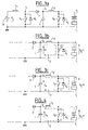
- FIG. 3a which is a diagram equivalent to the AC high voltage supply circuit of the piezoelectric injector P i , the computer sends a control signal to control the closing of the selection switch T i in order to that the piezoelectric actuator can be powered by this AC voltage.
- the control signal controls the closing of the switching switch S 2 so that the energy coming from the high Voltage V a accumulates in the inductance L 2 by circulation of a current i 2 in the loop consisting of the filtering capacitor C, the inductance L 2 and the switch S 2 .
- a second oscillation phase between the capacity of the injector and the inductance L 2 represented in FIG.
- the switch S 2 for switching is controlled at the opening, the current i 2 can not pass by the diode d 2 non-parallel anti-parallel is forced to flow in the actuator P i in one direction and then in the other because the inductance L 2 and the injector P i are in electrical resonance. Since the value of the inductance L 2 is a function of the acoustic excitation resonance of the piezoelectric actuator, it is determined so that the inductance L 2 has the time to charge sufficiently in the first phase so that the excitation voltage V pi at the terminals of the injector P i , close to 1200 volts, is reached. In addition, the filtering capacitor C is sized to have a very high reactivity to the voltage rise V a .
- FIG. 4 is a diagram equivalent to the discharge circuit of inductance L 2 .
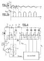
- FIGS. 5a and 5b which are the temporal representations of the current i 2 in the inductance L 2 and of the voltage V pi at the terminals of the injector P i , for a high supply voltage V a constant, the first phase of the supply sequence of the injector, corresponding to the accumulation of energy in the inductance L 2 , takes place between the times t0 and t1 when the current i 2 in the inductance L 2 increases by 0 to a maximum value i max .
- the second phase of the sequence takes place between t1 and t3: firstly between the instants t1 and t2 when the current i 2 i max decreases to 0 while the voltage V pi increases from 0 to a maximum value V pmax , close to 1200 Volts, which corresponds to the load of the injector, and then between the instants t2 and t3 from 0 to a minimum negative value i min while the voltage V pi decreases from the maximum value V pmax to 0 , and that corresponds to his discharge.
- the voltage V pi remains zero and the current i 2 increases again from the minimum value i min to 0.
- the piezoelectric actuator is in electrical resonance with the inductance L 2 .
- the period of electrical resonance between the piezoelectric actuator and the inductance L 2 corresponding to the second phase of the supply sequence of the actuator, between times t1 and t3, is shorter than the period of acoustic resonance corresponding to the three phases united between instants t1 to t4.
- This acoustic resonance depends on the characteristics of the piezoelectric injector.
- the actual phase of ac power supply of the injector P i between times t1 and t3 depends on the value of the inductance L 2 , the high voltage V has to be reached and the closing time of the switch I 2 to obtain the voltage V pi required.
- the control device comprises a fourth control stage of this excitation voltage V pi which will act as follows: the switch S 2 of the second stage is controlled so that at its closure, the inductance L 2 is charged for a certain time, and at its opening, the voltage across the selected injector describes a sinusoidal pulse.
- the peak value of this voltage V pi depends on the energy stored in the inductance L 2 and the high voltage V has generated.
- FIG. 6 is a complete electronic diagram of a device for controlling a plurality of piezoelectric actuators P i with control of their excitation voltage V pi .
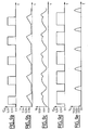
- the control method fixes on the one hand the duty cycle ⁇ S1 , or conduction angle, of the switching switch S 1 of the first stage to a constant value (FIG. 7a) so that the current i 1 flowing in the inductance L 1 (FIG. 7b) generates a high voltage V a at the output of the first stage which is relatively constant (FIG. 7c) and secondly the ratio cyclic ⁇ S2 , or conduction angle, of the switching switch S 2 for cutting the second stage (FIG. 7d), which makes it possible to obtain an excitation voltage V pi for the injectors whose waveform is represented on FIG. figure 7e.
- said control method varies, with respect to the previous fixed values, the cyclic ratio ⁇ S2 of the switching switch S 2 for cutting the second stage (FIG. 8d), while keeping the duty cycle ⁇ S1 of switch S 1 of the first stage ( Figure 8a), so as to vary the energy stored in the inductor L 2 , so the excitation voltage V pi of the injectors ( Figure 8e).
- ⁇ S2 of the switching switch S 2 for cutting the second stage FIG. 8d
- said duty cycle ⁇ S1 of switch S 1 of the first stage Figure 8a
- the electronic computer on the one hand sets the duty cycle, or conduction angle, of the switching switch of the second stage S 2 to a constant value and, on the other hand, varies the duty cycle, or angle of conduction, the switching switch of the first stage S 1 so that the high voltage V has the output of the first stage is adjustable and is the control parameter of the voltage V pi excitation of the injectors.
- the duty ratio ⁇ S 1 of the first switching switch S 1 which is equal to the conduction time t c divided by the period T of the signal, varies with respect to the first variant according to the control of the electronic computer (FIG. 9a), which causes a variation of the current i 1 in the inductance L 1 of the first stage of the control device ( FIG. 9b) and consequently a variation in the same direction of the high voltage V a across the capacitor C which is charged by virtue of the energy stored in said inductor L 1 (FIG. 9c).
- the duty ratio ⁇ S 2 of the second switching switch S 2 is constant with respect to the first variant (FIG. 9d) so that the excitation voltage V pi is a periodic signal of the same waveform and of which the peak value varies according to the value of the high voltage V a ( Figure 9e).
- the excitation voltage setpoint V pi determined by the desired injection performance by the injection system, can be translated into a high voltage setpoint V a to be followed by the output voltage of the second stage of the control device. For this, the output voltage of the second stage is measured and compared to the setpoint in a control loop intended to reduce the difference between these two values.
- the control means of this excitation voltage setpoint V pi comprise an electronic control computer 1, which may be that of the injection, which transforms this excitation voltage setpoint.
- V acons high voltage setpoint, to which will be compared the high voltage V a measured by a sensor 2, which is thus regulated by a regulator 3 Proportional Integral Derivative type for example.
- the difference ⁇ between the measured value and the setpoint value is transformed into an opening control signal ⁇ S 1 of the switching switch S 1 , by a variable width pulse generator (PWM) 4 which will enable to realize the high voltage V is necessary to obtain the excitation voltage.
- PWM variable width pulse generator
- This high voltage V a necessary for obtaining the excitation voltage V pi may also be obtained by calibration according to the used injectors.
- the control of the excitation voltage V pi of the injectors is simple to implement because only the high supply voltage V a is the parameter used to control it. Moreover, the regulation of the excitation voltage V pi by the control of the high voltage V a makes it possible to size the power electronics in a very reactive manner and therefore to size the filtering capacitor C as the power components, ie the S 1 and S 2 switches, at their minimum size.
- the control device of an ultrasonic piezoelectric injector comprises an additional step of controlling the closing of the switching switch S 2 of the second generation stage of a source supply current of the injectors, when the voltage at its terminals is zero, that is to say when the excitation voltage V pi of the piloted injector is zero. For that, one can measure the voltage U 2mes between its collector and its emitter and to authorize its closing only if its value is lower than a threshold close to zero.
- This closing control step can be performed entirely by logic control means, by state machine for example providing voltage control when the voltage across the switch S 2 is almost zero.
- analog control means such as a threshold transistor T, of PNP type if the switch S 2 is an NPN transistor, receiving a signal of command U com of the control computer 1 on its transmitter and whose base receives the voltage existing across the switch S 2 . If the difference between the control voltage and the measured voltage U com - U 2mes , is less than a threshold, determined according to the characteristics of the transistors, the threshold transistor T leads and lets the closing control signal through its collector. which is connected to the base of the switch S 2 , via a resistor R for example. A discharge stage E d of the transistor T threshold is provided between its collector and its ground in the case where the closing of the switch S 2 is not allowed.
- the advantage of controlling when closing the switch of the second stage of the device when the excitation voltage V pi of the injectors is close to zero is to limit the losses by switching in the switches, whatever the variations in the time of the period of the excitation signal of the injectors. It is thus possible to ensure the control at the closing whatever the variation of the parameters of the electronics - tolerance of the components, the input impedance of the injectors, variations of the supply voltages or intermediate commands as the duration charging of inductances, the accuracy of the control of the high voltage supply Va, ... - or drifts in time of these components or drifts related to the ambient temperature, which can vary from -40 ° C to + 150 ° C.
Applications Claiming Priority (2)
| Application Number | Priority Date | Filing Date | Title |
|---|---|---|---|
| FR0214665A FR2847743B1 (fr) | 2002-11-22 | 2002-11-22 | Dispositif de commande d'un actuateur piezo-electrique ultrasonore et procede de mise en oeuvre |
| FR0214665 | 2002-11-22 |
Publications (3)
| Publication Number | Publication Date |
|---|---|
| EP1422764A2 true EP1422764A2 (de) | 2004-05-26 |
| EP1422764A3 EP1422764A3 (de) | 2010-04-28 |
| EP1422764B1 EP1422764B1 (de) | 2011-04-06 |
Family
ID=32187800
Family Applications (1)
| Application Number | Title | Priority Date | Filing Date |
|---|---|---|---|
| EP03292785A Expired - Lifetime EP1422764B1 (de) | 2002-11-22 | 2003-11-06 | Steuervorrichtung für einen piezoelektrischen Ultraschallaktuator und Betriebsverfahren |
Country Status (4)
| Country | Link |
|---|---|
| EP (1) | EP1422764B1 (de) |
| AT (1) | ATE504729T1 (de) |
| DE (1) | DE60336620D1 (de) |
| FR (1) | FR2847743B1 (de) |
Cited By (5)
| Publication number | Priority date | Publication date | Assignee | Title |
|---|---|---|---|---|
| FR2879257A1 (fr) * | 2004-12-14 | 2006-06-16 | Renault Sas | Dispositif de commande electronique pour actionneurs piezo-electriques ultrasonores |
| FR2879255A1 (fr) * | 2004-12-14 | 2006-06-16 | Renault Sas | Procede de pilotage electronique d'un actionneur piezo-electrique ultrasonore |
| WO2007023159A1 (de) * | 2005-08-26 | 2007-03-01 | Vdo Automotive Ag | Stromquelle, steuervorrichtung und verfahren zum betreiben der steuervorrichtung |
| WO2007135339A1 (fr) * | 2006-05-24 | 2007-11-29 | Renault S.A.S | Dispositif de commande d'un injecteur piezo-electrique ultrasonore |
| WO2021035616A1 (zh) * | 2019-08-29 | 2021-03-04 | 深圳市大疆创新科技有限公司 | 驱动电路、驱动电路板与驱动器 |
Citations (3)
| Publication number | Priority date | Publication date | Assignee | Title |
|---|---|---|---|---|
| DE19709715A1 (de) * | 1997-03-10 | 1998-05-20 | Siemens Ag | Vorrichtung und Verfahren zum Ansteuern wenigstens eines kapazitiven Stellgliedes |
| DE19714610A1 (de) * | 1997-04-09 | 1998-10-15 | Bosch Gmbh Robert | Verfahren und Vorrichtung zum Laden und Entladen eines piezoelektrischen Elements |
| DE10151421A1 (de) * | 2000-10-19 | 2002-05-29 | Nippon Soken | Piezobetätigungsgliedantriebsschaltung und Kraftstoffeinspritzgerät |
-
2002
- 2002-11-22 FR FR0214665A patent/FR2847743B1/fr not_active Expired - Fee Related
-
2003
- 2003-11-06 EP EP03292785A patent/EP1422764B1/de not_active Expired - Lifetime
- 2003-11-06 DE DE60336620T patent/DE60336620D1/de not_active Expired - Lifetime
- 2003-11-06 AT AT03292785T patent/ATE504729T1/de not_active IP Right Cessation
Patent Citations (3)
| Publication number | Priority date | Publication date | Assignee | Title |
|---|---|---|---|---|
| DE19709715A1 (de) * | 1997-03-10 | 1998-05-20 | Siemens Ag | Vorrichtung und Verfahren zum Ansteuern wenigstens eines kapazitiven Stellgliedes |
| DE19714610A1 (de) * | 1997-04-09 | 1998-10-15 | Bosch Gmbh Robert | Verfahren und Vorrichtung zum Laden und Entladen eines piezoelektrischen Elements |
| DE10151421A1 (de) * | 2000-10-19 | 2002-05-29 | Nippon Soken | Piezobetätigungsgliedantriebsschaltung und Kraftstoffeinspritzgerät |
Cited By (9)
| Publication number | Priority date | Publication date | Assignee | Title |
|---|---|---|---|---|
| FR2879257A1 (fr) * | 2004-12-14 | 2006-06-16 | Renault Sas | Dispositif de commande electronique pour actionneurs piezo-electriques ultrasonores |
| FR2879255A1 (fr) * | 2004-12-14 | 2006-06-16 | Renault Sas | Procede de pilotage electronique d'un actionneur piezo-electrique ultrasonore |
| WO2006064147A1 (fr) * | 2004-12-14 | 2006-06-22 | Renault S.A.S | Dispositif de commande electronique pour actionneurs piezo-electriques ultrasonores |
| WO2006077295A1 (fr) * | 2004-12-14 | 2006-07-27 | Renault S.A.S | Procede de pilotage electronique d'un actionneur piezo-electrique ultrasonore |
| WO2007023159A1 (de) * | 2005-08-26 | 2007-03-01 | Vdo Automotive Ag | Stromquelle, steuervorrichtung und verfahren zum betreiben der steuervorrichtung |
| CN101310102B (zh) * | 2005-08-26 | 2011-04-13 | 欧陆汽车有限责任公司 | 电源、控制装置以及运行控制装置的方法 |
| KR101248987B1 (ko) * | 2005-08-26 | 2013-03-29 | 콘티넨탈 오토모티브 게엠베하 | 전류 소스, 제어 디바이스 그리고 상기 제어 디바이스를 작동시키기 위한 방법 |
| WO2007135339A1 (fr) * | 2006-05-24 | 2007-11-29 | Renault S.A.S | Dispositif de commande d'un injecteur piezo-electrique ultrasonore |
| WO2021035616A1 (zh) * | 2019-08-29 | 2021-03-04 | 深圳市大疆创新科技有限公司 | 驱动电路、驱动电路板与驱动器 |
Also Published As
| Publication number | Publication date |
|---|---|
| DE60336620D1 (de) | 2011-05-19 |
| ATE504729T1 (de) | 2011-04-15 |
| FR2847743A1 (fr) | 2004-05-28 |
| FR2847743B1 (fr) | 2005-02-11 |
| EP1422764B1 (de) | 2011-04-06 |
| EP1422764A3 (de) | 2010-04-28 |
Similar Documents
| Publication | Publication Date | Title |
|---|---|---|
| EP1537608B1 (de) | Verfahren zum elektronischen betrieb einer steuereinrichtung für ein piezobetätigungsglied | |
| EP2005491B1 (de) | Vorrichtung und verfahren zum antrieb von mehreren ultraschall-piezoaktoren | |
| US20080116855A1 (en) | Method and Device for Controlling a Capacitive Load | |
| EP1422764B1 (de) | Steuervorrichtung für einen piezoelektrischen Ultraschallaktuator und Betriebsverfahren | |
| EP1446843A2 (de) | Elektronische steuervorrichtung für einen piezoelektrischen ultraschallaktuator und deren betriebsverfahren | |
| EP2334922A1 (de) | Vorrichtung und verfahren zur steuerung eines piezoelektrischen resonanz-ultraschallinjektors | |
| EP1067608B1 (de) | Anordnung und Steuerschaltung eines piezoelektrisches Antriebs | |
| EP2218161B1 (de) | Vorrichtung zur steuerung eines piezoelektrischen ultraschallinjektors | |
| WO2003038918A2 (fr) | Dispositif de commande d'un actuateur piezo-electrique | |
| EP1469183B1 (de) | Steuervorrichtung für einen piezoelektrischen Ultraschallaktuator sowie Betriebsverfahren | |
| EP1528605B1 (de) | Steuervorrichtung für piezoelektrische Ultraschallaktoren | |
| WO2006077295A1 (fr) | Procede de pilotage electronique d'un actionneur piezo-electrique ultrasonore | |
| EP1828584B1 (de) | Vorrichtung zur elektronischen steuerung von piezoelektrischen ultraschallaktuatoren | |
| EP1471239A1 (de) | Steuervorrichtung für einen piezoelektrischen Ultraschallaktuator und Betriebsverfahren | |
| WO2006042997A1 (fr) | Procede et dispositif de pilotage d'injecteurs piezo-electriques ultrasonores pour moteur thermique | |
| FR2813455A1 (fr) | Dispositif de commande d'une ceramique piezo-electrique, notamment pour un actionneur d'injecteur de moteur a combustion interne | |
| WO2007135339A1 (fr) | Dispositif de commande d'un injecteur piezo-electrique ultrasonore | |
| FR2861919A1 (fr) | Dispositif de commande de plusieurs actionneurs piezo-electriques ultrasonores | |
| FR2879256A1 (fr) | Dispositif de commande electronique d'actionneurs piezo-electriques | |
| EP1211792A1 (de) | Gleichstrom-Spannungswandler | |
| EP0323318A1 (de) | Gerät zur Steuerung und Prüfung von Kraftstoffeinspritzventilen eines Mehrzylinder-Verbrennungsmotors, insbesondere eines Zweitaktmotors | |
| FR2922694A1 (fr) | Procede de commande d'une alimentation de decoupage et alimentation correspondante |
Legal Events
| Date | Code | Title | Description |
|---|---|---|---|
| PUAI | Public reference made under article 153(3) epc to a published international application that has entered the european phase |
Free format text: ORIGINAL CODE: 0009012 |
|
| AK | Designated contracting states |
Kind code of ref document: A2 Designated state(s): AT BE BG CH CY CZ DE DK EE ES FI FR GB GR HU IE IT LI LU MC NL PT RO SE SI SK TR |
|
| AX | Request for extension of the european patent |
Extension state: AL LT LV MK |
|
| PUAL | Search report despatched |
Free format text: ORIGINAL CODE: 0009013 |
|
| AK | Designated contracting states |
Kind code of ref document: A3 Designated state(s): AT BE BG CH CY CZ DE DK EE ES FI FR GB GR HU IE IT LI LU MC NL PT RO SE SI SK TR |
|
| AX | Request for extension of the european patent |
Extension state: AL LT LV MK |
|
| RIC1 | Information provided on ipc code assigned before grant |
Ipc: F02D 41/20 20060101AFI20100325BHEP Ipc: H01L 41/04 20060101ALI20100325BHEP |
|
| 17P | Request for examination filed |
Effective date: 20100527 |
|
| GRAP | Despatch of communication of intention to grant a patent |
Free format text: ORIGINAL CODE: EPIDOSNIGR1 |
|
| RIC1 | Information provided on ipc code assigned before grant |
Ipc: H01L 41/04 20060101ALI20100914BHEP Ipc: F02D 41/20 20060101AFI20100914BHEP |
|
| AKX | Designation fees paid |
Designated state(s): AT BE BG CH CY CZ DE DK EE ES FI FR GB GR HU IE IT LI LU MC NL PT RO SE SI SK TR |
|
| GRAS | Grant fee paid |
Free format text: ORIGINAL CODE: EPIDOSNIGR3 |
|
| GRAA | (expected) grant |
Free format text: ORIGINAL CODE: 0009210 |
|
| AK | Designated contracting states |
Kind code of ref document: B1 Designated state(s): AT BE BG CH CY CZ DE DK EE ES FI FR GB GR HU IE IT LI LU MC NL PT RO SE SI SK TR |
|
| REG | Reference to a national code |
Ref country code: GB Ref legal event code: FG4D Free format text: NOT ENGLISH |
|
| REG | Reference to a national code |
Ref country code: CH Ref legal event code: EP |
|
| REG | Reference to a national code |
Ref country code: IE Ref legal event code: FG4D |
|
| REF | Corresponds to: |
Ref document number: 60336620 Country of ref document: DE Date of ref document: 20110519 Kind code of ref document: P |
|
| REG | Reference to a national code |
Ref country code: DE Ref legal event code: R096 Ref document number: 60336620 Country of ref document: DE Effective date: 20110519 |
|
| REG | Reference to a national code |
Ref country code: NL Ref legal event code: VDEP Effective date: 20110406 |
|
| PG25 | Lapsed in a contracting state [announced via postgrant information from national office to epo] |
Ref country code: SI Free format text: LAPSE BECAUSE OF FAILURE TO SUBMIT A TRANSLATION OF THE DESCRIPTION OR TO PAY THE FEE WITHIN THE PRESCRIBED TIME-LIMIT Effective date: 20110406 |
|
| REG | Reference to a national code |
Ref country code: IE Ref legal event code: FD4D |
|
| PG25 | Lapsed in a contracting state [announced via postgrant information from national office to epo] |
Ref country code: SE Free format text: LAPSE BECAUSE OF FAILURE TO SUBMIT A TRANSLATION OF THE DESCRIPTION OR TO PAY THE FEE WITHIN THE PRESCRIBED TIME-LIMIT Effective date: 20110406 Ref country code: PT Free format text: LAPSE BECAUSE OF FAILURE TO SUBMIT A TRANSLATION OF THE DESCRIPTION OR TO PAY THE FEE WITHIN THE PRESCRIBED TIME-LIMIT Effective date: 20110808 |
|
| PG25 | Lapsed in a contracting state [announced via postgrant information from national office to epo] |
Ref country code: CY Free format text: LAPSE BECAUSE OF FAILURE TO SUBMIT A TRANSLATION OF THE DESCRIPTION OR TO PAY THE FEE WITHIN THE PRESCRIBED TIME-LIMIT Effective date: 20110406 Ref country code: GR Free format text: LAPSE BECAUSE OF FAILURE TO SUBMIT A TRANSLATION OF THE DESCRIPTION OR TO PAY THE FEE WITHIN THE PRESCRIBED TIME-LIMIT Effective date: 20110707 Ref country code: ES Free format text: LAPSE BECAUSE OF FAILURE TO SUBMIT A TRANSLATION OF THE DESCRIPTION OR TO PAY THE FEE WITHIN THE PRESCRIBED TIME-LIMIT Effective date: 20110717 Ref country code: AT Free format text: LAPSE BECAUSE OF FAILURE TO SUBMIT A TRANSLATION OF THE DESCRIPTION OR TO PAY THE FEE WITHIN THE PRESCRIBED TIME-LIMIT Effective date: 20110406 Ref country code: FI Free format text: LAPSE BECAUSE OF FAILURE TO SUBMIT A TRANSLATION OF THE DESCRIPTION OR TO PAY THE FEE WITHIN THE PRESCRIBED TIME-LIMIT Effective date: 20110406 |
|
| PG25 | Lapsed in a contracting state [announced via postgrant information from national office to epo] |
Ref country code: NL Free format text: LAPSE BECAUSE OF FAILURE TO SUBMIT A TRANSLATION OF THE DESCRIPTION OR TO PAY THE FEE WITHIN THE PRESCRIBED TIME-LIMIT Effective date: 20110406 |
|
| PG25 | Lapsed in a contracting state [announced via postgrant information from national office to epo] |
Ref country code: CZ Free format text: LAPSE BECAUSE OF FAILURE TO SUBMIT A TRANSLATION OF THE DESCRIPTION OR TO PAY THE FEE WITHIN THE PRESCRIBED TIME-LIMIT Effective date: 20110406 Ref country code: IE Free format text: LAPSE BECAUSE OF FAILURE TO SUBMIT A TRANSLATION OF THE DESCRIPTION OR TO PAY THE FEE WITHIN THE PRESCRIBED TIME-LIMIT Effective date: 20110406 Ref country code: EE Free format text: LAPSE BECAUSE OF FAILURE TO SUBMIT A TRANSLATION OF THE DESCRIPTION OR TO PAY THE FEE WITHIN THE PRESCRIBED TIME-LIMIT Effective date: 20110406 |
|
| PLBE | No opposition filed within time limit |
Free format text: ORIGINAL CODE: 0009261 |
|
| STAA | Information on the status of an ep patent application or granted ep patent |
Free format text: STATUS: NO OPPOSITION FILED WITHIN TIME LIMIT |
|
| PG25 | Lapsed in a contracting state [announced via postgrant information from national office to epo] |
Ref country code: SK Free format text: LAPSE BECAUSE OF FAILURE TO SUBMIT A TRANSLATION OF THE DESCRIPTION OR TO PAY THE FEE WITHIN THE PRESCRIBED TIME-LIMIT Effective date: 20110406 Ref country code: DK Free format text: LAPSE BECAUSE OF FAILURE TO SUBMIT A TRANSLATION OF THE DESCRIPTION OR TO PAY THE FEE WITHIN THE PRESCRIBED TIME-LIMIT Effective date: 20110406 Ref country code: RO Free format text: LAPSE BECAUSE OF FAILURE TO SUBMIT A TRANSLATION OF THE DESCRIPTION OR TO PAY THE FEE WITHIN THE PRESCRIBED TIME-LIMIT Effective date: 20110406 |
|
| 26N | No opposition filed |
Effective date: 20120110 |
|
| REG | Reference to a national code |
Ref country code: DE Ref legal event code: R097 Ref document number: 60336620 Country of ref document: DE Effective date: 20120110 |
|
| BERE | Be: lapsed |
Owner name: RENAULT S.A.S. Effective date: 20111130 |
|
| PG25 | Lapsed in a contracting state [announced via postgrant information from national office to epo] |
Ref country code: MC Free format text: LAPSE BECAUSE OF NON-PAYMENT OF DUE FEES Effective date: 20111130 |
|
| REG | Reference to a national code |
Ref country code: CH Ref legal event code: PL |
|
| PG25 | Lapsed in a contracting state [announced via postgrant information from national office to epo] |
Ref country code: LI Free format text: LAPSE BECAUSE OF NON-PAYMENT OF DUE FEES Effective date: 20111130 Ref country code: CH Free format text: LAPSE BECAUSE OF NON-PAYMENT OF DUE FEES Effective date: 20111130 |
|
| PG25 | Lapsed in a contracting state [announced via postgrant information from national office to epo] |
Ref country code: BE Free format text: LAPSE BECAUSE OF NON-PAYMENT OF DUE FEES Effective date: 20111130 |
|
| PG25 | Lapsed in a contracting state [announced via postgrant information from national office to epo] |
Ref country code: LU Free format text: LAPSE BECAUSE OF NON-PAYMENT OF DUE FEES Effective date: 20111106 |
|
| PG25 | Lapsed in a contracting state [announced via postgrant information from national office to epo] |
Ref country code: BG Free format text: LAPSE BECAUSE OF FAILURE TO SUBMIT A TRANSLATION OF THE DESCRIPTION OR TO PAY THE FEE WITHIN THE PRESCRIBED TIME-LIMIT Effective date: 20110706 |
|
| PG25 | Lapsed in a contracting state [announced via postgrant information from national office to epo] |
Ref country code: TR Free format text: LAPSE BECAUSE OF FAILURE TO SUBMIT A TRANSLATION OF THE DESCRIPTION OR TO PAY THE FEE WITHIN THE PRESCRIBED TIME-LIMIT Effective date: 20110406 |
|
| PG25 | Lapsed in a contracting state [announced via postgrant information from national office to epo] |
Ref country code: HU Free format text: LAPSE BECAUSE OF FAILURE TO SUBMIT A TRANSLATION OF THE DESCRIPTION OR TO PAY THE FEE WITHIN THE PRESCRIBED TIME-LIMIT Effective date: 20110406 |
|
| PG25 | Lapsed in a contracting state [announced via postgrant information from national office to epo] |
Ref country code: IT Free format text: LAPSE BECAUSE OF FAILURE TO SUBMIT A TRANSLATION OF THE DESCRIPTION OR TO PAY THE FEE WITHIN THE PRESCRIBED TIME-LIMIT Effective date: 20110406 |
|
| REG | Reference to a national code |
Ref country code: FR Ref legal event code: PLFP Year of fee payment: 13 |
|
| REG | Reference to a national code |
Ref country code: FR Ref legal event code: PLFP Year of fee payment: 14 |
|
| REG | Reference to a national code |
Ref country code: FR Ref legal event code: PLFP Year of fee payment: 15 |
|
| PGFP | Annual fee paid to national office [announced via postgrant information from national office to epo] |
Ref country code: DE Payment date: 20171121 Year of fee payment: 15 Ref country code: FR Payment date: 20171121 Year of fee payment: 15 |
|
| PGFP | Annual fee paid to national office [announced via postgrant information from national office to epo] |
Ref country code: GB Payment date: 20171123 Year of fee payment: 15 |
|
| REG | Reference to a national code |
Ref country code: DE Ref legal event code: R119 Ref document number: 60336620 Country of ref document: DE |
|
| GBPC | Gb: european patent ceased through non-payment of renewal fee |
Effective date: 20181106 |
|
| PG25 | Lapsed in a contracting state [announced via postgrant information from national office to epo] |
Ref country code: FR Free format text: LAPSE BECAUSE OF NON-PAYMENT OF DUE FEES Effective date: 20181130 Ref country code: DE Free format text: LAPSE BECAUSE OF NON-PAYMENT OF DUE FEES Effective date: 20190601 |
|
| PG25 | Lapsed in a contracting state [announced via postgrant information from national office to epo] |
Ref country code: GB Free format text: LAPSE BECAUSE OF NON-PAYMENT OF DUE FEES Effective date: 20181106 |