EP1422475A1 - Dispositif de chauffage à brûleurs à gaz - Google Patents
Dispositif de chauffage à brûleurs à gaz Download PDFInfo
- Publication number
- EP1422475A1 EP1422475A1 EP03292863A EP03292863A EP1422475A1 EP 1422475 A1 EP1422475 A1 EP 1422475A1 EP 03292863 A EP03292863 A EP 03292863A EP 03292863 A EP03292863 A EP 03292863A EP 1422475 A1 EP1422475 A1 EP 1422475A1
- Authority
- EP
- European Patent Office
- Prior art keywords
- burner
- burners
- flame
- power
- power stage
- Prior art date
- Legal status (The legal status is an assumption and is not a legal conclusion. Google has not performed a legal analysis and makes no representation as to the accuracy of the status listed.)
- Granted
Links
- 238000010438 heat treatment Methods 0.000 title claims abstract description 40
- 239000000203 mixture Substances 0.000 claims description 18
- 238000002485 combustion reaction Methods 0.000 claims description 10
- 230000004913 activation Effects 0.000 claims description 3
- 230000003287 optical effect Effects 0.000 claims description 2
- 239000007789 gas Substances 0.000 description 39
- 230000007704 transition Effects 0.000 description 6
- 238000009434 installation Methods 0.000 description 3
- 239000003517 fume Substances 0.000 description 2
- 230000000717 retained effect Effects 0.000 description 2
- 239000000523 sample Substances 0.000 description 2
- 230000000694 effects Effects 0.000 description 1
- 244000144972 livestock Species 0.000 description 1
- 239000002184 metal Substances 0.000 description 1
- 238000010792 warming Methods 0.000 description 1
Images
Classifications
-
- F—MECHANICAL ENGINEERING; LIGHTING; HEATING; WEAPONS; BLASTING
- F23—COMBUSTION APPARATUS; COMBUSTION PROCESSES
- F23D—BURNERS
- F23D23/00—Assemblies of two or more burners
-
- F—MECHANICAL ENGINEERING; LIGHTING; HEATING; WEAPONS; BLASTING
- F23—COMBUSTION APPARATUS; COMBUSTION PROCESSES
- F23D—BURNERS
- F23D14/00—Burners for combustion of a gas, e.g. of a gas stored under pressure as a liquid
- F23D14/02—Premix gas burners, i.e. in which gaseous fuel is mixed with combustion air upstream of the combustion zone
- F23D14/04—Premix gas burners, i.e. in which gaseous fuel is mixed with combustion air upstream of the combustion zone induction type, e.g. Bunsen burner
- F23D14/045—Premix gas burners, i.e. in which gaseous fuel is mixed with combustion air upstream of the combustion zone induction type, e.g. Bunsen burner with a plurality of burner bars assembled together, e.g. in a grid-like arrangement
-
- F—MECHANICAL ENGINEERING; LIGHTING; HEATING; WEAPONS; BLASTING
- F23—COMBUSTION APPARATUS; COMBUSTION PROCESSES
- F23D—BURNERS
- F23D2207/00—Ignition devices associated with burner
-
- F—MECHANICAL ENGINEERING; LIGHTING; HEATING; WEAPONS; BLASTING
- F23—COMBUSTION APPARATUS; COMBUSTION PROCESSES
- F23N—REGULATING OR CONTROLLING COMBUSTION
- F23N2227/00—Ignition or checking
- F23N2227/10—Sequential burner running
-
- F—MECHANICAL ENGINEERING; LIGHTING; HEATING; WEAPONS; BLASTING
- F23—COMBUSTION APPARATUS; COMBUSTION PROCESSES
- F23N—REGULATING OR CONTROLLING COMBUSTION
- F23N2237/00—Controlling
- F23N2237/02—Controlling two or more burners
-
- F—MECHANICAL ENGINEERING; LIGHTING; HEATING; WEAPONS; BLASTING
- F23—COMBUSTION APPARATUS; COMBUSTION PROCESSES
- F23N—REGULATING OR CONTROLLING COMBUSTION
- F23N2237/00—Controlling
- F23N2237/10—High or low fire
Definitions
- the present invention relates to a heating device with gas burners.
- Gas burners are widely used today, especially for air heating, especially in livestock buildings. Disadvantage major of these burners lies in their reduced power range. Indeed, their operation, based on the ignition of an air / gas mixture, requires a compliance with the proportions of the components in the mixture. It is therefore impossible to vary significantly the amount of gas in the mixing without risking extinguishing the flame. Therefore, the trend today is to use powerful burners which are frequently switched between on and off positions for temperature regulation. It results from user comfort problems due to the inertia of its burners.
- a heating device To be able to cover a large power range without having to have powerful burners, a heating device has been devised several gas burners of the same power.
- the burners are divided into a burner, called a master, equipped with a device of ignition of air / gas mixture and in burners, called slaves, free of such device.
- the transition from one power stage to another is carried out by ignition of the burner immediately adjacent to the burner previously lit. This results in the obligation to carry out the lighting of said burners in an order predetermined according to the relative positioning of the burners on the pipe common gas supply.
- this solution may cover a large power range, the number of power stages is reduced and the stages between power stages are of constant value. This is due to fact that the gas burners used are all of the same power and that only ignition of a burner, immediately adjacent to a previously burner on, can be considered. Burner combinations are therefore limited.
- An object of the present invention is to overcome the aforementioned drawbacks by offering a heating device whose design allows variation power over a wide range, the value of the steps between stages of power can be freely chosen by the user so as to offer a great number of possibilities to the latter.
- Another object of the present invention is to provide a heating device whose number of burners, although reduced, allows a variation of power within a wide range while ensuring operation optimal and perfectly safe flame control device.
- Another object of the present invention is to provide a heating device simple in design and the number of parts can be reduced without affecting the safety of the whole.
- Another object of the present invention is to provide a heating device having a large number of power stages for a given number of burners, each power stage corresponding to a combination predetermined burners arranged in any manner in the device.
- the invention relates to a heating device of the type constituted at least three burners, respectively connected to a common line gas supply, itself connected to a gas supply source, each burner can be independently supplied with gas by via a lockable link with controlled opening / closing between the gas supply source and the burner, the burners being at least two types differing in their heating power, these burners being associated according to different selectable combinations corresponding each with a power stage, the control means opening / closing of the link of each controlling burner, when transition from a power stage N to a selected power stage P, the opening of the link of the burner (s) to light on the power stage P selected and at least the opening of the connections of all the burners separating a burner lit on the power stage N from a burner to be lit at the power stage P to allow automatic ignition of the flame of each burner by contact with the air / gas mixture expelled from said burner with the flame of an adjacent burner until the burner ignites at stage P selected then selective closing of burner connections not included in the combination corresponding to the power stage P selected,
- the device flame control can be common to all burners and activated by any of the burners due to the fact that when passing through a stage of power to another, all burners work.
- a release of sufficient heat to guarantee continued operation of the flame control in the case of a device operating by infrared either the temperature rise of the probe in the case of a control device of the flame operating by ionization.
- This ignition of all burners during the transitional period thus makes it possible to pass from a stage of power to another without having any common burner lit between the two stages thus increasing the number of combinations and as a result of power possible.
- the heating device is consisting of burners 1 connected to a rigid gas supply pipe 2, generally metallic, itself connected to a power source 3 gas which can be any.
- the whole forms what one could call a gas burner burner 1.
- the burners 1 act conventionally by combustion of an air / gas mixture.
- These burners 1 can be of the type atmospheric or dynamic. In such a device, these burners 1 will be at fewer than three.
- Each burner 1 comprises, per se known, a duct comprising at least one combustion air inlet primary and containing at least the gas injector and a mixing chamber air / gas, this conduit opening into a combustion chamber of the mixture air / gas.
- the duct contains, between the injector and the air / gas mixing chamber, a venturi element. The detail of such burners will not be provided because many examples of embodiment of burners can be found in the literature.
- the heating device object of the invention, there is preferably a distinction two types of burners, namely a so-called master burner, fitted with a device 4 of the air / gas mixture ignition and of the burners 1, called slaves, which differentiate from the master burner by the fact that they are device-free ignition of the air / gas mixture.
- the device 4 for igniting the mixture air / gas will not be described in detail since it can be constituted in itself known from an electrical device of resistance, sparks or other type, from a night light or the like.
- Each burner comprises at least one device 11 for flame control. This flame control device 11 is thus common to all burners.
- This flame control device 11 can be consisting of an optical device, an ionization device, a infrared or any other means which ensures, when the flame, closing the supply to the common supply line gas from the gas supply source by means of a valve appropriate closure.
- this device 11 is a device to ionization consisting of a probe and a metal rod coming to cap the middle burner and extending along each of the burners adjoining this median burner. The cooperation of this flame control device 11 with the burner control means will be described below.
- Each burner 1, master or slave, is connected to the power source 3 in gas via the common gas supply line 2 and a tap on said pipe 2.
- Each connecting portion 5, produced between the source 3 of gas supply and a burner 1 is provided with a member 6 such that a solenoid valve ensuring the opening or closing of the link 5 between the burner 1 and source 3 of gas supply.
- This opening / closing of the link 5 is controlled by means of a suitable control device in depending on the power stage selected.
- the heater comprises a plurality of burners 1. Among these burners, there are at least two types of burners 1 differentiated by their heating power. Of preferably, the lower power burner 1 is placed between two other burners 1.
- burners are associated in operation according to combinations any predetermined randomly selectable for example by means of a programmer, each combination corresponding to a power stage. So it can be imagined a device heater with four burners with heating output differentiated.
- the first stage corresponds to the operation of the master burner of lower power
- the second power stage to the combination of lower power burner with power burner immediately above ...
- the top floor corresponding to a combination where the whole burners are working, i.e. are lit.
- the heating device therefore further comprises means for selecting a power stage corresponding to a predetermined combination of burner (s) in operation from a plurality of stages.
- selection means can be constituted by a programmer.
- it can be chosen, for a heating device comprising four burners, respectively called B1, B2, B3, B4, to define a first power stage corresponding to a supply of air / gas mixture of B1, the connections of the other burners remaining closed.
- a second power stage can be defined in which only the burner B3 of a power different from the burner B1 is lit.
- Other combinations can thus be defined, the total number of combinations being at most equal to 2 x , x corresponding to the number of burners in the installation.
- the means 7 for controlling the opening / closing of the connection of each burner control when passing from a power stage N to any new power stage P selected at any point, the opening of all the connections 5 of the burners 1 to allow, by automatic ignition of the flame of a burner by contact of the air / gas mixture expelled from the burner with the flame of an adjacent burner, the ignition of all the burners then the selective closing of the burner links 5 not included in the combination corresponding to the new selected power stage.
- This solution makes it possible to dispense with means of memorizing the combinations of burners coupled to means 7 for controlling opening / closing links. Thus, between each passage of a stage of power to another, all the burners are put into operation by automatic opening of links 5. On the other hand, this solution allows guarantee activation of the flame control device 11 by one any of the burners, regardless of the power level selected.
- the controlled opening / closing shutter member 6 of the link 5 between a burner 1 and the gas supply source 3 is a solenoid valve.
- the opening / closing of the solenoid valves can be controlled by means of electrical signals emitted from information emanating from a central control, such as a microprocessor. This central manages information relating to the power stage selected to determine the connections in front be open or closed respectively.
- the interval between two adjacent burner heads is chosen so as to allow self-ignition two adjacent burners in less than a tenth of a second.
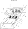
- the burners 1 are arranged at at least partially inside a combustion chamber 8, itself housed inside a box 9 of a temperature-controlled air generator, this box 9 also containing at least one fan 10 for propelling in a room, at the desired temperature, the air circulating in the box 9.
- This air can thus be brought to temperature by conduction in contact with the walls of the combustion chamber 8.
- the exhaust air can consist exclusively of this air heated in contact with the walls of the combustion chamber 8 or also consist of the fumes from the combustion chamber 8.
Landscapes
- Engineering & Computer Science (AREA)
- Chemical & Material Sciences (AREA)
- Combustion & Propulsion (AREA)
- Mechanical Engineering (AREA)
- General Engineering & Computer Science (AREA)
- Regulation And Control Of Combustion (AREA)
- Control Of Combustion (AREA)
- Incineration Of Waste (AREA)
- Feeding And Controlling Fuel (AREA)
- Gas Burners (AREA)
Abstract
Description
| Etage de puissance | B1 | B2 | B3 | B4 |
| N | 0 | F | F | F |
| Etape de transition | B1 | B2 | B3 | B4 |
| 0 | 0 | 0 | 0 | |
| Etage de puissance | B1 | B2 | B3 | B4 |
| P | F | F | 0 | F |
Claims (9)
- Dispositif de chauffage du type constitué d'au moins trois brûleurs (1), respectivement raccordés à une conduite (2) commune d'alimentation en gaz, elle-même reliée à une source (3) d'alimentation en gaz, chaque brûleur (1) pouvant être indépendamment alimenté en gaz par l'intermédiaire d'une liaison (5) obturable à ouverture/fermeture commandée entre la source (3) d'alimentation en gaz et le brûleur (1), les brûleurs étant d'au moins deux types se différenciant par leur puissance de chauffe, ces brûleurs (1) étant associés suivant différentes combinaisons sélectionnables correspondant chacune à un étage de puissance, les moyens (7) de commande d'ouverture/fermeture de la liaison (5) de chaque brûleur (1) commandant, lors du passage d'un étage de puissance N à un étage de puissance P sélectionné, l'ouverture de la liaison (5) du ou des brûleur(s) (1) à allumer à l'étage de puissance P sélectionné et au moins l'ouverture des liaisons (5) de l'ensemble des brûleurs (1) séparant un brûleur (1) allumé à l'étage de puissance N d'un brûleur à allumer à l'étage de puissance P pour permettre une inflammation automatique de la flamme de chaque brûleur (1) par contact du mélange air/gaz expulsé dudit brûleur (1) avec la flamme d'un brûleur (1) adjacent jusqu'à allumage du brûleur (1) à allumer à l'étage P sélectionné puis la fermeture sélective des liaisons (5) des brûleurs (1) non inclus dans la combinaison correspondant à l'étage de puissance P sélectionné,
caractérisé en ce que le dispositif comporte au moins un dispositif (11) de contrôle de la flamme commun à tous les brûleurs et en ce que les moyens (7) de commande d'ouverture/fermeture de la liaison (5) de chaque brûleur (1) commandent, lors du passage d'un étage de puissance à un nouvel étage de puissance sélectionné, l'ouverture des liaisons (5) de tous les brûleurs (1) du dispositif pour permettre, par inflammation automatique de la flamme d'un brûleur (1) par contact du mélange air/gaz expulsé du brûleur avec la flamme d'un brûleur adjacent, l'allumage de tous les brûleurs puis la fermeture sélective des liaisons des brûleurs (1) non inclus dans la combinaison correspondant au nouvel étage de puissance sélectionné, cette commande permettant l'activation du dispositif (11 ) de contrôle de la flamme par l'un quelconque des brûleurs (1). - Dispositif de chauffage selon la revendication 1,
caractérisé en ce que l'organe (6) d'obturation à ouverture/fermeture commandée de la liaison (5) entre un brûleur (1) et la source (3) d'alimentation en gaz est une électrovanne. - Dispositif de chauffage selon l'une des revendications 1 et 2,
caractérisé en ce que les brûleurs (1) agissent par combustion d'un mélange air/gaz et sont du type atmosphérique ou dynamique. - Dispositif de chauffage selon l'une des revendications 1 à 3,
caractérisé en ce que l'intervalle entre deux têtes de brûleurs (1) adjacents est choisi de manière à permettre l'auto-inflammation des deux brûleurs adjacents en moins de un dixième de seconde. - Dispositif de chauffage selon l'une des revendications 1 à 4,
caractérisé en ce que les brûleurs (1) sont disposés au moins partiellement à l'intérieur d'une chambre (8) de combustion elle-même logée à l'intérieur d'un caisson (9) d'un générateur d'air à température contrôlée, ce caisson (9) renfermant en outre au moins un ventilateur (10) pour propulser dans un local, à température voulue, l'air circulant dans le caisson (9). - Dispositif de chauffage selon l'une des revendications 1 à 5,
caractérisé en ce que le dispositif (11) de contrôle de la flamme est un dispositif à ionisation provoquant, lors d'une extinction de la flamme, la fermeture de l'alimentation en gaz à partir de la source d'alimentation en gaz. - Dispositif de chauffage selon l'une des revendications 1 à 5,
caractérisé en ce que le dispositif (11 ) de contrôle de la flamme est un dispositif optique, de préférence à infrarouges provoquant, lors d'une extinction de la flamme, la fermeture de l'alimentation en gaz à partir de la source d'alimentation en gaz. - Dispositif de chauffage selon l'une des revendications 1 à 7,
caractérisé en ce que le brûleur (1) de plus faible puissance est disposé entre deux autres brûleurs (1). - Dispositif de chauffage selon l'une des revendications 1 à 8,
caractérisé en ce que les brûleurs (1) comprennent un brûleur (1) dit maítre équipé d'un dispositif (4) d'inflammation de mélange air/gaz et des brûleurs (1) esclaves exempts d'un tel dispositif d'inflammation.
Applications Claiming Priority (2)
| Application Number | Priority Date | Filing Date | Title |
|---|---|---|---|
| FR0214596A FR2847660B1 (fr) | 2002-11-21 | 2002-11-21 | Dispositif de chauffage a bruleurs a gaz |
| FR0214596 | 2002-11-21 |
Publications (2)
| Publication Number | Publication Date |
|---|---|
| EP1422475A1 true EP1422475A1 (fr) | 2004-05-26 |
| EP1422475B1 EP1422475B1 (fr) | 2006-11-29 |
Family
ID=32187788
Family Applications (1)
| Application Number | Title | Priority Date | Filing Date |
|---|---|---|---|
| EP03292863A Expired - Lifetime EP1422475B1 (fr) | 2002-11-21 | 2003-11-19 | Dispositif de chauffage à brûleurs à gaz |
Country Status (5)
| Country | Link |
|---|---|
| EP (1) | EP1422475B1 (fr) |
| AT (1) | ATE347072T1 (fr) |
| DE (1) | DE60310016T2 (fr) |
| ES (1) | ES2278129T3 (fr) |
| FR (1) | FR2847660B1 (fr) |
Cited By (4)
| Publication number | Priority date | Publication date | Assignee | Title |
|---|---|---|---|---|
| ITNA20090032A1 (it) * | 2009-05-27 | 2010-11-28 | Mario Provenza | Bruciatore atmosferico multigas specifico per l'alimentazione dei forni tradizionali e meccanici. |
| WO2011106824A1 (fr) * | 2010-03-03 | 2011-09-09 | Bromic Pty Limited | Appareil de chauffage résistant au vent |
| CN103277898A (zh) * | 2013-06-04 | 2013-09-04 | 樱花卫厨(中国)股份有限公司 | 热水器用燃烧器火力转换控制方式 |
| CN115560320A (zh) * | 2021-06-30 | 2023-01-03 | 芜湖美的厨卫电器制造有限公司 | 燃烧器及燃气热水器 |
Citations (10)
| Publication number | Priority date | Publication date | Assignee | Title |
|---|---|---|---|---|
| US4059385A (en) * | 1976-07-26 | 1977-11-22 | International Business Machines Corporation | Combustion monitoring and control system |
| US4163441A (en) * | 1978-04-05 | 1979-08-07 | Chen Tung C | System for reclaiming heat in a furnace arrangement |
| DE3927416A1 (de) * | 1989-08-19 | 1991-05-02 | Rolf Kresel | Variationsbrenner fuer gasfeuerungen in zentralheizungskesseln |
| WO1991016576A1 (fr) * | 1990-04-23 | 1991-10-31 | Italian Appliances Sas Di Enrico Sebastiani E C. | Procede de regulation d'un equipement a gaz generateur de chaleur et equipement correspondant |
| DE29518366U1 (de) * | 1995-11-18 | 1996-01-11 | Stiebel Eltron Gmbh & Co Kg, 37603 Holzminden | Zündvorrichtung für einen Gasbrenner |
| DE19832396A1 (de) * | 1998-06-19 | 1999-12-23 | Viessman Werke Gmbh & Co | Mehrstufiger, atmosphärischer Gasbrenner |
| FR2800848A1 (fr) * | 1999-11-05 | 2001-05-11 | Vergne Innovation | Procede pour regler un bruleur a gaz a becs multiples, ainsi que bruleur et chaudiere s'y rapportant |
| FR2800847A1 (fr) | 1999-11-05 | 2001-05-11 | Vergne Innovation | Procede pour regler un bruleur a gaz a becs multiples, ainsi que bruleur et chaudiere s'y rapportant |
| DE19958340A1 (de) * | 1999-12-03 | 2001-06-07 | Stiebel Eltron Gmbh & Co Kg | Gasbrenner mit Brennerlanzengruppen |
| DE10029234A1 (de) * | 2000-06-14 | 2001-10-25 | Rolf Kresel | Mehrstufige Gasarmatur |
-
2002
- 2002-11-21 FR FR0214596A patent/FR2847660B1/fr not_active Expired - Fee Related
-
2003
- 2003-11-19 EP EP03292863A patent/EP1422475B1/fr not_active Expired - Lifetime
- 2003-11-19 DE DE60310016T patent/DE60310016T2/de not_active Expired - Lifetime
- 2003-11-19 AT AT03292863T patent/ATE347072T1/de not_active IP Right Cessation
- 2003-11-19 ES ES03292863T patent/ES2278129T3/es not_active Expired - Lifetime
Patent Citations (10)
| Publication number | Priority date | Publication date | Assignee | Title |
|---|---|---|---|---|
| US4059385A (en) * | 1976-07-26 | 1977-11-22 | International Business Machines Corporation | Combustion monitoring and control system |
| US4163441A (en) * | 1978-04-05 | 1979-08-07 | Chen Tung C | System for reclaiming heat in a furnace arrangement |
| DE3927416A1 (de) * | 1989-08-19 | 1991-05-02 | Rolf Kresel | Variationsbrenner fuer gasfeuerungen in zentralheizungskesseln |
| WO1991016576A1 (fr) * | 1990-04-23 | 1991-10-31 | Italian Appliances Sas Di Enrico Sebastiani E C. | Procede de regulation d'un equipement a gaz generateur de chaleur et equipement correspondant |
| DE29518366U1 (de) * | 1995-11-18 | 1996-01-11 | Stiebel Eltron Gmbh & Co Kg, 37603 Holzminden | Zündvorrichtung für einen Gasbrenner |
| DE19832396A1 (de) * | 1998-06-19 | 1999-12-23 | Viessman Werke Gmbh & Co | Mehrstufiger, atmosphärischer Gasbrenner |
| FR2800848A1 (fr) * | 1999-11-05 | 2001-05-11 | Vergne Innovation | Procede pour regler un bruleur a gaz a becs multiples, ainsi que bruleur et chaudiere s'y rapportant |
| FR2800847A1 (fr) | 1999-11-05 | 2001-05-11 | Vergne Innovation | Procede pour regler un bruleur a gaz a becs multiples, ainsi que bruleur et chaudiere s'y rapportant |
| DE19958340A1 (de) * | 1999-12-03 | 2001-06-07 | Stiebel Eltron Gmbh & Co Kg | Gasbrenner mit Brennerlanzengruppen |
| DE10029234A1 (de) * | 2000-06-14 | 2001-10-25 | Rolf Kresel | Mehrstufige Gasarmatur |
Cited By (9)
| Publication number | Priority date | Publication date | Assignee | Title |
|---|---|---|---|---|
| ITNA20090032A1 (it) * | 2009-05-27 | 2010-11-28 | Mario Provenza | Bruciatore atmosferico multigas specifico per l'alimentazione dei forni tradizionali e meccanici. |
| EP2264365A1 (fr) * | 2009-05-27 | 2010-12-22 | Mario Provenza | Brûleur atmosphérique multi-gaz |
| WO2011106824A1 (fr) * | 2010-03-03 | 2011-09-09 | Bromic Pty Limited | Appareil de chauffage résistant au vent |
| CN102812296A (zh) * | 2010-03-03 | 2012-12-05 | 布洛米克加热股份有限公司 | 抗风加热器 |
| CN102812296B (zh) * | 2010-03-03 | 2015-09-23 | 布洛米克加热股份有限公司 | 辐射式可燃气体加热器 |
| US9874348B2 (en) | 2010-03-03 | 2018-01-23 | Bromic Heating Pty. Limited | Wind resistant heater |
| CN103277898A (zh) * | 2013-06-04 | 2013-09-04 | 樱花卫厨(中国)股份有限公司 | 热水器用燃烧器火力转换控制方式 |
| CN103277898B (zh) * | 2013-06-04 | 2016-04-20 | 樱花卫厨(中国)股份有限公司 | 热水器用燃烧器火力转换控制方法 |
| CN115560320A (zh) * | 2021-06-30 | 2023-01-03 | 芜湖美的厨卫电器制造有限公司 | 燃烧器及燃气热水器 |
Also Published As
| Publication number | Publication date |
|---|---|
| FR2847660A1 (fr) | 2004-05-28 |
| DE60310016D1 (de) | 2007-01-11 |
| EP1422475B1 (fr) | 2006-11-29 |
| ATE347072T1 (de) | 2006-12-15 |
| ES2278129T3 (es) | 2007-08-01 |
| DE60310016T2 (de) | 2007-06-28 |
| FR2847660B1 (fr) | 2006-01-06 |
Similar Documents
| Publication | Publication Date | Title |
|---|---|---|
| FR2729214A1 (fr) | Appareil de cuisson comportant au moins une plaque de cuisson recouverte et une unite de bruleur radiant | |
| FR2595134A1 (fr) | Bruleur a gaz a soufflage d'air force pour un poele a bois | |
| EP0313479B1 (fr) | Appareil chauffant avec brûleur catalytique | |
| FR2499678A1 (fr) | Bruleur, chaudiere, ensemble les comprenant et procede pour bruler un combustible liquide | |
| EP1563228A1 (fr) | Appareil de chauffage a haut rendement | |
| EP1422475B1 (fr) | Dispositif de chauffage à brûleurs à gaz | |
| FR2604510A1 (fr) | Cuisiniere a gaz comportant un bruleur de cuisson situe au-dessous d'une plaque de vitrocerame | |
| FR2917156A1 (fr) | Insert pour foyers de cheminees et dispositif de regulation dudit insert | |
| FR2610703A1 (fr) | Dispositif de regulation et de commande pour un four de cuisson menager chauffe au gaz avec bruleur de gril supplementaire | |
| FR2852670A1 (fr) | Procede d'allumage d'un bruleur a huile et dispositif d'allumage destine a un groupe a bruleur a huile | |
| EP0333540B1 (fr) | Robinet pour gaz équipé d'un système de sécurité à thermocouple, et appareil utilisant un tel robinet | |
| LU82366A1 (fr) | Fours de rechauffage a lingots | |
| FR2654192A1 (fr) | Appareil chauffant a gaz, avec bruleur catalytique et organe de regulation. | |
| EP0024231A1 (fr) | Perfectionnements aux dispositifs de commande des vannes à gaz | |
| EP1172607A1 (fr) | Brûleur à mélange de gaz et d'air à puissance accrue | |
| EP1888969A1 (fr) | Four a gaz | |
| FR2504241A2 (fr) | Dispositif de controle de flamme a sequenceur, pour appareils a bruleurs | |
| FR2741140A1 (fr) | Appareil de chauffage avec bruleur catalytique | |
| EP0111609A1 (fr) | Système d'allumage et d'alimentation de radiateurs à gaz | |
| FR2682742A1 (fr) | Table de cuisson vitro-ceramique, chauffee au gaz. | |
| FR2800847A1 (fr) | Procede pour regler un bruleur a gaz a becs multiples, ainsi que bruleur et chaudiere s'y rapportant | |
| FR2800848A1 (fr) | Procede pour regler un bruleur a gaz a becs multiples, ainsi que bruleur et chaudiere s'y rapportant | |
| FR2509019A1 (fr) | Systeme automatique d'allumage et de reallumage electro-pneumatique, de reallumage sans electricite, d'arret et de modulation du regime de chauffe de radiateurs a gaz | |
| EP0758438B1 (fr) | Dispositif de commande coordonnee de l'ecoulement d'au moins deux gaz, et br leur le comportant | |
| CA2543804A1 (fr) | Booster d'allumage |
Legal Events
| Date | Code | Title | Description |
|---|---|---|---|
| PUAI | Public reference made under article 153(3) epc to a published international application that has entered the european phase |
Free format text: ORIGINAL CODE: 0009012 |
|
| AK | Designated contracting states |
Kind code of ref document: A1 Designated state(s): AT BE BG CH CY CZ DE DK EE ES FI FR GB GR HU IE IT LI LU MC NL PT RO SE SI SK TR |
|
| AX | Request for extension of the european patent |
Extension state: AL LT LV MK |
|
| 17P | Request for examination filed |
Effective date: 20041027 |
|
| AKX | Designation fees paid |
Designated state(s): AT BE BG CH CY CZ DE DK EE ES FI FR GB GR HU IE IT LI LU MC NL PT RO SE SI SK TR |
|
| GRAP | Despatch of communication of intention to grant a patent |
Free format text: ORIGINAL CODE: EPIDOSNIGR1 |
|
| GRAS | Grant fee paid |
Free format text: ORIGINAL CODE: EPIDOSNIGR3 |
|
| GRAA | (expected) grant |
Free format text: ORIGINAL CODE: 0009210 |
|
| AK | Designated contracting states |
Kind code of ref document: B1 Designated state(s): AT BE BG CH CY CZ DE DK EE ES FI FR GB GR HU IE IT LI LU MC NL PT RO SE SI SK TR |
|
| PG25 | Lapsed in a contracting state [announced via postgrant information from national office to epo] |
Ref country code: IT Free format text: LAPSE BECAUSE OF FAILURE TO SUBMIT A TRANSLATION OF THE DESCRIPTION OR TO PAY THE FEE WITHIN THE PRESCRIBED TIME-LIMIT;WARNING: LAPSES OF ITALIAN PATENTS WITH EFFECTIVE DATE BEFORE 2007 MAY HAVE OCCURRED AT ANY TIME BEFORE 2007. THE CORRECT EFFECTIVE DATE MAY BE DIFFERENT FROM THE ONE RECORDED. Effective date: 20061129 Ref country code: SI Free format text: LAPSE BECAUSE OF FAILURE TO SUBMIT A TRANSLATION OF THE DESCRIPTION OR TO PAY THE FEE WITHIN THE PRESCRIBED TIME-LIMIT Effective date: 20061129 Ref country code: AT Free format text: LAPSE BECAUSE OF FAILURE TO SUBMIT A TRANSLATION OF THE DESCRIPTION OR TO PAY THE FEE WITHIN THE PRESCRIBED TIME-LIMIT Effective date: 20061129 Ref country code: SK Free format text: LAPSE BECAUSE OF FAILURE TO SUBMIT A TRANSLATION OF THE DESCRIPTION OR TO PAY THE FEE WITHIN THE PRESCRIBED TIME-LIMIT Effective date: 20061129 Ref country code: NL Free format text: LAPSE BECAUSE OF FAILURE TO SUBMIT A TRANSLATION OF THE DESCRIPTION OR TO PAY THE FEE WITHIN THE PRESCRIBED TIME-LIMIT Effective date: 20061129 Ref country code: IE Free format text: LAPSE BECAUSE OF FAILURE TO SUBMIT A TRANSLATION OF THE DESCRIPTION OR TO PAY THE FEE WITHIN THE PRESCRIBED TIME-LIMIT Effective date: 20061129 Ref country code: FI Free format text: LAPSE BECAUSE OF FAILURE TO SUBMIT A TRANSLATION OF THE DESCRIPTION OR TO PAY THE FEE WITHIN THE PRESCRIBED TIME-LIMIT Effective date: 20061129 |
|
| REG | Reference to a national code |
Ref country code: GB Ref legal event code: FG4D Free format text: NOT ENGLISH |
|
| REG | Reference to a national code |
Ref country code: CH Ref legal event code: EP |
|
| REG | Reference to a national code |
Ref country code: IE Ref legal event code: FG4D Free format text: LANGUAGE OF EP DOCUMENT: FRENCH |
|
| REF | Corresponds to: |
Ref document number: 60310016 Country of ref document: DE Date of ref document: 20070111 Kind code of ref document: P |
|
| PG25 | Lapsed in a contracting state [announced via postgrant information from national office to epo] |
Ref country code: BG Free format text: LAPSE BECAUSE OF FAILURE TO SUBMIT A TRANSLATION OF THE DESCRIPTION OR TO PAY THE FEE WITHIN THE PRESCRIBED TIME-LIMIT Effective date: 20070228 Ref country code: DK Free format text: LAPSE BECAUSE OF FAILURE TO SUBMIT A TRANSLATION OF THE DESCRIPTION OR TO PAY THE FEE WITHIN THE PRESCRIBED TIME-LIMIT Effective date: 20070228 Ref country code: SE Free format text: LAPSE BECAUSE OF FAILURE TO SUBMIT A TRANSLATION OF THE DESCRIPTION OR TO PAY THE FEE WITHIN THE PRESCRIBED TIME-LIMIT Effective date: 20070228 |
|
| REG | Reference to a national code |
Ref country code: RO Ref legal event code: EPE |
|
| PG25 | Lapsed in a contracting state [announced via postgrant information from national office to epo] |
Ref country code: PT Free format text: LAPSE BECAUSE OF FAILURE TO SUBMIT A TRANSLATION OF THE DESCRIPTION OR TO PAY THE FEE WITHIN THE PRESCRIBED TIME-LIMIT Effective date: 20070430 |
|
| NLV1 | Nl: lapsed or annulled due to failure to fulfill the requirements of art. 29p and 29m of the patents act | ||
| GBV | Gb: ep patent (uk) treated as always having been void in accordance with gb section 77(7)/1977 [no translation filed] |
Effective date: 20061129 |
|
| REG | Reference to a national code |
Ref country code: IE Ref legal event code: FD4D |
|
| REG | Reference to a national code |
Ref country code: HU Ref legal event code: AG4A Ref document number: E001482 Country of ref document: HU |
|
| REG | Reference to a national code |
Ref country code: ES Ref legal event code: FG2A Ref document number: 2278129 Country of ref document: ES Kind code of ref document: T3 |
|
| PLBE | No opposition filed within time limit |
Free format text: ORIGINAL CODE: 0009261 |
|
| STAA | Information on the status of an ep patent application or granted ep patent |
Free format text: STATUS: NO OPPOSITION FILED WITHIN TIME LIMIT |
|
| 26N | No opposition filed |
Effective date: 20070830 |
|
| PG25 | Lapsed in a contracting state [announced via postgrant information from national office to epo] |
Ref country code: GB Free format text: LAPSE BECAUSE OF FAILURE TO SUBMIT A TRANSLATION OF THE DESCRIPTION OR TO PAY THE FEE WITHIN THE PRESCRIBED TIME-LIMIT Effective date: 20061129 |
|
| PG25 | Lapsed in a contracting state [announced via postgrant information from national office to epo] |
Ref country code: GR Free format text: LAPSE BECAUSE OF FAILURE TO SUBMIT A TRANSLATION OF THE DESCRIPTION OR TO PAY THE FEE WITHIN THE PRESCRIBED TIME-LIMIT Effective date: 20070301 |
|
| BERE | Be: lapsed |
Owner name: 4E Effective date: 20071130 |
|
| PG25 | Lapsed in a contracting state [announced via postgrant information from national office to epo] |
Ref country code: MC Free format text: LAPSE BECAUSE OF NON-PAYMENT OF DUE FEES Effective date: 20071130 |
|
| PG25 | Lapsed in a contracting state [announced via postgrant information from national office to epo] |
Ref country code: LI Free format text: LAPSE BECAUSE OF NON-PAYMENT OF DUE FEES Effective date: 20071130 Ref country code: CH Free format text: LAPSE BECAUSE OF NON-PAYMENT OF DUE FEES Effective date: 20071130 |
|
| REG | Reference to a national code |
Ref country code: CH Ref legal event code: PL |
|
| PG25 | Lapsed in a contracting state [announced via postgrant information from national office to epo] |
Ref country code: BE Free format text: LAPSE BECAUSE OF NON-PAYMENT OF DUE FEES Effective date: 20071130 |
|
| PG25 | Lapsed in a contracting state [announced via postgrant information from national office to epo] |
Ref country code: EE Free format text: LAPSE BECAUSE OF FAILURE TO SUBMIT A TRANSLATION OF THE DESCRIPTION OR TO PAY THE FEE WITHIN THE PRESCRIBED TIME-LIMIT Effective date: 20061129 |
|
| PG25 | Lapsed in a contracting state [announced via postgrant information from national office to epo] |
Ref country code: LU Free format text: LAPSE BECAUSE OF NON-PAYMENT OF DUE FEES Effective date: 20071119 Ref country code: CY Free format text: LAPSE BECAUSE OF FAILURE TO SUBMIT A TRANSLATION OF THE DESCRIPTION OR TO PAY THE FEE WITHIN THE PRESCRIBED TIME-LIMIT Effective date: 20061129 |
|
| PG25 | Lapsed in a contracting state [announced via postgrant information from national office to epo] |
Ref country code: TR Free format text: LAPSE BECAUSE OF FAILURE TO SUBMIT A TRANSLATION OF THE DESCRIPTION OR TO PAY THE FEE WITHIN THE PRESCRIBED TIME-LIMIT Effective date: 20061129 |
|
| PGFP | Annual fee paid to national office [announced via postgrant information from national office to epo] |
Ref country code: RO Payment date: 20101115 Year of fee payment: 8 |
|
| REG | Reference to a national code |
Ref country code: FR Ref legal event code: CD Owner name: SYSTEL, FR Effective date: 20121108 |
|
| PGFP | Annual fee paid to national office [announced via postgrant information from national office to epo] |
Ref country code: CZ Payment date: 20121113 Year of fee payment: 10 |
|
| REG | Reference to a national code |
Ref country code: FR Ref legal event code: CA Effective date: 20131031 |
|
| PGFP | Annual fee paid to national office [announced via postgrant information from national office to epo] |
Ref country code: DE Payment date: 20131121 Year of fee payment: 11 |
|
| PGFP | Annual fee paid to national office [announced via postgrant information from national office to epo] |
Ref country code: ES Payment date: 20131126 Year of fee payment: 11 Ref country code: HU Payment date: 20131120 Year of fee payment: 11 |
|
| PG25 | Lapsed in a contracting state [announced via postgrant information from national office to epo] |
Ref country code: CZ Free format text: LAPSE BECAUSE OF NON-PAYMENT OF DUE FEES Effective date: 20131119 Ref country code: RO Free format text: LAPSE BECAUSE OF NON-PAYMENT OF DUE FEES Effective date: 20131119 |
|
| PGFP | Annual fee paid to national office [announced via postgrant information from national office to epo] |
Ref country code: FR Payment date: 20141119 Year of fee payment: 12 |
|
| REG | Reference to a national code |
Ref country code: DE Ref legal event code: R119 Ref document number: 60310016 Country of ref document: DE |
|
| PG25 | Lapsed in a contracting state [announced via postgrant information from national office to epo] |
Ref country code: HU Free format text: LAPSE BECAUSE OF NON-PAYMENT OF DUE FEES Effective date: 20141120 |
|
| PG25 | Lapsed in a contracting state [announced via postgrant information from national office to epo] |
Ref country code: DE Free format text: LAPSE BECAUSE OF NON-PAYMENT OF DUE FEES Effective date: 20150602 |
|
| PG25 | Lapsed in a contracting state [announced via postgrant information from national office to epo] |
Ref country code: ES Free format text: LAPSE BECAUSE OF NON-PAYMENT OF DUE FEES Effective date: 20141120 |
|
| REG | Reference to a national code |
Ref country code: FR Ref legal event code: ST Effective date: 20160729 |
|
| PG25 | Lapsed in a contracting state [announced via postgrant information from national office to epo] |
Ref country code: FR Free format text: LAPSE BECAUSE OF NON-PAYMENT OF DUE FEES Effective date: 20151130 |