EP1422468A2 - Portabel lamp with light emitting diodes - Google Patents
Portabel lamp with light emitting diodes Download PDFInfo
- Publication number
- EP1422468A2 EP1422468A2 EP03022811A EP03022811A EP1422468A2 EP 1422468 A2 EP1422468 A2 EP 1422468A2 EP 03022811 A EP03022811 A EP 03022811A EP 03022811 A EP03022811 A EP 03022811A EP 1422468 A2 EP1422468 A2 EP 1422468A2
- Authority
- EP
- European Patent Office
- Prior art keywords
- light
- emitting diode
- mobile
- lamp
- housing
- Prior art date
- Legal status (The legal status is an assumption and is not a legal conclusion. Google has not performed a legal analysis and makes no representation as to the accuracy of the status listed.)
- Withdrawn
Links
Images

Classifications
-
- F—MECHANICAL ENGINEERING; LIGHTING; HEATING; WEAPONS; BLASTING
- F21—LIGHTING
- F21V—FUNCTIONAL FEATURES OR DETAILS OF LIGHTING DEVICES OR SYSTEMS THEREOF; STRUCTURAL COMBINATIONS OF LIGHTING DEVICES WITH OTHER ARTICLES, NOT OTHERWISE PROVIDED FOR
- F21V23/00—Arrangement of electric circuit elements in or on lighting devices
- F21V23/04—Arrangement of electric circuit elements in or on lighting devices the elements being switches
- F21V23/0414—Arrangement of electric circuit elements in or on lighting devices the elements being switches specially adapted to be used with portable lighting devices
-
- B—PERFORMING OPERATIONS; TRANSPORTING
- B62—LAND VEHICLES FOR TRAVELLING OTHERWISE THAN ON RAILS
- B62J—CYCLE SADDLES OR SEATS; AUXILIARY DEVICES OR ACCESSORIES SPECIALLY ADAPTED TO CYCLES AND NOT OTHERWISE PROVIDED FOR, e.g. ARTICLE CARRIERS OR CYCLE PROTECTORS
- B62J6/00—Arrangement of optical signalling or lighting devices on cycles; Mounting or supporting thereof; Circuits therefor
- B62J6/02—Headlights
- B62J6/028—Headlights specially adapted for rider-propelled cycles with or without additional source of power
- B62J6/029—Headlights specially adapted for rider-propelled cycles with or without additional source of power characterised by the structure, e.g. casings
-
- F—MECHANICAL ENGINEERING; LIGHTING; HEATING; WEAPONS; BLASTING
- F21—LIGHTING
- F21L—LIGHTING DEVICES OR SYSTEMS THEREOF, BEING PORTABLE OR SPECIALLY ADAPTED FOR TRANSPORTATION
- F21L4/00—Electric lighting devices with self-contained electric batteries or cells
- F21L4/02—Electric lighting devices with self-contained electric batteries or cells characterised by the provision of two or more light sources
- F21L4/022—Pocket lamps
- F21L4/027—Pocket lamps the light sources being a LED
-
- F—MECHANICAL ENGINEERING; LIGHTING; HEATING; WEAPONS; BLASTING
- F21—LIGHTING
- F21V—FUNCTIONAL FEATURES OR DETAILS OF LIGHTING DEVICES OR SYSTEMS THEREOF; STRUCTURAL COMBINATIONS OF LIGHTING DEVICES WITH OTHER ARTICLES, NOT OTHERWISE PROVIDED FOR
- F21V21/00—Supporting, suspending, or attaching arrangements for lighting devices; Hand grips
- F21V21/08—Devices for easy attachment to any desired place, e.g. clip, clamp, magnet
- F21V21/084—Head fittings
-
- F—MECHANICAL ENGINEERING; LIGHTING; HEATING; WEAPONS; BLASTING
- F21—LIGHTING
- F21Y—INDEXING SCHEME ASSOCIATED WITH SUBCLASSES F21K, F21L, F21S and F21V, RELATING TO THE FORM OR THE KIND OF THE LIGHT SOURCES OR OF THE COLOUR OF THE LIGHT EMITTED
- F21Y2115/00—Light-generating elements of semiconductor light sources
- F21Y2115/10—Light-emitting diodes [LED]
Landscapes
- Engineering & Computer Science (AREA)
- General Engineering & Computer Science (AREA)
- Mechanical Engineering (AREA)
- Non-Portable Lighting Devices Or Systems Thereof (AREA)
- Fastening Of Light Sources Or Lamp Holders (AREA)
Abstract
Description
Die vorliegende Erfindung betrifft eine mobile Leuchte.The present invention relates to a mobile lamp.
Mobile Leuchten sind grundsätzlich bekannt. Hierunter werden insbesondere Leuchten verstanden, die transportabel und während ihres Einsatzes ohne einen Anschluss an ein Festnetz betreibbar sind. Beispiele für solche mobile Leuchten sind zum Beispiel Taschenleuchten bzw. -lampen, Stirnleuchten bzw. -lampen oder auch Leuchten für Fahrzeuge.Mobile lights are generally known. These include in particular Understand lights that are portable and during their use can be operated without a connection to a fixed network. Examples of such Mobile lights are, for example, flashlights or lamps, headlights or lamps or lights for vehicles.
Für viele Einsatzzwecke ist es wünschenswert, mit einer solchen mobilen Leuchte verschiedene Raumbereiche ausleuchten zu können. Dazu ist es beispielsweise bei einer konventionellen Stirn- oder Taschenleuchte mit einer Glüh- oder Halogenbirne als Leuchtmittel notwendig, die Stirn- oder Taschenleuchte in eine entsprechende Raumrichtung zu schwenken. Um die Ausleuchtung einer gegebenen Fläche zu verbessern, kann dann noch das von der Glüh- oder Halogenbirne abgegebene Licht entsprechend fokussiert werden, wozu beispielsweise ein relativ zu der Glüh- oder Halogenbirne verschiebbarer, die Glüh- oder Halogenbirne umgebender Reflektor mit fokussierenden Eigenschaften verwendet werden kann.For many uses, it is desirable to use such a mobile Luminaire to be able to illuminate different areas of the room. It is for that for example with a conventional headlamp or pocket lamp an incandescent or halogen bulb is necessary as the illuminant, the forehead or Swivel the flashlight in a corresponding spatial direction. Around the illumination of a given area can then still be improved the light emitted by the light bulb or halogen bulb accordingly be focused, for example a relative to the light bulb or halogen bulb sliding reflector surrounding the light bulb or halogen bulb can be used with focusing properties.
Solche mobilen Leuchten weisen jedoch eine Reihe von Nachteilen auf. Zum einen verbrauchen Glüh- oder Halogenbirnen sehr viel Strom, so dass entweder eine große und schwere Stromversorgung, beispielsweise durch Batterien, notwendig ist oder die Leuchte eine nur kurze Betriebszeit aufweist. Zum anderen erfordert eine verstellbare Fokussierung des abgegebenen Lichts eine vergleichsweise aufwändige bewegliche Führung des Reflektors. Darüber hinaus muss die Leuchte geschwenkt werden, was insbesondere bei Stirnleuchten unvorteilhaft sein kann.However, such mobile lights have a number of disadvantages. For one, light bulbs or halogen bulbs consume a lot of electricity, so that either a large and heavy power supply, for example due to batteries, or the lamp only has a short operating time having. On the other hand, an adjustable focusing of the emitted light a comparatively complex movable guide of the reflector. In addition, the lamp must be swiveled which can be particularly disadvantageous for headlights.
Der vorliegenden Erfindung liegt daher die Aufgabe zugrunde, eine mobile Leuchte bereitzustellen, mittels derer einfach verschiedene Raumbereiche beleuchtbar sind.The present invention is therefore based on the object of a mobile To provide luminaire, by means of which simply different areas of the room are illuminated.
Die Aufgabe wird gelöst durch eine mobile Leuchte mit den Merkmalen gemäß dem Anspruch 1.The task is solved by a mobile lamp with the features according to claim 1.
Die erfindungsgemäße mobile Leuchte umfasst eine erste Leuchteinheit zur Abstrahlung eines ersten Lichtbündels in einer ersten Abstrahlrichtung, die zur Bildung des ersten Lichtbündels wenigstens ein erstes Leuchtdiodenelement und eine dem ersten Leuchtdiodenelement zugeordnete abbildende Einrichtung, der von dem ersten Leuchtdiodenelement abgegebenes Licht zuführbar ist, aufweist, und eine zweite Leuchteinheit zur Abstrahlung eines zweiten Lichtbündels in einer zweiten, von der ersten Abstrahlrichtung abweichenden Abstrahlrichtung, die zur Bildung des zweiten Lichtbündels wenigstens ein zweites Leuchtdiodenelement und eine dem zweiten Leuchtdiodenelement zugeordnete abbildende Einrichtung, der von dem zweiten Leuchtdiodenelement abgegebenes Licht zuführbar ist, aufweist.The mobile lamp according to the invention comprises a first lamp unit for emitting a first light beam in a first emission direction, at least one first to form the first light beam Light-emitting diode element and one assigned to the first light-emitting diode element imaging device of the first light emitting diode element emitted light can be supplied, and a second lighting unit for emitting a second light beam in a second, from the first radiation direction deviating radiation direction that leads to formation of the second light bundle at least one second light-emitting diode element and an imaging device assigned to the second light-emitting diode element, the light emitted by the second light emitting diode element can be supplied.
Unter einer mobilen Leuchte wird dabei eine Leuchte verstanden, die trag- oder fahrbar ist und während des Betriebs keinen Anschluss an ein festes Stromnetz benötigt. A mobile lamp is understood to mean a lamp that is portable or is mobile and cannot be connected to a fixed one during operation Power grid needed.
Mittels der Leuchteinheiten sind jeweils Lichtbündel abstrahlbar, die mittels der Leuchtdiodenelemente und der zugeordneten abbildenden Einrichtungen gebildet werden.Beams can be emitted by means of the lighting units by means of the LED elements and the associated imaging Facilities are formed.
Bei den Leuchtdiodenelementen kann es sich grundsätzlich um eine reine Leuchtdioden oder auch um Leuchtdioden mit einem integrierten der Sammlung des von der Leuchtdiode abgegebenen Lichts dienenden Leuchtkörper, insbesondere aus Glas, handeln. Weiterhin können in jeder Leuchteinheit auch mehrere Leuchtdiodenelemente vorgesehen sein.The light emitting diode elements can in principle be pure LEDs or around LEDs with an integrated Collection of the light used by the light emitting diode Luminous bodies, in particular made of glass, act. Furthermore, in each Luminous unit can also be provided with several light-emitting diode elements.
Zur Bildung der jeweiligen Lichtbündel wird Licht der jeweiligen Leuchtdiodenelemente den den jeweiligen Leuchtdiodenelementen, vorzugsweise einzeln, zugeordneten abbildenden Einrichtungen zugeführt und von diesen gebündelt oder zerstreut und gegebenenfalls umgelenkt. Das von den abbildenden Einrichtungen abgegebene Licht dient dann jeweils zur Bildung des von der jeweiligen Leuchteinheit abgegebenen Lichtbündels. Werden in einer Leuchteinheit mehrere Leuchtdiodenelemente verwendet, wird das Lichtbündel durch das von den in der Leuchteinheit vorhandenen Leuchtdiodenelementen über die abbildenden Einrichtungen insgesamt abgegebene Licht gebildet und braucht daher nicht unbedingt konisch zu sein.Light from the respective light-emitting diode elements is used to form the respective light bundles the respective light emitting diode elements, preferably supplied individually, assigned imaging devices and by this bundled or dispersed and redirected if necessary. That from The light emitted by the imaging devices then serves in each case for Formation of the light beam emitted by the respective lighting unit. If several light-emitting diode elements are used in one lighting unit, the bundle of light is replaced by that of those in the lighting unit Light-emitting diode elements across the imaging devices as a whole emitted light is formed and therefore does not necessarily need to be conical to be.
Das erste und das zweite Lichtbündel sind jeweils in unterschiedlichen Abstrahlrichtungen abstrahlbar, die durch die Lagen der Leuchtdiodenelemente und der diesen zugeordneten abbildenden Einrichtungen bestimmt sind. Insbesondere sind die Abstrahlrichtungen jeweils relativ zu der Lage der mobilen Leuchte definiert. The first and the second light beam are each different Beam directions can be emitted by the layers of the LED elements and the imaging devices assigned to them are. In particular, the radiation directions are each relative to the position of the mobile lamp defined.
Durch die unterschiedlichen Abstrahlrichtungen können daher ohne ein Schwenken der Leuchte zwei verschiedene, in den unterschiedlichen Abstrahlrichtungen liegende Raumbereiche ausgeleuchtet werden, die sich je nach Wahl des Winkels zwischen der ersten und der zweiten Abstrahlrichtung insbesondere nicht zu überschneiden brauchen.Due to the different radiation directions can therefore be without Swiveling the lamp two different ones, in different ones Areas of radiation lying in the direction of radiation are illuminated depending on the choice of the angle between the first and the second radiation direction in particular, do not need to overlap.
Die abbildenden Einrichtungen ermöglichen weiterhin eine Aufweitung oder Bündelung des von den Leuchtdiodenelementen jeweils abgegebenen Lichts, die insbesondere entsprechend jeweils vorgegebenen Raumbereichen in den jeweiligen Abstrahlrichtungen so gewählt sein kann, dass der vorgegebene Raumbereich sehr effektiv ausleuchtbar ist, während möglichst wenig Licht in angrenzende, nicht zu beleuchtende Bereiche gelenkt wird. Eine verstellbare Fokussierungseinrichtung ist daher nicht notwendig.The imaging facilities continue to allow expansion or bundling of the emitted by the light emitting diode elements Light that corresponds in particular to the respective predetermined spatial areas can be selected in the respective radiation directions so that the given space area can be illuminated very effectively while possible little light directed into adjacent areas that are not to be illuminated becomes. An adjustable focusing device is therefore not necessary.
Durch die Verwendung von Leuchtdiodenelementen als Leuchtmittel ist es zum einen möglich, bei einer vorgegebenen Energieaufnahme eine im Vergleich zu Glüh- oder Halogenbirnen wesentlich größere Lichtausbeute zu erzielen, so dass beispielsweise bei Betrieb mit einer Batterie oder einem Akku eine entweder wesentlich größere Lichtstärke oder eine wesentlich längere Leuchtdauer erzielbar ist. Zum anderen sind Leuchtdiodenelemente wesentlich langlebiger und weniger empfindlich gegen Erschütterungen als Glüh- oder Halogenbirnen.Through the use of light emitting diode elements as illuminants, it is on the one hand possible, in comparison with a given energy consumption to light bulbs or halogen bulbs much greater light output achieve so that, for example, when operated with a battery or Battery either a much greater light intensity or a significantly longer lighting time can be achieved. On the other hand there are light emitting diode elements much more durable and less sensitive to vibrations as light bulbs or halogen bulbs.
Weiterbildungen und bevorzugte Ausführungsformen der Erfindung sind in der Beschreibung, den Ansprüchen und den Zeichnungen beschrieben.Further developments and preferred embodiments of the invention are described in the description, the claims and the drawings.
Grundsätzlich können alle Leuchtdiodenelemente zusammen ein- und ausschaltbar sein, so dass zwei entsprechende Raumbereiche durch das erste und das zweite Lichtbündel gleichzeitig beleuchtbar sind. Häufig ist es jedoch wünschenswert, nur einen Raumbereich zu beleuchten. Beispielsweise kann der erste Raumbereich weit von dem zweiten Raumbereich entfernt liegen, so dass ein Benutzer der Leuchte nur einen der Raumbereiche betrachten kann und dann auch nur diesen zu beleuchten wünscht. Es ist daher bevorzugt, dass eine Schalteinrichtung vorgesehen ist, mittels derer die Leuchteinheiten einzeln an- und ausschaltbar sind. Besonders bevorzugt ist die Schalteinrichtung so ausgebildet, dass mittels nur eines Schalters nur die erste, nur die zweite oder die erste und die zweite Leuchteinheit an- bzw. ausschaltbar ist bzw. sind. Auf diese Weise ergibt sich ein besonders geringer Energieverbrauch, da nur die Leuchtdiodenelemente tatsächlich angeschaltet zu sein brauchen, deren Licht zur Beleuchtung eines für einen Benutzer interessanten Raumbereichs benötigt wird. Dabei brauchen aber zum Einschalten einer Leuchteinheit nicht unbedingt alle Leuchtdioden der Leuchteinheit eingeschaltet zu werden, vielmehr ist auch ein abgestuftes Einschalten der Leuchteinheit durch sukzessives Einschalten mehrerer Leuchtdiodenelemente der Leuchteinheit möglich.Basically, all light emitting diode elements can be switched on and off together be switched off, so that two corresponding room areas through the first and second light beams can be illuminated simultaneously. Is common however, it is desirable to illuminate only one area of the room. For example the first room area can be far from the second room area away so that a user of the lamp only one of the Can look at spatial areas and then only illuminate them wishes. It is therefore preferred that a switching device is provided by means of which the lighting units can be switched on and off individually. The switching device is particularly preferably designed such that only one switch only the first, only the second or the first and the second light unit can be switched on or off. In this way there is a particularly low energy consumption, since only the light emitting diode elements actually need to be switched on, their light to Illumination of an area of interest for a user is required becomes. But do not need to switch on a lighting unit it is imperative to switch on all LEDs of the lighting unit, rather, a gradual switch-on of the lighting unit is complete successive switching on of several light emitting diode elements of the lighting unit possible.
Grundsätzlich können die erste und die zweite Leuchteinheit in einer festen Lage zueinander gehalten sein, so dass die erste Abstrahlrichtung und die zweite Abstrahlrichtung miteinander einen festen Winkel einschließen. In diesem Fall ist es bevorzugt, dass die abbildenden Einrichtungen der beiden Leuchteinheiten in einem Bauteil einstückig ausgebildet sind. Auf diese Weise wird eine Ausrichtung der abbildenden Einrichtungen zueinander und auf die Leuchtdiodenelemente sowie die Ausrichtung der Leuchteinheiten zueinander wesentlich vereinfacht. Darüber hinaus wird so die Fertigung der mobilen Leuchte erheblich vereinfacht, wenn das Bauteil beispielsweise durch Spritzguss eines geeigneten transparenten Kunststoffs hergestellt wird.Basically, the first and the second lighting unit in one be fixed to each other so that the first direction of radiation and enclose the second radiation direction with one another at a fixed angle. In this case, it is preferred that the imaging devices of the two lighting units formed in one piece in one component are. In this way, an alignment of the imaging devices to each other and to the light emitting diode elements as well as the alignment the lighting units to each other significantly simplified. About that In addition, the manufacture of the mobile lamp is considerably simplified, if the component, for example, by injection molding a suitable transparent Plastic is manufactured.
Alternativ ist es bevorzugt, dass eine der Leuchteinheiten so relativ zu der anderen beweglich gelagert ist, dass der Winkel zwischen der ersten und der zweiten Abstrahlrichtung veränderbar ist. Insbesondere kann eine der Leuchteinheiten relativ zu der anderen schwenkbar sein. Eine solche mobile Leuchte ist besonders flexibel einsetzbar, da ein Benutzer durch Änderung des zwischen der ersten und der zweiten Abstrahlrichtung eingeschlossenen Winkels die Leuchte an eine relative Lage verschiedener zu beleuchtender Raumbereiche anpassen kann. Besonders bevorzugt können dabei die Leuchteinheiten so zueinander schwenkbar sein, dass die Abstrahlrichtungen auch parallel verlaufen können, so dass eine Erhöhung der Beleuchtungsstärke in dieser Abstrahlrichtung ermöglicht wird.Alternatively, it is preferred that one of the lighting units is so relative to that is movably mounted that the angle between the first and the second radiation direction is changeable. In particular, one of the Luminous units can be pivoted relative to the other. Such mobile light can be used particularly flexibly because a user can Change between the first and the second radiation direction included angle the lamp to a relative position different can adapt to the illuminated areas of the room. Particularly preferred The lighting units can be pivoted so that the radiation directions can also run parallel, so that a Enables increasing the illuminance in this direction of radiation becomes.
Grundsätzlich können die erste und die zweite Abstrahlrichtung einen beliebigen Winkel einschließen, der größer als 0° und kleiner als 180° ist. Es ist jedoch besonders bevorzugt, dass die zweite Abstrahlrichtung mit der ersten Abstrahlrichtung einen Winkel einschließt, der größer als 5° und kleiner als 85° ist. In den jeweiligen Abstrahlrichtungen liegende Raumbereiche sind dann von einem Benutzer ohne größere Bewegung des Kopfes noch allein durch Bewegung der Augen betrachtbar, so dass sich in diesem Fall ein besonders großer Vorteil für einen Benutzer ergibt.Basically, the first and the second radiation direction can be one Include any angle that is greater than 0 ° and less than 180 °. However, it is particularly preferred that the second radiation direction is also the first radiation direction includes an angle that is greater than 5 ° and is less than 85 °. In the respective radiation directions Spaces are then used by a user without any major movement of the Head can only be viewed by moving the eyes, so that in this case there is a particularly great advantage for a user.
Weiterhin ist es bevorzugt, dass die Leuchteinheiten so ausgebildet sind, dass die von den Leuchteinheiten abstrahlbaren Lichtbündel divergent sind und eine Querschnittsfläche des ersten Lichtbündels in einer vorgegebenen Entfernung von der Leuchte kleiner ist als eine Querschnittsfläche des zweiten Lichtbündels in der vorgegebenen Entfernung. Die jeweiligen Querschnittsflächen sind dabei jeweils orthogonal zu den entsprechenden Abstrahlrichtungen. Da das erste Lichtbündel damit stärker gebündelt ist als das zweite Lichtbündel, kann es eine gegebene Fläche in größerer Entfernung mit größerer Intensität beleuchten, als dies durch das zweite Lichtbündel möglich ist, und daher als eine Art Fernlicht verwendet werden. Umgekehrt ermöglicht das zweite Lichtbündel die Beleuchtung einer vergleichsweise großen Fläche in einem Nahbereich. Besonders bevorzugt können hierzu die Leuchtdiodenelemente innerhalb einer Brennweite der jeweiligen abbildenden Einrichtungen angeordnet sein.It is further preferred that the lighting units are designed such that the light beams that can be emitted by the light units divergent are and a cross-sectional area of the first light beam in a predetermined Distance from the lamp is smaller than a cross-sectional area of the second light beam at the specified distance. The respective Cross-sectional areas are each orthogonal to the corresponding ones Emission directions. Because the first light beam is stronger is bundled as the second light beam, it can cover a given area illuminate greater distance with greater intensity than by this the second light beam is possible and therefore used as a kind of high beam become. Conversely, the second light beam enables lighting a comparatively large area in a close range. For this purpose, the light-emitting diode elements inside can be particularly preferred a focal length of the respective imaging devices his.
Weiterhin ist es bevorzugt, dass die wenigstens eine abbildende Einrichtung wenigstens einer der Leuchteinheiten ein fokussierendes optisches Bauelement umfasst und so ausgebildet ist, dass das Licht der entsprechenden Leuchteinheit in einer vorgegebenen Entfernung auf eine Fläche orthogonal zu der Abstrahlrichtung fokussierbar ist. Auf diese Weise kann in einer vorgegebenen Entfernung auf einer zu beleuchtenden Fläche ein im Wesentlichen scharf abgegrenzter Lichtfleck erzeugt werden.It is further preferred that the at least one imaging device at least one of the lighting units has a focusing optical Component includes and is designed so that the light of the corresponding Luminaire unit at a specified distance from a surface can be focused orthogonally to the radiation direction. That way at a specified distance on a surface to be illuminated essentially sharply delimited light spot are generated.
Dabei ist es besonders bevorzugt, dass die Leuchteinheiten so ausgebildet sind, dass mittels der ersten Leuchteinheit auf einer orthogonal zu der ersten Ausbreitungsrichtung orientierten ersten Fläche in etwa 10 m Entfernung ein Lichtfleck mit einem Flächeninhalt zwischen 1m2 und 4 m2 und mittels der zweiten Leuchteinheit auf einer orthogonal zu der zweiten Ausbreitungsrichtung orientierten zweiten Fläche in etwa 1 m Entfernung ein Lichtfleck mit einem Flächeninhalt zwischen 0,4m2 und 2 m2 erzeugbar sind. Auf diese Weise ergeben sich besonders günstige Gebrauchseigenschaften insbesondere für den Fall, dass die mobile Leuchte als Stirnlampe verwendet wird.It is particularly preferred that the lighting units are designed such that by means of the first lighting unit on a first surface oriented orthogonally to the first direction of propagation, a light spot with a surface area of between 1 m 2 and 4 m 2 at a distance of approximately 10 m and by means of the second lighting unit A light spot with an area between 0.4 m 2 and 2 m 2 can be generated on a second surface oriented orthogonally to the second direction of propagation at a distance of approximately 1 m. In this way, particularly favorable usage properties result, in particular in the event that the mobile lamp is used as a headlamp.
Bei den abbildenden Einrichtungen kann es sich grundsätzlich um beliebige Einrichtungen handeln, mittels derer von den Leuchtdiodenelementen abgegebene Leuchtdiodenelementlichtbündel aufweitbar oder stärker bündelbar und gegebenenfalls ablenkbar sind. Dabei ist es bevorzugt, dass die abbildenden Einrichtungen von den Leuchtdiodenelementen beabstandete Linsen umfassen. Besonders bevorzugt kann es sich hierbei um Sammellinsen handeln. Diese können bei einer Ausführungsform eine solche Brennweite aufweisen und relativ zu den Leuchtdiodenelementen angeordnet sein, dass Licht der entsprechenden Leuchtdiodenelemente in vorgegebenen Entfernungen von den Leuchtdiodenelementen fokussierbar ist. Bei einer anderen besonders bevorzugten Ausführungsform ist das Leuchtdiodenelement innerhalb der Brennweite der Sammellinse angeordnet, so dass ein virtuelles Bild des Leuchtdiodenelements entsteht und das abgegebene Lichtbündel auseinander läuft. Eine solche Anordnung erlaubt einen sehr kompakten Aufbau auch bei größeren Brennweiten.The imaging facilities can basically be any Trade devices by means of which the light emitting diode elements emitted LED element light bundle expandable or stronger can be bundled and, if necessary, deflected. It is preferred that the imaging devices from the light emitting diode elements include spaced lenses. It can be particularly preferred here to deal with converging lenses. In one embodiment, these can be a have such focal length and relative to the light emitting diode elements be arranged that light of the corresponding light emitting diode elements in given distances from the light-emitting diode elements can be focused is. In another particularly preferred embodiment, this is LED element arranged within the focal length of the converging lens, so that a virtual image of the LED element is created and the emitted light beam runs apart. Such an arrangement allows a very compact construction even with larger focal lengths.
Um eine gute Beleuchtungswirkung zu erzielen, ist es bevorzugt, dass die erste und/oder zweite Leuchteinheit jeweils wenigstens zwei Leuchtdiodenelemente und wenigstens zwei entsprechende abbildende Einrichtungen umfassen.In order to achieve a good lighting effect, it is preferred that the first and / or second lighting unit each have at least two light-emitting diode elements and at least two corresponding imaging devices include.
Dabei ist es besonders bevorzugt, dass bei der Verwendung von Linsen als abbildenden Einrichtungen zwischen den Linsen und den Leuchtdiodenelementen Tuben angeordnet sind, durch die jeweils Licht eines Leuchtdiodenelements zu der entsprechenden Linse führbar ist, die aber eine Streuung von Licht eines Leuchtdiodenelements in den Bereich einer Linse, die einem anderen Leuchtdiodenelement zugeordnet ist, verhindern. Auf diese Weise wird ein besonders gut abgegrenztes Lichtbündel erzielt. Soll dabei möglichst wenig Licht verloren gehen, ist es besonders bevorzugt, dass die Tuben eine für Licht der Leuchtdiodenelemente hoch reflektierende innere Oberfläche aufweisen. Um eine besonders scharfe Abgrenzung des Lichtbündels zu erreichen, ist es demgegenüber besonders bevorzugt, dass die Tuben eine für Licht der Leuchtdiodenelemente nur wenig oder nicht reflektierende Oberfläche aufweisen, die insbesondere schwarz und/oder mattiert sein kann.It is particularly preferred that when using lenses as imaging devices between the lenses and the light emitting diode elements Tubes are arranged, through the light of a light emitting diode element to the corresponding lens is feasible, but one Scattering of light from a light emitting diode element in the area of a Prevent lens that is assigned to another LED element. A particularly well delimited light beam is achieved in this way. If as little light as possible is to be lost, it is particularly preferred that the tubes are highly reflective of the light emitting diode elements have inner surface. A particularly sharp demarcation to reach the light beam, it is particularly preferred, that the tubes one only for light of the light emitting diode elements have little or no reflective surface, in particular can be black and / or matt.
Alternativ kann bevorzugt zwischen einer Linse der abbildenden Einrichtungen und dem entsprechenden Leuchtdiodenelement ein sich in Abstrahlrichtung des Leuchtdiodenelements öffnender Reflektor vorgesehen sein, mittels dessen von dem Leuchtdiodenelement abgegebenes Licht bündelbar und auf die Linse führbar ist.Alternatively, it can preferably be between a lens of the imaging devices and the corresponding light emitting diode element in the direction of radiation the reflector opening the light-emitting diode element is provided be, by means of which light emitted by the light emitting diode element can be bundled and guided onto the lens.
Weiterhin ist es bevorzugt, dass die abbildenden Einrichtungen von wenigstens zwei Leuchtdiodenelementen einer der Leuchteinheiten so ausgebildet sind, dass eine vorgegebene Fläche in einer vorgegebenen Entfernung von der mobilen Leuchte von Leuchtdiodenelementlichtbündeln dieser Leuchtdiodenelemente beleuchtbar ist. In diesem Fall dient das zusätzliche Leuchtdiodenelement also nicht zur Vergrößerung der beleuchtbaren Fläche, sondern es wird eine erhöhte Lichtintensität auf der gleichen Fläche erzielt, indem die von den Leuchtdiodenelementen ausgehenden Leuchtdiodenelementlichtbündel, die das Lichtbündel der Leuchteinheit wenigstens teilweise bilden, auf die gleiche Fläche gelenkt werden. Dies ist insbesondere für die Beleuchtung in größerer Entfernung von der erfindungsgemäßen Leuchte von Bedeutung, in der die Lichtintensität entfernungsbedingt geringer ist als in einem Nahbereich. Die abbildenden Einrichtungen können dazu in einem entsprechenden Winkel zueinander geneigt sein, es ist jedoch auch möglich, die Leuchtdiodenelemente mit ihrer Längsachse bzw. Strahlrichtung in einem geeigneten Abstand von der optischen Achse der abbildenden Einrichtungen, aber im Wesentlichen parallel zu diesen anzuordnen.It is further preferred that the imaging devices of at least two light-emitting diode elements of one of the lighting units are designed in this way are that a given area at a given distance from the mobile light of light emitting diode elements this light emitting diode element can be illuminated. In this case it serves additional light-emitting diode element not to enlarge the illuminable Area, but there will be an increased light intensity on the same area achieved by the emanating from the light emitting diode elements Light-emitting diode element light bundle, which is the light bundle of the lighting unit form at least partially, be directed to the same area. This is especially true for lighting at a greater distance from the Luminaire according to the invention of importance, in which the light intensity is less due to the distance than in a close range. The mapping Devices can do this at a corresponding angle to each other be inclined, but it is also possible to use the light emitting diode elements their longitudinal axis or beam direction at a suitable distance of the optical axis of the imaging devices, but essentially to be arranged parallel to these.
Um für einen Betrachter eine möglichst angenehme Beleuchtung zu ermöglichen und insbesondere auch die Erkennung von Farben zu erleichtern, ist es bevorzugt, dass die Leuchtdiodenelemente Leuchtdiodenelemente zur Abgabe von im Wesentlichen weißem Licht sind.To make lighting as pleasant as possible for a viewer and in particular to facilitate the recognition of colors, it is preferred that the light emitting diode elements light emitting diode elements to emit essentially white light.
Die erfindungsgemäße mobile Leuchte kann für verschiedenste Einsatzzwecke ausgebildet sein. Bei einer bevorzugten Weiterbildung ist es vorgesehen, dass die Leuchte als Fahrzeugleuchte, insbesondere als Fahrradleuchte, ausgebildet ist. Insbesondere kann sie an einem Fahrrad als Frontleuchte verwendet werden, wobei die erste Leuchteinheit zur Bereitstellung von Fernlicht, das in einer Entfernung von etwa 8 bis 10 m vor der Leuchte auf die Fahrbahn trifft, und die zweite Leuchteinheit zur Bereitstellung von Licht für den Nahbereich, das heißt einen Bereich in einer Entfernung von 1 bis 2 m vor dem Fahrrad, dienen kann. Die erfindungsgemäße Leuchte kann dabei entsprechende Befestigungsmittel zur Befestigung der Leuchte an einem Fahrrad aufweisen.The mobile lamp according to the invention can be used for a wide variety of purposes be trained. In a preferred development, it is provided that that the lamp as a vehicle lamp, especially as a bicycle lamp, is trained. In particular, it can be used on a bicycle Front light can be used, with the first light unit being provided of high beam, which is at a distance of about 8 to 10 m the light hits the road, and the second light unit to Providing light for the close range, that is, an area in a distance of 1 to 2 m in front of the bike. The invention Luminaire can use appropriate fasteners Have the light attached to a bicycle.
Bei einer anderen bevorzugten Weiterbildung ist es vorgesehen, dass die Leuchte als Stirnlampe ausgebildet ist. Sie eignet sich dann besonders als Beleuchtung in der Dunkelheit, wenn ein Benutzer alternativ Licht im Bereich der Hände oder Licht in der Ferne benötigt, wie es beispielsweise beim Camping der Fall ist. Insbesondere kann sie dazu ein elastisches Kopfband aufweisen, mittels dessen sie an einem Kopf eines Benutzers befestigbar ist.In another preferred development, it is provided that the Luminaire is designed as a headlamp. It is particularly suitable as Illumination in the dark when a user alternatively lights in the Area of the hands or light needed in the distance, such as it when camping. In particular, it can be elastic Have headband, by means of which they on a user's head is attachable.
Insbesondere dabei ist es besonders bevorzugt, dass die Leuchte ein flächiges Stützelement aufweist, das relativ zu den Leuchteinheiten in einer Ebene schwenkbar ist, die im Wesentlichen parallel zu der ersten und zweiten Abstrahlrichtung ausgerichtet ist. Auf diese Weise kann die mobile Leuchte unter Anlage des Stützelements an einem Gegenstand oder an einem Kopf eines Benutzers relativ zu diesem sicher befestigt werden, wobei gleichzeitig die Orientierung der beiden Abstrahlrichtungen relativ zu dem Gegenstand oder dem Kopf einstellbar ist.In particular, it is particularly preferred that the lamp has a flat surface Has support element that relative to the lighting units in one Is pivotable, which is substantially parallel to the first and second radiation direction is aligned. In this way, the mobile Luminaire under the support element on an object or on be securely attached to a user's head relative to the user, the orientation of the two radiation directions being relative at the same time is adjustable to the object or the head.
Dabei ist es besonders bevorzugt, dass ein Gehäuse vorgesehen ist, in dem die Leuchteinheiten angeordnet sind und dass an dem Gehäuse und an dem Stützelement zueinander komplementäre Rastelemente angeordnet sind, mittels derer das Stützelement in seiner Relativlage zu dem Gehäuse sicherbar ist. Auf diese Weise kann nach einer Justierung der erfindungsgemäßen mobilen Leuchte relativ zu einem diese tragenden Gegenstand oder Kopf eine Dejustierung sehr einfach und sicher verhindert werden. Insbesondere kann dabei eines der Rastelemente durch einen Arm gegeben sein, an dem mehrere Rasthaken ausgebildet sind, die durch Schwenken des Stützelements relativ zu dem Gehäuse in den Bereich eines komplementären Rastelements, beispielsweise mit einer Rastöffnung, bewegbar sind, mit dem sie dann zusammenwirken.It is particularly preferred that a housing is provided in which the lighting units are arranged and that on the housing and complementary locking elements are arranged on the support element are, by means of which the support element in its relative position to the Housing can be secured. In this way, after an adjustment of the mobile lamp according to the invention relative to a carrying this Object or head prevents misalignment very easily and safely become. In particular, one of the locking elements can be replaced by a Arm be given on which a plurality of locking hooks are formed, which by Swiveling the support element relative to the housing in the area a complementary locking element, for example with a locking opening, are movable with which they then interact.
Insbesondere bei Ausbildung der Leuchte als Stirnlampe ist es bevorzugt, dass ein Gehäuse zur Aufnahme der Leuchteinheiten und zwei an sich gegenüberliegenden Seiten des Gehäuses angeordnete, mit dem Gehäuse verbundene Laschen vorgesehen sind, an denen ein elastisches Band zur Befestigung der Leuchte an einem Gegenstand oder einem Kopf einer Person haltbar ist und die so flexibel sind, dass deren Form bei Befestigung an dem Gegenstand bzw. Kopf durch die Spannung des elastischen Bandes an die Form des Gegenstands bzw. Kopfes anpassbar ist. Auf diese Weise wird eine Kraft zwischen der Leuchte und einem Gegenstand bzw. Kopf, an dem diese gehalten ist, auf eine größere Fläche verteilt, so dass Druckstellen vermieden werden. Darüber hinaus ergibt sich durch den relativ großen Abstand der durch die Laschen gebildeten Anlageflächen ein besonders sicherer Sitz der Leuchte auch dann, wenn größere Drehmomente auf diese wirken.In particular when the lamp is designed as a headlamp, it is preferred that one housing to hold the lighting units and two in themselves Opposite sides of the housing arranged with the housing connected tabs are provided on which an elastic band for Attaching the lamp to an object or a head Person is durable and are so flexible that their shape when attached on the object or head by the tension of the elastic Band is adaptable to the shape of the object or head. On this way a force between the lamp and an object or head on which it is held, distributed over a larger area, so that pressure points are avoided. It also results from the relatively large distance between the contact surfaces formed by the tabs a particularly secure fit of the lamp even when larger Torques act on them.
Die erfindungsgemäße Leuchte kann auf verschiedene Art und Weise mit Strom versorgt werden. Insbesondere bei Ausbildung als Stirnleuchte ist es bevorzugt, dass die Leuchteinheiten in einem Gehäuse angeordnet sind, in dem ein Batteriefach vorgesehen ist. Diese sehr kompakte Ausführungsform der erfindungsgemäßen Leuchte eignet sich insbesondere dann, wenn eine nur sehr kleine Leuchte mit relativ geringer Leuchtleistung bzw. Leuchtdauer benötigt wird.The lamp according to the invention can be used in various ways Electricity are supplied. Especially when training as a headlamp it is preferred that the lighting units are arranged in a housing, in which a battery compartment is provided. This very compact embodiment the lamp according to the invention is particularly suitable when a very small lamp with a relatively low light output or lighting duration is required.
Nach einer anderen bevorzugten Weiterbildung ist es bevorzugt, dass die Leuchteinheiten in einem Gehäuse an einem elastischen Band gehalten sind und dass an dem Band ein Batteriebehälter gehalten ist. In diesen können Batterien oder Akkus eingesetzt werden, die zur Speisung der Leuchtdiodenelemente in den Leuchteinheiten dienen. Dadurch kann das Gehäuse mit den Leuchteinheiten besonders klein und leicht gehalten werden, so dass auch bei schnellen Bewegungen nur vergleichsweise kleine Trägheitskräfte wirken und das Gehäuse mit den Leuchteinheiten so schnell schwenkbar ist. According to another preferred development, it is preferred that the Luminous units held in a housing on an elastic band are and that a battery container is held on the belt. In these Batteries or rechargeable batteries can be used to supply the Light-emitting diode elements are used in the lighting units. This can do that Housing with the light units kept particularly small and light so that even with fast movements only comparatively small inertia forces act and the housing with the lighting units can be swiveled so quickly.
Die Erfindung wird nun weiter beispielhaft anhand der Zeichnungen erläutert. Es zeigen:
- Fig. 1
- eine Draufsicht auf eine mobile Leuchte nach einer bevorzugten Ausführungsform der Erfindung in Form einer Stirnlampe,
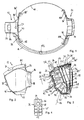
- Fig. 2
- eine Seitenansicht eines Leuchtenkopfs der mobilen Leuchte in Fig. 1,
- Fig. 3
- eine schematische Schnittansicht durch den Leuchtenkopf in Fig. 2,
- Fig. 4
- eine Draufsicht auf einen Tubenkörper des Leuchtenkopfs,
- Fig. 5
- eine Seitenansicht des Leuchtenkopfs in Fig. 2 mit einem ausgeschwenkten Stützelement,
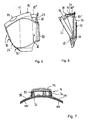
- Fig. 6
- eine schematische Schnittansicht durch eine Gehäuserückwand und das Stützelement des Leuchtenkopf in Fig. 5,
- Fig. 7
- eine schematische Schnittansicht durch einen Batteriebehälter Leuchte in Fig. 1,
- Fig. 8A, B, C
- eine schematische Schnittansicht durch den nur teilweise dargestellten Leuchtenkopf in Fig. 2 mit einem Strahlenverlauf von von dem Leuchtenkopf abgebbarem Licht, und Formen von Lichtflecken, die entstehen, wenn Lichtbündel in Fig. 8A auf in Fig. 8A gezeigte Flächen treffen.
- Fig. 1
- 2 shows a plan view of a mobile lamp according to a preferred embodiment of the invention in the form of a headlamp,
- Fig. 2
- 2 shows a side view of a lamp head of the mobile lamp in FIG. 1,
- Fig. 3
- 2 shows a schematic sectional view through the lamp head in FIG. 2,
- Fig. 4
- a plan view of a tube body of the lamp head,
- Fig. 5
- 3 shows a side view of the lamp head in FIG. 2 with a pivoted out support element,
- Fig. 6
- 5 shows a schematic sectional view through a rear wall of the housing and the support element of the lamp head in FIG. 5,
- Fig. 7
- 1 shows a schematic sectional view through a battery container light in FIG. 1,
- 8A, B, C
- 3 shows a schematic sectional view through the only partially illustrated lamp head in FIG. 2 with a beam path of light emittable by the lamp head, and shapes of light spots that arise when light beams in FIG. 8A strike surfaces shown in FIG. 8A.
In Fig. 1 umfasst eine als Stirnleuchte ausgebildete mobile Leuchte nach
einer bevorzugten Ausführungsform der Erfindung einen an einem elastischen,
stark dehnbaren Kopfband 10 gehaltenen Leuchtenkopf 12, einen
Batteriebehälter 14 sowie ein ebenfalls an dem Kopfband 10 gehaltenes
Verbindungskabel 16, das den Batteriebehälter 14 mit dem Leuchtenkopf
12 verbindet und zur Stromversorgung des Leuchtenkopfs 12 durch in
dem Batteriebehälter 14 gehaltene Batterien oder Akkus dient.1 comprises a mobile lamp designed as a headlight
a preferred embodiment of the invention one on an elastic,
highly
Der in den Fig. 2, 3, 5 und 6 genauer gezeigte Leuchtenkopf 12 umfasst
ein im Folgenden als Leuchtenkopfgehäuse bezeichnetes Gehäuse 18 mit
einem Gehäusevorderteil 20 und einer Gehäuserückwand 22, ein an dem
Leuchtenkopfgehäuse 18 bzw. dessen Gehäuserückwand 22 schwenkbar
gelagertes Stützelement 24 und einen im Bereich der Gehäuserückwand
22 und des Stützelements 24 offenen, sonst aber das Leuchtenkopfgehäuse
18 umschließenden Mantel 26, der im Folgenden als Leuchtenkopfgehäusemantel
bezeichnet wird.The
In dem Leuchtenkopfgehäuse 18 sind auf einer ersten Platine 28 drei
nicht alle in den Figuren sichtbare erste Leuchtdiodenelemente 30 für
weißes Licht und auf einer zweiten Platine 32 zwei nicht alle in den Figuren
sichtbare zweite Leuchtdiodenelemente 34 für weißes Licht sowie
entsprechende Versorgungsschaltungen für die Leuchtdiodenelemente
angeordnet. Die Leuchtdiodenelemente 30 und 34 greifen teilweise in
einen in dem Leuchtenkopfgehäuse 18 befestigten Tubenkörper 36. In the
Das Gehäusevorderteil 20 aus einem transparenten thermoplastischen
Kunststoff wie zum Beispiel Polycarbonat weist eine Vorderwand 38 mit
einem oberen ebenen Abschnitt 40 und einem unteren ebenen Abschnitt
40', der in einem vorgegebenen Winkel von im Beispiel etwa 45° in Richtung
auf die Gehäuserückwand 22 zu abgewinkelt ist, auf.The housing front part 20 made of a transparent thermoplastic
Plastic, such as polycarbonate, has a
In dem oberen Abschnitt 40 der Vorderwand 38 sind drei an den Ecken
eines gleichseitigen Dreiecks angeordnete erste Sammellinsen 42 gleicher
Brennweite und in dem unteren Abschnitt 40' weiterhin zwei nebeneinander
liegende zweite Sammellinsen 44, deren jeweils gleiche Brennweite
sich von der der ersten Sammellinsen 42 unterscheidet, ausgebildet. Die
optischen Achsen der ersten Sammellinsen 42 verlaufen mit gleichen,
geringen vorgegebenen ersten Neigungswinkeln gegenüber einer Senkrechten
auf die Ebene des Abschnitts 40 aufeinander zu. Ähnlich sind die
optischen Achsen der zweiten Sammellinsen 44 mit jeweils gleichen,
geringen, vorgegebenen zweiten Neigungswinkeln gegenüber einer Senkrechten
aufeinander zu geneigt, wobei eine durch die optischen Achsen
aufgespannte Ebene im Wesentlichen orthogonal zu der Ebene des Abschnitts
40' orientiert ist.In the
Der einstückige Tubenkörper 36 (vgl. Fig. 4) weist eine Grundplatte 46
auf, die ebenfalls einen oberen Abschnitt 48 und einen unteren, gegenüber
dem oberen Abschnitt 48 ebenfalls um den vorgegebenen Winkel, im
Beispiel also etwa 45°, abgewinkelten unteren Abschnitt 48' umfasst. Auf
dem oberen Abschnitt 48 sind drei erste Tuben 50 angeordnet, deren
Längsachsen orthogonal zu dem oberen Abschnitt 40 der Vorderwand
durch die Mittelpunkte der entsprechenden ersten Sammellinsen 42
verlaufen und die an der Vorderwand 38 anliegen, wenn der Tubenkörper
36 in das Leuchtenkopfgehäuse 18 eingesetzt ist. Auf dem unteren Bereich
der Grundplatte 46 sind zwei zweite Tuben 52 angeordnet, deren
Längsachsen im eingebauten Zustand der Tubenkörper 36 orthogonal zu
dem unteren Abschnitt 40' der Vorderwand durch die Mittelpunkte der
entsprechenden zweiten Sammellinsen 42 verlaufen und die an der Vorderwand
38 anliegen.The one-piece tube body 36 (cf. FIG. 4) has a
Die ersten und zweiten Tuben 50 und 52 sind auf ihrer Innenseite
schwarz und mattiert und weisen gleich Länge auf. Sie münden jeweils in
entsprechenden Öffnungen in der Grundplatte 46, die zusammen mit den
entsprechenden Enden der Tuben 50 und 52 Aufnahmen für Leuchtkörper
der Leuchtdiodenelemente 30 bzw. 34 bilden. Die erste Platine 28
und die zweite Platine 32 sind an der Grundplatte 46 befestigt, wobei die
entsprechenden Leuchtdiodenelemente 30 bzw. 34 im Wesentlichen formschlüssig
in den entsprechenden ersten Tuben 50 bzw. zweiten Tuben 52
angeordnet und durch diese mit ihren Längsachsen und damit Abstrahlrichtungen
parallel zueinander ausgerichtet sind.The first and
Von den Leuchtdiodenelementen 30 bzw. 34 abgegebenes Licht wird durch
die entsprechenden Tuben 50 bzw. 52 und die so den Leuchtdiodenelementen
jeweils zugeordneten Sammellinsen 42 bzw. 44 geführt und bildet
erste bzw. zweite abgegebene Lichtbündel 54 bzw. 56. Die ersten Leuchtdiodenelemente
30 und die ersten Sammellinsen 42 als erste abbildende
Einrichtungen bilden daher eine erste Leuchteinheit 58, während die
zweiten Leuchtdiodenelemente 34 zusammen mit den zweiten Sammellinsen
44 als zweiten abbildenden Einrichtungen eine zweite Leuchteinheit
60 darstellen, die gegenüber der ersten Leuchteinheit 58 in dem vorgegebenen
Winkel von im Beispiel etwa 45° angeordnet ist. Light emitted by the light emitting
Ein teilweise in einer Schalteröffnung 62 auf einer Oberseite des Gehäusevorderteils
22 angeordneter Schalter 64 bildet zusammen mit entsprechenden
Schaltungen auf der ersten Platine 28 und der zweiten Platine 32
eine Schalteinrichtung, mittels derer entweder nur die ersten Leuchtdiodenelemente
30 und damit die Leuchteinheit 58 oder nur die zweiten
Leuchtdiodenelemente 34 und damit die Leuchteinheit 60 oder auch beide
Leuchtdiodenelemente 30 und 34 und damit die Leuchteinheit 58 und 60
gemeinsam ein- bzw. ausgeschaltet werden können.One partially in a switch opening 62 on an upper side of the
Das Stützelement 24 ist flächig ausgebildet und mittels Lageraugen 66 auf
entsprechenden Lagerzapfen 68 an der Gehäuserückwand 22 des Leuchtenkopfgehäuses
18 um eine entsprechende Achse in einer im Wesentlichen
zu einer Ebene des Stützelements orthogonalen Ebene schwenkbar
gelagert (vgl. Fig. 2 und 3 bzw. Fig. 5 und 6).The
Weiterhin ist auf einer dem Leuchtenkopfgehäuse 18 abgewandten Seite
des Stützelements 24 eine Anlagefläche 70 ausgebildet, die beim Tragen
der Stirnlampe an einer Stirn eines Benutzers anliegt, wenn dieser das
elastische Kopfband 10 über seinen Kopf gestreift hat.Furthermore, is on a side facing away from the
Zur Sicherung des Stützelements 24 in einer eingestellten Schwenklage
gegenüber der Gehäuserückwand 22 sind an dem Stützelement 24 eine
kreissegmentförmig gewölbte Zahnstange 72 mit Rastzähnen 74 als Rastelementen
und an der Gehäuserückwand 22 ein federnder, an dem freien
Ende hakenförmigen Rastarm 76 mit einem Endvorsprung 78 mit einer
Rastöffnung für die Rastzähne 74 als komplementäres Rastelement angeordnet.
Die Zahnstange 72 ist so gewölbt und relativ zu dem Rastarm 76
so angeordnet, dass die Zahnstange 72 durch die Rastöffnung in dem
Endvorsprung 78 greift und eine Unterkante der Rastöffnung durch eine
Vorspannung des federnden Rastarms 76 in die Lücken zwischen den
Rastzähnen 74 einrastbar ist. Eine Bewegung des Stützelements 24 gegenüber
der Gehäuserückwand 22 wird so verhindert. Durch Druck auf
den Endvorsprung 78 mit der Rastöffnung ist der federnde Rastarm 76
von der Zahnstange 72 weg bewegbar, so dass die Zahnstange 72 in der
Rastöffnung verschiebbar und das Stützelement 24 gegenüber der Gehäuserückwand
22 schwenkbar ist (vgl. Fig. 5 und 6).To secure the
An dem Stützelement 24 sind weiterhin seitliche kreissektorartige Abdeckwände
80 und 80' und eine obere Abdeckwand 80" vorgesehen (vgl.
Fig. 3 und 6).Lateral circular sector-like cover walls are also on the
Das Stützelement 24 weist darüber hinaus in den Figuren nicht gezeigte
Schlitze auf, durch die das Kopfband 10 mit seinen Enden führbar und
durch Zurückfalten und Vernähen befestigbar ist.The
Der das Leuchtenkopfgehäuse 18 teilweise umschließende Leuchtenkopfgehäusemantel
26 ist aus einem thermoplastischen, elastomeren Material,
z.B. einem entsprechenden Polyurethanpolymer, gebildet. Auf einem an
der Vorderwand 38 anliegenden Bereich des Leuchtenkopfgehäusemantels
26 sind den ersten und zweiten Sammellinsen 42 bzw. 44 entsprechende
Öffnungen 82 und 82' ausgebildet, sodass Licht durch diese abstrahlbar
ist. Bis auf diese Öffnungen 82 und 82' und eine Öffnung im Bereich des
Stützelements 24 umschließt der Leuchtenkopfgehäusemantel 26 das
Gehäuse 18 vollständig.The lamp head housing jacket partially enclosing the
Der Leuchtenkopfgehäusemantel 26 erstreckt sich über die Gehäuserückwand
22 hinaus bis zu einem umlaufenden Außenrand des Stützelements
24, wenn dieses an die Gehäuserückwand 22 geschwenkt ist. Die
Abdeckwände 80, 80' und 80" sind so geformt, dass sie zusammen mit
dem Leuchtenkopfgehäusemantel 26 einen zwischen dem Stützelement 24
und der Gehäuserückwand 22 gebildeten Hohlraum im Wesentlichen
abdecken (vgl. Fig. 2 und 5). Dabei liegen die seitlichen Abdeckwände 80
und 80' mit ihren Stirnflächen an der Gehäuserückwand 22 an, wenn das
Stützelement 24 an die Gehäuserückwand 22 geschwenkt ist (vgl. Fig. 3).The lamp
Da der Leuchtenkopfgehäusemantel 26 aus einem elastomeren Material
gebildet ist, können durch entsprechende Ausbeulungen 84 und 84' der
Schalter 64 und der Endvorsprung 78 mit der Rastöffnung bedient werden.Since the lamp
Der Leuchtenkopfgehäusemantel 26 dient weiterhin zur Abdichtung des
Leuchtenkopfgehäuses 18, da er an diesem eng anliegt und so ein Eindringen
von Wasser zwischen den Leuchtenkopfgehäusemantel 26 und
das Leuchtenkopfgehäuse 18 weitgehend verhindert. Dadurch kann auch
kein Wasser zwischen dem Gehäusevorderteil 20 und der Gehäuserückwand
22 hindurch oder durch die Schalteröffnung 62 in das Innere des
Leuchtenkopfgehäuses 18 eindringen.The lamp
Weiterhin setzt sich der Leuchtenkopfgehäusemantel 26 seitlich des
Leuchtenkopfgehäuses 18 in zwei flexible Laschen 86 und 86' fort, die an
ihren Enden jeweils Schlaufen 88 und 88' mit schlitzförmigen Öffnungen
aufweisen, deren Höhe der Breite des Kopfbandes 10 entspricht und
durch die das Kopfband 10 führbar ist. Die Laschen 86 und 86' sind so
flexibel (vgl. Fig. 1), dass sie durch Zug an dem Kopfband 10, wie er beim
Aufsetzen der Stirnlampe auf einen Kopf auftritt, an den Kopf gezogen
werden können, und an diesem anliegen. Dadurch ergibt sich eine vergleichsweise
große Anlagefläche der erfindungsgemäßen Stirnleuchte an
dem Kopf, wodurch zum einen Druckstellen vermieden werden und zum
andere aufgrund der großen, sich auch weit zu den Seiten hin erstreckenden
Anlagefläche ein besonders sicherer Sitz gewährleistet wird.Furthermore, the lamp
Der in Fig. 7 genauer gezeigte Batteriebehälter 14 weist ein Gehäuse aus
einem thermoplastischen Kunststoff mit einem Batteriegehäuseunterteil
90 mit einem Batteriefach 92 und mit einem schwenkbar mit dem Batteriegehäuseunterteil
90 verbundenen Batteriebehälterdeckel 94 auf. Das
Batteriegehäuseunterteil 90 ist in analoger Weise wie das Leuchtenkopfgehäuse
18 des Leuchtenkopfs 12 in einem Mantel 96 aus einem elastomeren
thermoplastischen Material, im Folgenden als Batteriegehäusemantel
bezeichnet, teilweise umschlossen, der wie der Leuchtenkopfgehäusemantel
26 zwei Laschen 98 und 98' aufweist, an deren freien Enden
Schlaufen 100 und 100' zur Aufnahme des Kopfbandes 10 vorgesehen
sind, die wie die Schlaufen 86 und 86' ausgebildet sind. Ein dem Batteriebehälterdeckel
94 zugewandter Rand des Batteriegehäusemantels 96 dient
gleichzeitig als Dichtung zur Abdichtung eines möglicherweise auftretenden
Spalts zwischen dem Batteriegehäuseunterteil 90 und dem Batteriebehälterdeckel
94.The
Das in Fig. 1 nur schematisch gezeigte, über einen Klemmhalter 102 an
dem Kopfband 10 gehaltene Verbindungskabel 16 weist zwei mit entsprechenden
Polen des Batteriefachs 92 in dem Batteriebehälter 14 verbundene
Adern auf, die mit entsprechenden Kontakten auf den ersten und
zweiten Platinen 28 und 32 verbunden sind. Das Verbindungskabel 16
kann dabei insbesondere einen gewendelten Teilbereich aufweisen, so
dass der Batteriebehälter an dem Kopfband 10 verschiebbar ist. That shown only schematically in FIG. 1, via a clamp holder 102
the
Zur Herstellung des Leuchtenkopfs 12 können das Gehäusevorderteil 20
zusammen mit dem Leuchtenkopfgehäusemantel 26 und das Batteriegehäuseunterteil
90 mit dem Batteriebehälterdeckel 94 zusammen mit dem
Batteriegehäusemantel 96 durch Zwei-Komponenten-Spritzguss hergestellt
werden. Danach kann der Tubenkörper 36 in das Gehäusevorderteil
20 eingelegt und darin befestigt werden, woraufhin die erste und zweite
Platine 28 bzw. 32 mit den ersten Leuchtdiodenelementen 30 bzw. zweiten
Leuchtdiodenelementen 34 in die Grundplatte 46 mit den Tuben 50 bzw.
52 geschoben und an der Grundplatte 46 befestigt wird. Sodann kann die
Gehäuserückwand 22 mit dem daran gehaltenen Stützelement 24 an die
Gehäuserückwand 22 angeschraubt werden.The housing front part 20 can be used to produce the
Der Strahlengang des von den Leuchtdiodenelementen 30 bzw. 34 abgegebenen
Lichts ist ausführlicher schematisch in Fig. 8A gezeigt.The beam path of the emitted by the light emitting
Die ersten Leuchtdiodenelemente 30 erzeugen erste Leuchtdiodenelementlichtbündel
mit im Wesentlichen parallelen Abstrahlrichtungen, von denen
in Fig. 8A nur die Leuchtdiodenelementlichtbündel 104 und 104' sichtbar
sind und deren Öffnungswinkel und Richtung nach Passieren der ersten
Tuben 50 von den ersten abbildenden Einrichtungen, d.h. den ersten
Sammellinsen 42, geändert wird, wenn sie diese durchlaufen. Aus den so
gebildeten ersten Leuchtdiodenelementlichtbündeln wird das erstes Lichtbündel
54 der ersten Leuchteinheit 58 gebildet. Da zum einen die optischen
Achsen der ersten Sammellinsen 42 mit gleichen Winkeln gegenüber
der Senkrechten auf den Abschnitt 40 aufeinander zu geneigt sind
und die ersten Leuchtdiodenelemente 30 an den Ecken eines gleichseitigen
Dreiecks mit zueinander im Wesentlichen parallelen Abstrahlrichtungen
angeordnet sind, ergibt sich damit eine in Fig. 8A von rechts nach
links verlaufende erste Abstrahlrichtung A der ersten Leuchteinheit 58,
die im Wesentlichen orthogonal zu dem oberen Abschnitt 40 der Vorderwand
38 des Leuchtenkopfgehäuses 18 ausgerichtet ist.The first light-emitting
Die Neigung der optischen Achsen der ersten Sammellinsen 42 zueinander
und gegenüber einer Senkrechten auf den Abschnitt 40 ist so gewählt,
dass die durch die Sammellinsen 42 gebündelten, von den ersten Leuchtdiodenelementen
30 abgegebenen ersten Leuchtdiodenelementlichtbündel
104 und 104' sich in einer Entfernung von etwa 60 cm von der Lampe zu
überschneiden beginnen und sich in einer Entfernung von etwa 10 m
vollständig überschneiden. Bei Beleuchtung einer zur der Abstrahlrichtung
A orthogonalen Fläche 106 im Abstand von etwa 10 m, die in Fig. 8A
nicht maßstabsgetreu gezeigt ist, ergibt sich, wie in Fig. 8B gezeigt, ein im
Wesentlichen kreisförmiger Lichtfleck 108 mit einem Flächeninhalt von ca.
2,5m2, der dem der Querschnittsfläche des ersten Lichtbündels 54 in
diesem Abstand entspricht. Der in der Fig. 8A gezeigte Öffnungswinkel des
durch die Leuchtdiodenelementlichtbündel der drei Leuchtdiodenelemente
30 gebildeten ersten Lichtbündels 54 ist übertrieben groß gezeichnet.The inclination of the optical axes of the first converging
Das erste Lichtbündel 54 eignet sich daher zur Beleuchtung eines entfernten
Raumbereichs.The
Die zweiten Leuchtdiodenelemente 34 erzeugen zweite Leuchtdiodenelementlichtbündel
mit im Wesentlichen parallelen Abstrahlrichtungen, von
denen in Fig. 8A nur das Leuchtdiodenelementlichtbündel 110 sichtbar ist
und deren Öffnungswinkel und Richtung nach Passieren der zweiten
Tuben 52 von den zweiten abbildenden Einrichtungen, d.h. den zweiten
Sammellinsen 44, geändert wird, wenn sie diese durchlaufen. Aus den so
gebildeten zweiten Leuchtdiodenelementlichtbündeln wird das zweite
Lichtbündel 56 der zweiten Leuchteinheit 60 gebildet. Da zum einen die
optischen Achsen der zweiten Sammellinsen 44 mit gleichen Winkeln
gegenüber der Senkrechten auf den unteren Abschnitt 40' aufeinander zu
geneigt sind und die zweiten Leuchtdiodenelemente 34 in einer Richtung
parallel zu einer Kante zwischen den Abschnitten 40 und 40' mit zueinander
im Wesentlichen parallelen Abstrahlrichtungen angeordnet sind,
ergibt sich damit eine zweite Abstrahlrichtung A' der zweiten Leuchteinheit
60, die im Wesentlichen orthogonal zu dem unteren Abschnitt 40' der
Vorderwand 38 des Leuchtenkopfgehäuses 18 ausgerichtet ist und damit
mit der ersten Abstrahlrichtung A einen dem vorgegebenen Winkel zwischen
den Abschnitten 40 und 40' entsprechenden Winkel von im Beispiel
etwa 45° einschließen. Das erste und das zweite Lichtbündel 54 und 56
überschneiden sich daher nicht, so dass mit ihnen voneinander verschiedene
Raumbereiche, die sich nicht überschneiden, beleuchtbar sind.The second light-emitting
Die Neigung der optischen Achsen der zweiten Sammellinsen 42 zueinander
und gegenüber einer Senkrechten auf den unteren Abschnitt 40' ist so
gewählt, dass sich die durch die zweiten Sammellinsen 44 gebündelten,
von den zweiten Leuchtdiodenelementen 34 abgegebenen zweiten Leuchtdiodenelementlichtbündel
110 in einer Entfernung von etwa 1 m von der
Leuchte vollständig überschneiden. Wie in Fig. 8A schematisch gezeigt
ergibt sich bei Beleuchtung einer zur der zweiten Abstrahlrichtung A'
orthogonalen Fläche 112 ein im Wesentlichen kreisförmiger Lichtfleck mit
einem Flächeninhalt von ca.0,75 m2, der dem der Querschnittsfläche des
zweiten Lichtbündels 56 in diesem Abstand entspricht. Die Querschnittsfläche
des ersten Lichtbündels ist daher in 1m Abstand kleiner als die des
zweiten Lichtbündels.The inclination of the optical axes of the second converging
Auf einer gegenüber der ersten Ausbreitungsrichtung A senkrechten
Fläche 116 ergibt das zweite Lichtbündel 56 dann einen im Wesentlichen
ovalen Lichtfleck 114, der in dieser Entfernung scharf abgegrenzt ist (vgl.
Fig. 8C).On a perpendicular to the first direction of
Das zweite Lichtbündel 56 kann daher als Nahlicht zur Beleuchtung von
Gegenständen im Bereich der Hände eines Benutzers der Stirnlampe
verwendet werden.The second
Durch die Schwenkbarkeit des Stützelements 24 kann die Neigung des
Leuchtenkopfs 12 und damit die der ersten und zweiten Abstrahlrichtungen
A und A' dabei an die Neigung der Stirn eines Trägers angepasst
werden. Due to the pivotability of the
- 1010
- Kopfbandheadband
- 1212
- Leuchtenkopflamp head
- 1414
- Batteriebehälterbattery container
- 1616
- Verbindungskabelconnection cable
- 1818
- LeuchtenkopfgehäuseLamp head housing
- 2020
- GehäusevorderteilFront housing
- 2222
- GehäuserückwandRear panel
- 2424
- Stützelementsupport element
- 2626
- LeuchtenkopfgehäusemantelLamp head housing jacket
- 2828
- erste Platinefirst board
- 3030
- erste Leuchtdiodenelementefirst light emitting diode elements
- 3232
- zweite Platinesecond board
- 3434
- zweite Leuchtdiodenelementesecond light emitting diode elements
- 3636
- Tubenkörpertube body
- 3838
- Vorderwandfront wall
- 40, 40'40, 40 '
- oberer und untere Abschnittupper and lower section
- 4242
- erste Sammellinsenfirst converging lenses
- 4444
- zweite Sammellinsensecond converging lenses
- 4646
- Grundplattebaseplate
- 48, 48'48, 48 '
- oberer und unterer Abschnittupper and lower section
- 5050
- erste Tubenfirst tubes
- 5252
- zweite Tubensecond tubes
- 5454
- Lichtbündellight beam
- 5656
- Lichtbündellight beam
- 5858
- erste Leuchteinheitfirst lighting unit
- 6060
- zweite Leuchteinheitsecond light unit
- 6262
- Schalteröffnung.Office opening.
- 6464
- Schalter switch
- 6666
- Lageraugenbearing eyes
- 6868
- Lagerzapfenpivot
- 7070
- Anlageflächecontact surface
- 7272
- Zahnstangerack
- 7474
- Rastzähnelocking teeth
- 7676
- Rastarmdetent arm
- 7878
- Endvorsprungend projection
- 80, 80', 80"80, 80 ', 80 "
- Abdeckwändecovering walls
- 82, 82'82, 82 '
- Öffnungenopenings
- 84,84'84.84 '
- Ausbeulungenbulges
- 86, 86'86, 86 '
- Laschentabs
- 88, 88'88, 88 '
- Schlaufenloops
- 9090
- BatteriegehäuseunterteilBattery housing base
- 9292
- Batteriefachbattery
- 9494
- BatteriebehälterdeckelBattery container cover
- 9696
- BatteriegehäusemantelBattery housing jacket
- 98,98'98.98 '
- Laschentabs
- 100, 100'100, 100 '
- Schlaufenloops
- 102102
- KlemmhalterTool holders
- 104, 104'104, 104 '
- erste Leuchtdiodenelementlichtbündelfirst light emitting diode element bundle
- 106106
- Flächearea
- 108108
- Lichtflecklight spot
- 110110
- zweites Leuchtdiodenelementlichtbündelsecond light emitting diode element
- 112112
- Flächearea
- 114114
- Lichtflecklight spot
- 116116
- Flächearea
- AA
- erste Ausbreitungsrichtungfirst direction of propagation
- A'A '
- zweite Ausbreitungsrichtungsecond direction of propagation
Claims (19)
einer ersten Leuchteinheit (58) zur Abstrahlung eines ersten Lichtbündels (54) in einer ersten Abstrahlrichtung (A), die zur Bildung des ersten Lichtbündels (54) wenigstens ein erstes Leuchtdiodenelement (30) und eine dem ersten Leuchtdiodenelement (30) zugeordnete abbildende Einrichtung (42), der von dem ersten Leuchtdiodenelement (30) abgegebenes Licht zuführbar ist, aufweist, und
einer zweiten Leuchteinheit (60) zur Abstrahlung eines zweiten Lichtbündels (56) in einer zweiten, von der ersten Abstrahlrichtung abweichenden Abstrahlrichtung (A'), die zur Bildung des zweiten Lichtbündels (56) wenigstens ein zweites Leuchtdiodenelement (34) und eine dem zweiten Leuchtdiodenelement (34) zugeordnete abbildende Einrichtung (44), der von dem zweiten Leuchtdiodenelement (34) abgegebenes Licht zuführbar ist, aufweist.Mobile lamp with
a first lighting unit (58) for emitting a first light bundle (54) in a first radiation direction (A), which for forming the first light bundle (54) has at least one first light-emitting diode element (30) and an imaging device (30) assigned to the first light-emitting diode element (30) 42) which can be supplied with light emitted by the first light-emitting diode element (30), and
a second lighting unit (60) for emitting a second light bundle (56) in a second radiation direction (A ') which deviates from the first radiation direction and which forms at least one second light-emitting diode element (34) and one for the second light-emitting diode element to form the second light bundle (56) (34) has associated imaging device (44) which can be supplied with light emitted by the second light-emitting diode element (34).
dadurch gekennzeichnet, dass eine Schalteinrichtung (64) vorgesehen ist, mittels derer die Leuchteinheiten (558, 60) einzeln an- und ausschaltbar sind.Mobile light according to claim 1,
characterized in that a switching device (64) is provided, by means of which the lighting units (558, 60) can be switched on and off individually.
dadurch gekennzeichnet, dass die abbildenden Einrichtungen (42, 44) der beiden Leuchteinheiten (58, 60) in einem Bauteil (20) einstückig ausgebildet sind.Mobile light according to claim 1 or 2,
characterized in that the imaging devices (42, 44) of the two lighting units (58, 60) are integrally formed in one component (20).
dadurch gekennzeichnet, dass eine der Leuchteinheiten so relativ zu der anderen beweglich gelagert ist, dass der Winkel zwischen der ersten und der zweiten Abstrahlrichtung veränderbar ist.Mobile light according to claim 1 or 2,
characterized in that one of the lighting units is mounted so as to be movable relative to the other that the angle between the first and the second radiation direction can be changed.
dadurch gekennzeichnet, dass die zweite Abstrahlrichtung (A') mit der ersten Abstrahlrichtung (A) einen Winkel einschließt, der größer als 5° und kleiner als 85° ist.Mobile lamp according to one of the preceding claims,
characterized in that the second radiation direction (A ') forms an angle with the first radiation direction (A) which is greater than 5 ° and less than 85 °.
dadurch gekennzeichnet, dass die Leuchteinheiten (58, 60) so ausgebildet sind, dass die von den Leuchteinheiten (58, 60) abstrahlbaren Lichtbündel (54, 56) divergent sind und eine Querschnittsfläche des ersten Lichtbündels (54) in einer vorgegebenen Entfernung von der Leuchte kleiner ist als eine Querschnittsfläche des zweiten Lichtbündels (56) in der vorgegebenen Entfernung.Mobile lamp according to one of the preceding claims,
characterized in that the lighting units (58, 60) are designed such that the light bundles (54, 56) which can be emitted by the lighting units (58, 60) are divergent and a cross-sectional area of the first light bundle (54) at a predetermined distance from the light is smaller than a cross-sectional area of the second light bundle (56) at the predetermined distance.
dadurch gekennzeichnet, dass die wenigstens eine abbildende Einrichtung wenigstens einer der Leuchteinheiten ein fokussierendes optisches Bauelement umfasst und so ausgebildet ist, dass das Licht der entsprechenden Leuchteinheit in einer vorgegebenen Entfernung auf eine Fläche orthogonal zu der Abstrahlrichtung fokussierbar ist.Mobile lamp according to one of claims 1 to 5,
characterized in that the at least one imaging device of at least one of the lighting units comprises a focusing optical component and is designed such that the light of the corresponding lighting unit can be focused at a predetermined distance onto a surface orthogonal to the direction of radiation.
dadurch gekennzeichnet, dass die Leuchteinheiten (58, 60) so ausgebildet sind, dass mittels der ersten Leuchteinheit (58) auf einer orthogonal zu der ersten Ausbreitungsrichtung (A) orientierten ersten Fläche in etwa 10 m Entfernung ein Lichtfleck mit einem Flächeninhalt zwischen 1m2 und 4m2 und mittels der zweiten Leuchteinheit (60) auf einer orthogonal zu der zweiten Ausbreitungsrichtung orientierten zweiten Fläche in etwa 1 m Entfernung ein Lichtfleck (114) mit einem Flächeninhalt zwischen 0,4m2 und 2m2 erzeugbar sindMobile lamp according to one of the preceding claims,
characterized in that the lighting units (58, 60) are designed such that by means of the first lighting unit (58) on a first surface oriented orthogonally to the first direction of propagation (A) at a distance of approximately 10 m a light spot with an area between 1m 2 and 4m 2 and a light spot (114) with an area between 0.4m 2 and 2m 2 can be generated by means of the second lighting unit (60) on a second surface oriented orthogonally to the second direction of propagation at about 1 m distance
dadurch gekennzeichnet, dass die abbildenden Einrichtungen von den Leuchtdiodenelementen beabstandete Linsen (42, 44) umfassen.Mobile lamp according to one of the preceding claims,
characterized in that the imaging devices comprise lenses (42, 44) spaced from the light emitting diode elements.
dadurch gekennzeichnet, dass die erste und/oder zweite Leuchteinheit (58, 60) jeweils wenigstens zwei Leuchtdiodenelemente (30, 34) und wenigstens zwei entsprechende abbildende Einrichtungen (42, 44) umfassen.Mobile lamp according to one of the preceding claims,
characterized in that the first and / or second lighting unit (58, 60) each comprise at least two light-emitting diode elements (30, 34) and at least two corresponding imaging devices (42, 44).
dadurch gekennzeichnet, dass die abbildenden Einrichtungen (42, 44) von wenigstens zwei Leuchtdiodenelementen (30, 34) einer der Leuchteinheiten (58, 60) so ausgebildet sind, dass eine vorgegebene Fläche (106, 108) in einer vorgegebenen Entfernung von der mobilen Leuchte von Leuchtdiodenelementlichtbündeln (104, 104', 110) dieser Leuchtdiodenelemente (30, 40) beleuchtbar ist.Mobile lamp according to claim 10,
characterized in that the imaging devices (42, 44) of at least two light-emitting diode elements (30, 34) of one of the lighting units (58, 60) are designed such that a predetermined area (106, 108) is at a predetermined distance from the mobile lamp of light emitting diode element light bundles (104, 104 ', 110) of these light emitting diode elements (30, 40) can be illuminated.
dadurch gekennzeichnet, dass die Leuchtdiodenelemente (30, 34) Leuchtdiodenelemente zur Abgabe von im Wesentlichen weißem Licht sind.Mobile lamp according to one of the preceding claims,
characterized in that the light emitting diode elements (30, 34) are light emitting diode elements for emitting essentially white light.
dadurch gekennzeichnet, dass die Leuchte als Fahrzeugleuchte, insbesondere als Fahrradleuchte, ausgebildet ist.Mobile lamp according to one of the preceding claims,
characterized in that the lamp is designed as a vehicle lamp, in particular as a bicycle lamp.
dadurch gekennzeichnet, dass die Leuchte als Stirnlampe ausgebildet ist.Mobile lamp according to one of claims 1 to 12,
characterized in that the lamp is designed as a headlamp.
dadurch gekennzeichnet, dass die Leuchte ein flächiges Stützelement (24) aufweist, das relativ zu den Leuchteinheiten (58, 60) in einer Ebene schwenkbar ist, die im Wesentlichen parallel zu der ersten und zweiten Abstrahlrichtung (A, A') ausgerichtet ist.Mobile lamp according to one of the preceding claims,
characterized in that the lamp has a flat support element (24) which can be pivoted relative to the lamp units (58, 60) in a plane which is oriented essentially parallel to the first and second radiation directions (A, A ').
dadurch gekennzeichnet, dass ein Gehäuse (18) vorgesehen ist, in dem die Leuchteinheiten (58, 60) angeordnet sind, und
dass an dem Gehäuse (18) und an dem Stützelement (24) zueinander komplementäre Rastelemente (72, 74, 76, 78) angeordnet sind, mittels derer das Stützelement (24) in seiner Relativlage zu dem Gehäuse (18) sicherbar ist.Mobile light according to claim 15,
characterized in that a housing (18) is provided, in which the lighting units (58, 60) are arranged, and
that on the housing (18) and on the support element (24) mutually complementary locking elements (72, 74, 76, 78) are arranged, by means of which the support element (24) can be secured in its relative position to the housing (18).
ein Gehäuse (18) zur Aufnahme der Leuchteinheiten (58, 60), und zwei an sich gegenüberliegenden Seiten des Gehäuses (18) angeordnete, mit dem Gehäuse (18) verbundene Laschen (86, 86'), an denen ein elastisches Band (10) zur Befestigung der Leuchte an einem Gegenstand oder einem Kopf einer Person haltbar ist und die so flexibel sind, dass deren Form bei Befestigung an dem Gegenstand bzw. Kopf durch die Spannung des elastischen Bandes (10) an die Form des Gegenstands bzw. Kopfes anpassbar ist.Mobile lamp according to one of the preceding claims, characterized by
a housing (18) for receiving the lighting units (58, 60), and two tabs (86, 86 ') which are arranged on opposite sides of the housing (18) and are connected to the housing (18) and on which an elastic band (10 ) for attaching the lamp to an object or a head of a person and which are so flexible that their shape when attached to the object or head can be adapted to the shape of the object or head by the tension of the elastic band (10) is.
dadurch gekennzeichnet, dass die Leuchteinheiten in einem Gehäuse angeordnet sind, in dem ein Batteriefach vorgesehen ist.Mobile lamp according to one of the preceding claims,
characterized in that the lighting units are arranged in a housing in which a battery compartment is provided.
dadurch gekennzeichnet, dass die Leuchteinheiten (58, 60) in einem Gehäuse (18) an einem elastischen Band (10) gehalten sind, und
dass an dem Band (10) ein Batteriebehälter (14) gehalten ist.Mobile lamp according to one of the preceding claims,
characterized in that the lighting units (58, 60) are held in a housing (18) on an elastic band (10), and
that a battery container (14) is held on the belt (10).
Applications Claiming Priority (2)
| Application Number | Priority Date | Filing Date | Title |
|---|---|---|---|
| DE10254634A DE10254634A1 (en) | 2002-11-22 | 2002-11-22 | Mobile lamp |
| DE10254634 | 2002-11-22 |
Publications (2)
| Publication Number | Publication Date |
|---|---|
| EP1422468A2 true EP1422468A2 (en) | 2004-05-26 |
| EP1422468A3 EP1422468A3 (en) | 2007-02-28 |
Family
ID=32185910
Family Applications (1)
| Application Number | Title | Priority Date | Filing Date |
|---|---|---|---|
| EP03022811A Withdrawn EP1422468A3 (en) | 2002-11-22 | 2003-10-07 | Portabel lamp with light emitting diodes |
Country Status (4)
| Country | Link |
|---|---|
| US (1) | US20040141316A1 (en) |
| EP (1) | EP1422468A3 (en) |
| CA (1) | CA2450166A1 (en) |
| DE (2) | DE20221972U1 (en) |
Cited By (2)
| Publication number | Priority date | Publication date | Assignee | Title |
|---|---|---|---|---|
| DE102020001701A1 (en) | 2020-03-14 | 2021-09-16 | Volker Drollinger | Headlight and headlamp |
| DE102021131816B3 (en) | 2021-12-02 | 2023-04-27 | Jochen Klieber | Additional lighting device for a two-wheeler and two-wheeler with it |
Families Citing this family (34)
| Publication number | Priority date | Publication date | Assignee | Title |
|---|---|---|---|---|
| US6979099B2 (en) * | 2004-02-12 | 2005-12-27 | Brookstone Purchasing, Inc. | Portable lighting device with multi-activation switch |
| US7234833B2 (en) * | 2004-03-31 | 2007-06-26 | Richard Anthony Hatherill | Work light |
| US7452099B2 (en) * | 2005-01-21 | 2008-11-18 | Cyberlux Corporation | Portable light device |
| JP4173487B2 (en) * | 2005-01-31 | 2008-10-29 | 株式会社シマノ | Bicycle lighting device |
| US9526292B2 (en) | 2005-05-17 | 2016-12-27 | Michael Waters | Power modules and headgear |
| US7922353B2 (en) * | 2006-03-20 | 2011-04-12 | Larson Isely | Apparatus, method and system for providing multi-mode illumination |
| US20080084690A1 (en) * | 2006-09-19 | 2008-04-10 | Rappl Philip L | Universal walker headlight |
| DE212010000023U1 (en) | 2009-02-27 | 2012-01-24 | Michael Waters | Lighting headgear |
| NL2004331C2 (en) * | 2010-03-03 | 2011-09-06 | Stenman Holland Nv | BIKE LIGHT AND BIKE. |
| CA2797973A1 (en) | 2010-04-30 | 2011-11-03 | Michael Waters | Hands free lighting devices |
| US9500340B2 (en) | 2011-10-25 | 2016-11-22 | A-Dec, Inc. | Dental light using LEDs |
| US9526287B2 (en) | 2011-12-23 | 2016-12-27 | Michael Waters | Lighted hat |
| US9609902B2 (en) | 2011-12-23 | 2017-04-04 | Michael Waters | Headgear having a camera device |
| US9568173B2 (en) * | 2011-12-23 | 2017-02-14 | Michael Waters | Lighted hat |
| US9074739B2 (en) | 2012-01-06 | 2015-07-07 | Pelican Products, Inc. | Flashlight with multiple light sources |
| WO2014100477A1 (en) | 2012-12-19 | 2014-06-26 | Michael Waters | Lighted solar hat |
| GB2511077B (en) * | 2013-02-22 | 2015-06-24 | Wen-Sung Lee | High beam and low beam combination lamp for a bicycle |
| DE102013203103B4 (en) * | 2013-02-26 | 2018-05-09 | Osram Gmbh | Fixing element for a lighting device |
| US9717633B2 (en) | 2013-03-15 | 2017-08-01 | Michael Waters | Lighted headgear |
| US9752761B2 (en) | 2014-07-16 | 2017-09-05 | Telebrands Corp. | Landscape light |
| USD773707S1 (en) | 2014-10-30 | 2016-12-06 | Telebrands Corp. | Landscape light |
| USD766484S1 (en) | 2015-05-11 | 2016-09-13 | Telebrands Corp. | Light projector |
| USD766483S1 (en) | 2015-05-11 | 2016-09-13 | Telebrands Corp. | Light projector |
| USD816890S1 (en) | 2015-05-11 | 2018-05-01 | Telebrands Corp. | Light projector |
| USD824066S1 (en) | 2015-05-11 | 2018-07-24 | Telebrands Corp. | Light projector |
| USD778478S1 (en) | 2015-05-11 | 2017-02-07 | Telebrands Corp. | Light projector |
| US9879847B2 (en) * | 2015-12-03 | 2018-01-30 | Telebrands Corp. | Decorative lighting apparatus having two laser light sources |
| USD798484S1 (en) | 2016-09-29 | 2017-09-26 | Telebrands Corp. | Landscape light |
| USD797975S1 (en) | 2016-09-29 | 2017-09-19 | Telebrands Corp. | Landscape light |
| KR101896831B1 (en) * | 2017-03-24 | 2018-09-07 | 윤종구 | Intelligent headlight system for bicycles |
| RU2682316C1 (en) * | 2018-04-14 | 2019-03-19 | Закрытое акционерное общество "Производственное объединение "Электроточприбор" | Mine head lamp |
| NL2020781B1 (en) * | 2018-04-17 | 2019-10-24 | Vanmoof Bv | Bicycle with light system, bicycle tube cassette and working method |
| US10791783B1 (en) | 2019-05-16 | 2020-10-06 | Waters Industries, Inc. | Lighted headgear and accessories therefor |
| FR3107333B1 (en) * | 2020-02-14 | 2022-09-02 | Lagolight | Headlamp adjustable to the curvature of a user's skull |
Citations (5)
| Publication number | Priority date | Publication date | Assignee | Title |
|---|---|---|---|---|
| DE19909220A1 (en) * | 1999-03-03 | 2000-09-07 | Zedel Crolles | Portable electric double light |
| US6158874A (en) * | 1999-05-19 | 2000-12-12 | Brustein; Samuel | Multiple beam flashlight |
| EP1081425A2 (en) * | 1999-09-03 | 2001-03-07 | Zweibrüder Stahlwarenkontor GmbH | Flashlight |
| US20020149928A1 (en) * | 2001-04-13 | 2002-10-17 | Watterson Scott R. | Illumination device having multiple light sources |
| US20020159253A1 (en) * | 2001-04-26 | 2002-10-31 | Dalebout William T. | Attachable illumination device |
Family Cites Families (6)
| Publication number | Priority date | Publication date | Assignee | Title |
|---|---|---|---|---|
| US4638410A (en) * | 1981-02-23 | 1987-01-20 | Barker Randall R | Diving helmet |
| US5580156A (en) * | 1994-09-27 | 1996-12-03 | Koito Manufacturing Co., Ltd. | Marker apparatus |
| US6190020B1 (en) * | 1999-06-23 | 2001-02-20 | Fred Jack Hartley | Light producing assembly for a flashlight |
| FR2809796B1 (en) * | 2000-06-05 | 2002-07-12 | Zedel | PORTABLE LIGHTING LIGHT WITH LIGHT EMITTING DIODES |
| US6626555B2 (en) * | 2000-12-04 | 2003-09-30 | Rob Yaeger | Portable illumination device |
| US6877875B2 (en) * | 2002-11-06 | 2005-04-12 | Zen Design Group, Ltd | Canted head-mounted light |
-
2002
- 2002-11-22 DE DE20221972U patent/DE20221972U1/en not_active Expired - Lifetime
- 2002-11-22 DE DE10254634A patent/DE10254634A1/en not_active Withdrawn
-
2003
- 2003-10-07 EP EP03022811A patent/EP1422468A3/en not_active Withdrawn
- 2003-11-20 US US10/718,253 patent/US20040141316A1/en not_active Abandoned
- 2003-11-20 CA CA002450166A patent/CA2450166A1/en not_active Abandoned
Patent Citations (5)
| Publication number | Priority date | Publication date | Assignee | Title |
|---|---|---|---|---|
| DE19909220A1 (en) * | 1999-03-03 | 2000-09-07 | Zedel Crolles | Portable electric double light |
| US6158874A (en) * | 1999-05-19 | 2000-12-12 | Brustein; Samuel | Multiple beam flashlight |
| EP1081425A2 (en) * | 1999-09-03 | 2001-03-07 | Zweibrüder Stahlwarenkontor GmbH | Flashlight |
| US20020149928A1 (en) * | 2001-04-13 | 2002-10-17 | Watterson Scott R. | Illumination device having multiple light sources |
| US20020159253A1 (en) * | 2001-04-26 | 2002-10-31 | Dalebout William T. | Attachable illumination device |
Cited By (4)
| Publication number | Priority date | Publication date | Assignee | Title |
|---|---|---|---|---|
| DE102020001701A1 (en) | 2020-03-14 | 2021-09-16 | Volker Drollinger | Headlight and headlamp |
| WO2021185396A1 (en) | 2020-03-14 | 2021-09-23 | Drollinger Volker | Headlight and headlamp |
| DE102020001701B4 (en) | 2020-03-14 | 2022-09-08 | Volker Drollinger | headlights and headlamps |
| DE102021131816B3 (en) | 2021-12-02 | 2023-04-27 | Jochen Klieber | Additional lighting device for a two-wheeler and two-wheeler with it |
Also Published As
| Publication number | Publication date |
|---|---|
| DE10254634A1 (en) | 2004-06-03 |
| EP1422468A3 (en) | 2007-02-28 |
| CA2450166A1 (en) | 2004-05-22 |
| US20040141316A1 (en) | 2004-07-22 |
| DE20221972U1 (en) | 2010-03-25 |
Similar Documents
| Publication | Publication Date | Title |
|---|---|---|
| EP1422468A2 (en) | Portabel lamp with light emitting diodes | |
| EP1422467A2 (en) | Mobile lamp | |
| DE60037427T2 (en) | ILLUMINATION DEVICE | |
| DE4342928C2 (en) | Reflector arrangement with a light source arranged therein for a vehicle lamp | |
| EP1392999B1 (en) | Pocket lamp | |
| DE102005015077B4 (en) | Vehicle headlights and automobile headlights | |
| DE102006044019B4 (en) | reflector spotlight | |
| DE212010000023U1 (en) | Lighting headgear | |
| DE102007010419B4 (en) | illuminated vanity mirrors | |
| DE19853402B4 (en) | Headlamp with hyperbolic reflector and headlamp insert with such a headlamp | |
| EP0157356A2 (en) | Pocket lamp | |
| DE10144637A1 (en) | vehicle lamp | |
| DE20221973U1 (en) | headlamp | |
| DE202009007455U1 (en) | Indicator lamp for bicycle | |
| DE102017101949A1 (en) | lighting device | |
| EP1085253A2 (en) | Lamp, in particular for motor vehicles | |
| WO2012079770A1 (en) | Device for interior lighting in a motor vehicle | |
| DE202015009650U1 (en) | Double Focus Flashlight | |
| EP1647762A2 (en) | Halogen rechargeable lamp with LED's and fluorescent light | |
| EP2264362A1 (en) | LED headlamp and illumination system with such a headlamp | |
| DE10328576A1 (en) | Mobile light, e.g. torch, has switching device with which LED element(s) of one light arrangement can be switched on and off separately from that or those of the other light arrangement | |
| EP1081425A2 (en) | Flashlight | |
| DE102013006320A1 (en) | Operating light with LED light guide and focusing device and method for this purpose | |
| DE102013210856A1 (en) | Luminaire for a motor vehicle | |
| DE19941987A1 (en) | Torch has first light source, hollow reflector in housing, high power LED on annular casing of lamp head whose light cone is radiated essentially in radial direction with respect to lamp head |
Legal Events
| Date | Code | Title | Description |
|---|---|---|---|
| PUAI | Public reference made under article 153(3) epc to a published international application that has entered the european phase |
Free format text: ORIGINAL CODE: 0009012 |
|
| AK | Designated contracting states |
Kind code of ref document: A2 Designated state(s): AT BE BG CH CY CZ DE DK EE ES FI FR GB GR HU IE IT LI LU MC NL PT RO SE SI SK TR |
|
| AX | Request for extension of the european patent |
Extension state: AL LT LV MK |
|
| PUAL | Search report despatched |
Free format text: ORIGINAL CODE: 0009013 |
|
| AK | Designated contracting states |
Kind code of ref document: A3 Designated state(s): AT BE BG CH CY CZ DE DK EE ES FI FR GB GR HU IE IT LI LU MC NL PT RO SE SI SK TR |
|
| AX | Request for extension of the european patent |
Extension state: AL LT LV MK |
|
| AKX | Designation fees paid | ||
| STAA | Information on the status of an ep patent application or granted ep patent |
Free format text: STATUS: THE APPLICATION IS DEEMED TO BE WITHDRAWN |
|
| 18D | Application deemed to be withdrawn |
Effective date: 20070829 |
|
| REG | Reference to a national code |
Ref country code: DE Ref legal event code: 8566 |