EP1422416B1 - Brennkraftmaschine, sowie Verfahren zum Betreiben einer Brennkraftmaschine - Google Patents
Brennkraftmaschine, sowie Verfahren zum Betreiben einer Brennkraftmaschine Download PDFInfo
- Publication number
- EP1422416B1 EP1422416B1 EP03012486A EP03012486A EP1422416B1 EP 1422416 B1 EP1422416 B1 EP 1422416B1 EP 03012486 A EP03012486 A EP 03012486A EP 03012486 A EP03012486 A EP 03012486A EP 1422416 B1 EP1422416 B1 EP 1422416B1
- Authority
- EP
- European Patent Office
- Prior art keywords
- combustion engine
- starter motor
- internal combustion
- electric starter
- fuel pump
- Prior art date
- Legal status (The legal status is an assumption and is not a legal conclusion. Google has not performed a legal analysis and makes no representation as to the accuracy of the status listed.)
- Expired - Lifetime
Links
- 238000002485 combustion reaction Methods 0.000 title claims description 77
- 238000000034 method Methods 0.000 title claims description 19
- 239000000446 fuel Substances 0.000 claims description 143
- 239000007858 starting material Substances 0.000 claims description 64
- 238000002347 injection Methods 0.000 claims description 5
- 239000007924 injection Substances 0.000 claims description 5
- 230000005540 biological transmission Effects 0.000 description 7
- 238000000889 atomisation Methods 0.000 description 5
- 230000001105 regulatory effect Effects 0.000 description 5
- 230000008878 coupling Effects 0.000 description 4
- 238000010168 coupling process Methods 0.000 description 4
- 238000005859 coupling reaction Methods 0.000 description 4
- 238000011161 development Methods 0.000 description 2
- 230000018109 developmental process Effects 0.000 description 2
- 239000002828 fuel tank Substances 0.000 description 2
- 238000004590 computer program Methods 0.000 description 1
- 230000000694 effects Effects 0.000 description 1
- 230000006870 function Effects 0.000 description 1
- 238000012544 monitoring process Methods 0.000 description 1
Images

Classifications
-
- F—MECHANICAL ENGINEERING; LIGHTING; HEATING; WEAPONS; BLASTING
- F02—COMBUSTION ENGINES; HOT-GAS OR COMBUSTION-PRODUCT ENGINE PLANTS
- F02N—STARTING OF COMBUSTION ENGINES; STARTING AIDS FOR SUCH ENGINES, NOT OTHERWISE PROVIDED FOR
- F02N11/00—Starting of engines by means of electric motors
- F02N11/08—Circuits specially adapted for starting of engines
- F02N11/0814—Circuits specially adapted for starting of engines comprising means for controlling automatic idle-start-stop
-
- F—MECHANICAL ENGINEERING; LIGHTING; HEATING; WEAPONS; BLASTING
- F02—COMBUSTION ENGINES; HOT-GAS OR COMBUSTION-PRODUCT ENGINE PLANTS
- F02D—CONTROLLING COMBUSTION ENGINES
- F02D41/00—Electrical control of supply of combustible mixture or its constituents
- F02D41/30—Controlling fuel injection
- F02D41/3082—Control of electrical fuel pumps
-
- F—MECHANICAL ENGINEERING; LIGHTING; HEATING; WEAPONS; BLASTING
- F02—COMBUSTION ENGINES; HOT-GAS OR COMBUSTION-PRODUCT ENGINE PLANTS
- F02D—CONTROLLING COMBUSTION ENGINES
- F02D41/00—Electrical control of supply of combustible mixture or its constituents
- F02D41/30—Controlling fuel injection
- F02D41/38—Controlling fuel injection of the high pressure type
- F02D41/3809—Common rail control systems
- F02D41/3836—Controlling the fuel pressure
- F02D41/3845—Controlling the fuel pressure by controlling the flow into the common rail, e.g. the amount of fuel pumped
-
- F—MECHANICAL ENGINEERING; LIGHTING; HEATING; WEAPONS; BLASTING
- F02—COMBUSTION ENGINES; HOT-GAS OR COMBUSTION-PRODUCT ENGINE PLANTS
- F02M—SUPPLYING COMBUSTION ENGINES IN GENERAL WITH COMBUSTIBLE MIXTURES OR CONSTITUENTS THEREOF
- F02M37/00—Apparatus or systems for feeding liquid fuel from storage containers to carburettors or fuel-injection apparatus; Arrangements for purifying liquid fuel specially adapted for, or arranged on, internal-combustion engines
- F02M37/04—Feeding by means of driven pumps
- F02M37/18—Feeding by means of driven pumps characterised by provision of main and auxiliary pumps
-
- F—MECHANICAL ENGINEERING; LIGHTING; HEATING; WEAPONS; BLASTING
- F02—COMBUSTION ENGINES; HOT-GAS OR COMBUSTION-PRODUCT ENGINE PLANTS
- F02M—SUPPLYING COMBUSTION ENGINES IN GENERAL WITH COMBUSTIBLE MIXTURES OR CONSTITUENTS THEREOF
- F02M39/00—Arrangements of fuel-injection apparatus with respect to engines; Pump drives adapted to such arrangements
- F02M39/02—Arrangements of fuel-injection apparatus to facilitate the driving of pumps; Arrangements of fuel-injection pumps; Pump drives
-
- F—MECHANICAL ENGINEERING; LIGHTING; HEATING; WEAPONS; BLASTING
- F02—COMBUSTION ENGINES; HOT-GAS OR COMBUSTION-PRODUCT ENGINE PLANTS
- F02M—SUPPLYING COMBUSTION ENGINES IN GENERAL WITH COMBUSTIBLE MIXTURES OR CONSTITUENTS THEREOF
- F02M59/00—Pumps specially adapted for fuel-injection and not provided for in groups F02M39/00 -F02M57/00, e.g. rotary cylinder-block type of pumps
- F02M59/44—Details, components parts, or accessories not provided for in, or of interest apart from, the apparatus of groups F02M59/02 - F02M59/42; Pumps having transducers, e.g. to measure displacement of pump rack or piston
- F02M59/447—Details, components parts, or accessories not provided for in, or of interest apart from, the apparatus of groups F02M59/02 - F02M59/42; Pumps having transducers, e.g. to measure displacement of pump rack or piston means specially adapted to limit fuel delivery or to supply excess of fuel temporarily, e.g. for starting of the engine
-
- F—MECHANICAL ENGINEERING; LIGHTING; HEATING; WEAPONS; BLASTING
- F02—COMBUSTION ENGINES; HOT-GAS OR COMBUSTION-PRODUCT ENGINE PLANTS
- F02N—STARTING OF COMBUSTION ENGINES; STARTING AIDS FOR SUCH ENGINES, NOT OTHERWISE PROVIDED FOR
- F02N11/00—Starting of engines by means of electric motors
- F02N11/003—Starting of engines by means of electric motors said electric motor being also used as a drive for auxiliaries, e.g. for driving transmission pumps or fuel pumps during engine stop
-
- F—MECHANICAL ENGINEERING; LIGHTING; HEATING; WEAPONS; BLASTING
- F02—COMBUSTION ENGINES; HOT-GAS OR COMBUSTION-PRODUCT ENGINE PLANTS
- F02N—STARTING OF COMBUSTION ENGINES; STARTING AIDS FOR SUCH ENGINES, NOT OTHERWISE PROVIDED FOR
- F02N19/00—Starting aids for combustion engines, not otherwise provided for
-
- F—MECHANICAL ENGINEERING; LIGHTING; HEATING; WEAPONS; BLASTING
- F02—COMBUSTION ENGINES; HOT-GAS OR COMBUSTION-PRODUCT ENGINE PLANTS
- F02D—CONTROLLING COMBUSTION ENGINES
- F02D41/00—Electrical control of supply of combustible mixture or its constituents
- F02D41/02—Circuit arrangements for generating control signals
- F02D41/04—Introducing corrections for particular operating conditions
- F02D41/06—Introducing corrections for particular operating conditions for engine starting or warming up
- F02D41/062—Introducing corrections for particular operating conditions for engine starting or warming up for starting
- F02D41/065—Introducing corrections for particular operating conditions for engine starting or warming up for starting at hot start or restart
-
- F—MECHANICAL ENGINEERING; LIGHTING; HEATING; WEAPONS; BLASTING
- F02—COMBUSTION ENGINES; HOT-GAS OR COMBUSTION-PRODUCT ENGINE PLANTS
- F02N—STARTING OF COMBUSTION ENGINES; STARTING AIDS FOR SUCH ENGINES, NOT OTHERWISE PROVIDED FOR
- F02N99/00—Subject matter not provided for in the other groups of this subclass
-
- Y—GENERAL TAGGING OF NEW TECHNOLOGICAL DEVELOPMENTS; GENERAL TAGGING OF CROSS-SECTIONAL TECHNOLOGIES SPANNING OVER SEVERAL SECTIONS OF THE IPC; TECHNICAL SUBJECTS COVERED BY FORMER USPC CROSS-REFERENCE ART COLLECTIONS [XRACs] AND DIGESTS
- Y02—TECHNOLOGIES OR APPLICATIONS FOR MITIGATION OR ADAPTATION AGAINST CLIMATE CHANGE
- Y02T—CLIMATE CHANGE MITIGATION TECHNOLOGIES RELATED TO TRANSPORTATION
- Y02T10/00—Road transport of goods or passengers
- Y02T10/10—Internal combustion engine [ICE] based vehicles
- Y02T10/40—Engine management systems
Definitions
- the invention firstly relates to an internal combustion engine having an electric starter motor for starting the internal combustion engine and to a fuel system with a mechanically driven high-pressure fuel pump.
- the electric starter motor (“starter”) is usually coupled upon actuation of an ignition switch via a switchable pinion to the crankshaft of the internal combustion engine. After the starting process, the electric starter motor is decoupled from the crankshaft of the engine and turned off.
- a high-pressure fuel pump which is mechanically driven by the camshaft of the internal combustion engine is also present. This promotes the fuel in a fuel rail ("Rail”), in which the fuel is stored under high pressure.
- a fuel rail (“Rail")
- injectors To the fuel manifold, several injectors are connected, which inject the fuel directly into each associated combustion chambers.
- DE 198 18 421 A1 proposes operating an electrically driven prefeed pump, which conveys the fuel from a fuel tank to the high-pressure fuel pump, during the starting phase with increased delivery capacity.
- conventional prefeed pumps can not provide even those pressures that are necessary for optimum atomization of the fuel in the combustion chambers, even at elevated flow rates.
- DE 199 39 051 A1 proposes to solve the above-mentioned problem, to provide an additional, electrically driven high-pressure fuel pump, which fluidly parallel to the mechanically driven high-pressure fuel pump is switched.
- the additional electrically driven high-pressure fuel pump is put into operation before or during the engine start phase.
- the disadvantage of this concept lies in the size of the additional electric fuel pump and in the high additional costs.
- the present invention has the object, an internal combustion engine of the type mentioned in such a way that it is as simple and inexpensive builds.
- the internal combustion engine according to the invention is compared to a conventional internal combustion engine as an additional part only a small additional fuel pump available, but not an additional drive.
- the additional high-pressure fuel pump is driven by the electric starter motor, which is present anyway in all conventional internal combustion engines.
- the additional costs to be provided are therefore comparatively low, and the additional space required is small, since in the inventive concept for the pump no special drive is needed.
- a small and inexpensive additional high-pressure fuel pump used in the internal combustion engine according to the invention because it is ensured that this is only comparatively short in operation, because their mode of operation corresponds to that of the starter - because it always works only very briefly. Characterized in that the electric starter motor and the additional high-pressure fuel pump form a structural unit, the handling when assembling the internal combustion engine is further simplified.
- a drive shaft of the additional high-pressure fuel pump be rigidly coupled with an output shaft of the electric starter motor and inseparably coupled during operation.
- This embodiment of the internal combustion engine according to the invention is particularly simple and inexpensive.
- a drive shaft of the additional high-pressure fuel pump is releasably coupled to an output shaft of the electric starter motor via a switchable in operation clutch.
- the additional high-pressure fuel pump can be decoupled from the electric starter motor during the actual start-up, so that the entire power of the electric starter motor is available for putting the crankshaft of the internal combustion engine, and thereby further reduces the total operating time of the additional high-pressure fuel pump becomes.
- the electric starter motor comprises a high-speed electric motor
- the additional high-pressure fuel pump comprises a gear or a G-rotor pump or a piston pump with a large tolerance.
- a high-speed electric motor is understood to mean an electric motor whose output shaft rotates with at least 10,000 l / min, optionally with up to 15,000 l / min.
- Such high-pressure fuel pumps are simple, small and inexpensive. Their comparatively low efficiency is compensated by the high speeds of the electric starter motor.
- the present invention also relates to a method of operating an internal combustion engine in which a crankshaft of the internal combustion engine is rotated by an electric starter motor and in this way the internal combustion engine can be started, and in which the fuel is delivered by a high-pressure fuel pump of the internal combustion engine becomes.
- the fuel is at least temporarily promoted by an additional high-pressure fuel pump, which is driven directly by the electric starter motor and forms a structural unit with the electric starter motor.
- the method according to the invention has a particularly advantageous effect if the internal combustion engine is normally started by injecting fuel into a combustion chamber and igniting the injected fuel without rotation of the crankshaft by means of the electric starter motor.
- the high fuel pressure that can be provided when starting by the operation of the additional high-pressure fuel pump, leading to good atomization, which in turn ensures a reliable ignition of the injected fuel.
- the sometimes unpleasant starting noise is avoided, which occurs when the starter sets the crankshaft in rotation.
- the additional high-pressure fuel pump be driven only during a period of the electric starter motor, which is before starting the internal combustion engine.
- the total operating time of the additional high-pressure fuel pump is shortened, so that a simple and inexpensive high-pressure fuel pump can be used.
- the entire power of the electric starter motor is available for setting the crankshaft of the internal combustion engine in motion.
- the starter motor is initially separated from the crankshaft and is operated with coupled additional high-pressure fuel pump that then reduces the torque of the electric starter motor is, and that then the crankshaft is rotated by the electric starter motor in rotation.
- additional high-pressure fuel pump that then reduces the torque of the electric starter motor is, and that then the crankshaft is rotated by the electric starter motor in rotation.
- the additional high-pressure fuel pump is only driven by the electric starter motor when a fuel pressure is below a threshold value.
- a fuel pressure is below a threshold value.
- the pressure in a fuel rail it is possible for the pressure in a fuel rail to be detected by a sensor. If the pressure in the fuel rail is still sufficiently high, for example, if the internal combustion engine has been switched off only for a very short time, the operation of the additional high-pressure fuel pump is dispensed with. This also reduces the overall operating life of the additional high-pressure fuel pump, so that a small and inexpensive high-pressure fuel pump can be used.
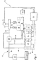
- An internal combustion engine carries in FIG. 1 the reference numeral 10 as a whole. It comprises a fuel system 12.
- the fuel system 12 in turn comprises a fuel tank 14 from which an electric fuel pump 16 delivers fuel.
- the electric fuel pump 16 conveys the fuel via a low-pressure fuel line 18 to a high-pressure fuel pump 20.
- the electric fuel pump 16 thus forms a "prefeed pump" for the high-pressure fuel pump 20.
- the high-pressure fuel pump 20 compresses the fuel to a very high pressure and delivers it via a high-pressure fuel line 22 to a fuel rail 24. In this, the fuel can be stored under very high pressure.
- a plurality of injectors 26 are connected, which the fuel directly in each associated Inject combustion chambers 28.
- a crankshaft 30 is set in motion, which, usually with the interposition of a camshaft, via a mechanical connection 32, the high-pressure fuel pump 20 drives.
- the internal combustion engine 10 also includes an electric starter motor 34, the output shaft 35 is connected to a switchable clutch 36 and an intermediate gear 37.
- the shiftable clutch 36 and the transmission 37 are connected via a mechanical connection 38 to the crankshaft 30.
- the output shaft 35 of the electric starter motor 34 is connected via a mechanical connection 40 but also with an additional high-pressure fuel pump 42.
- the electric starter motor 34, the shiftable clutch 36 and the transmission 37 and the additional high-pressure fuel pump 42 are combined in a rigid assembly 44.
- the additional high-pressure fuel pump 42 is also arranged fluidically parallel to the mechanically driven high-pressure fuel pump 20. This means that it is connected on the inlet side via a channel 46 to the low pressure fuel line 18, whereas it is connected on the outlet side via a high pressure passage 48 to the high pressure fuel line 22. It is understood that the independent operation of the mechanically driven high-pressure fuel pump 20 or the additional high-pressure fuel pump 42 is ensured by a suitable arrangement of non-return valves.
- the operation of the internal combustion engine 10 is controlled by a control and regulating device 50.
- the Control and regulating unit 50 is connected on the input side to an ignition switch 52. It also contains signals from a pressure sensor 54 which detects the pressure in the fuel rail 24. On the output side, the control and regulating unit 50 is connected, on the one hand, to the shiftable clutch 36 and, on the other hand, to the electric starter motor 34.
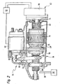
- the assembly 44 which includes the electric starter motor 34, the shiftable clutch 36, the transmission 37, and the additional high pressure fuel pump 42 is shown in detail in Figure 2: the electric starter motor 34, the shiftable clutch 36, and the transmission 37th are housed in a common, multi-part housing 56.
- the transmission 37 is a planetary gear.
- the switchable coupling 36 comprises a switchable. Electromagnet 58, which is also referred to as "Einspurmagnet". A switching element 60 of the electromagnet 58 is connected to a lever 62. The lever 62 is pivotally mounted at 64. The other end of the lever 62 is connected to a shift sleeve 66, with which a "Einpurritzel” 68, which is arranged on the output side of the transmission 37, can be brought into engagement with the mechanical connection 38.
- the additional high-pressure fuel pump 42 is arranged in Figure 2 on the right side. It also comprises a housing 70, which is flanged in a manner not shown here firmly to the housing 56 of the electric starter motor 34, the shiftable clutch 36 and the transmission 37.
- the additional high-pressure fuel pump 42 is a simple and comparatively large tolerances Hergescellte single-cylinder radial piston pump.
- a drive shaft 71 of the additional high-pressure fuel pump 42 is mounted in the housing 70 and rigidly and non-detachably coupled via the mechanical connection 40 to the output shaft of the electric starter motor 34.
- the starting process of the internal combustion engine 10 will now be explained with reference to the flowchart shown in Figure 3.
- the corresponding method is stored as a computer program on a memory of the control and regulating device 50.
- a check is made in block 74 to see if there is a start request.
- the signals of the ignition switch 52 are evaluated. If it is determined in block 74 that the user wants to start the engine 10, it is checked in block 76 whether the pressure pr of the fuel in the fuel rail 24 is below a threshold value G.
- the pressure pr is detected by the sensor 54, which forwards a corresponding signal to the control and regulating device 50.
- the limit value G is selected such that, when the fuel pressure pr in the fuel rail is at least approximately equal to the limit value G, good atomization of the fuel by the injectors 26 can be assumed.
- the fuel pressure pr would normally have dropped to a value below the limit value G. This is due to the fact that the pressure in the fuel rail 24 is deliberately lowered when the internal combustion engine 10 is switched off for safety reasons. In this way, among other things to avoid that in a leaking injector 26 when the engine 10 is turned off fuel in a combustion chamber 28 passes.
- the electromagnet 58 is activated in block 78 in such a way that the single-pinion 68 is decoupled from the crankshaft 30. Further, in block 80, the electric starter motor 34 is driven to operate at full power, i. H. with high torque and high speed, works. At the same time, a counter t is set in motion. It goes without saying that the electric prefeed pump 16 is normally put into operation when a start request is detected. At the inlet of the additional fuel pump 42 is thus provided by the prefeed pump 16 form, generally about 6 bar on.
- the current state of the counter t is compared with a limit value T.
- the electric starter motor 34 is activated in block 84 in such a way that it only operates with comparatively low power, ie low torque.
- the solenoid 58 is driven so that the Einspurritzel 68 establishes a connection of the electric starter motor 34 with the crankshaft 30.
- the block 88 with engaged Einpurritzel 68 of the electric starter motor 34 is again driven so that it works with high power, ie with high torque.
- This starting sequence includes, for example, turning on the ignition, driving the injectors 26 to inject the amount of fuel required to start under the given conditions into the combustion chambers 28, and disengaging the single sprocket 68 and shutting off the electric starter motor 34 as soon as it is started Internal combustion engine 10 has started.
- the method illustrated in FIG. 3 ends in block 90.
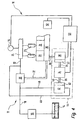
- FIG. 4 shows a second exemplary embodiment of an internal combustion engine 10.
- elements and areas which have equivalent functions to elements and areas of the embodiment shown in Figures 1 to 3, the same reference numerals. They are not explained again in detail.
- the starting process of the internal combustion engine 10 it is also possible for the starting process of the internal combustion engine 10 to take place without actuation of the electric starter motor 34.
- the commissioning of the internal combustion engine 10 takes place in this case exclusively by the Injection of fuel through an injector 26 in a combustion chamber 28 associated with it, and by the subsequent ignition of the fuel LufL Gernisch in this combustion chamber 23.
- a prerequisite is a corresponding positioning of the piston in the cylinder in which the initial injection of fuel takes place.
- the end of the actual operation of the additional high-pressure fuel pump may be determined instead of by a counter by monitoring the pressure pr in the fuel rail 24.
- the starter would be driven again with low torque when the pressure pr in the fuel rail exceeds a threshold.
- the pressure build-up in the fuel collecting line 24 can also be initiated, for example, by detecting an actuation signal of a wireless locking system of the vehicle, in which the internal combustion engine is installed, or an actuation signal, for example, of a driver's door of this motor vehicle.
Landscapes
- Engineering & Computer Science (AREA)
- Chemical & Material Sciences (AREA)
- Combustion & Propulsion (AREA)
- Mechanical Engineering (AREA)
- General Engineering & Computer Science (AREA)
- Fuel-Injection Apparatus (AREA)
- Electrical Control Of Air Or Fuel Supplied To Internal-Combustion Engine (AREA)
Description
- Die Erfindung betrifft zunächst eine Brennkraftmaschine mit einem elektrischen Startermotor zum Starten der Brennkraftmaschine und mit einem Kraftstoffsystem mit einer mechanisch angetriebenen Hochdruck-Kraftstoffpumpe.
- Eine derartige Brennkraftmaschine ist vom Markt her bekannt. Der elektrische Startermotor ("Anlasser") wird üblicherweise bei Betätigung eines Zündschalters über ein schaltbares Ritzel an die Kurbelwelle der Brennkraftmaschine angekoppelt. Nach erfolgtem Startvorgang wird der elektrische Startermotor wieder von der Kurbelwelle der Brennkraftmaschine entkoppelt und abgeschaltet.
- Bei Brennkraftmaschinen mit Kraftstoff-Direkteinspritzung ist ferner eine von der Nockenwelle der Brennkraftmaschine mechanisch angetriebene Hochdruck-Kraftstoffpumpe vorhanden. Diese fördert den Kraftstoff in eine Kraftstoff-Sammelleitung ("Rail"), in der der Kraftstoff unter hohem Druck gespeichert ist. An die Kraftstoff-Sammelleitung sind mehrere Injektoren angeschlossen, die den Kraftstoff direkt in ihnen jeweils zugeordnete Brennräume einspritzen.
- Um eine sichere und emissions- sowie verbrauchsoptimale Zündung des Kraftstoffes im Brennraum zu erzielen, ist eine gute Vernebelung des Kraftstoffes durch den Injektor erforderlich. Diese setzt wiederum einen relativ hohen Druck des Kraftstoffes in der Kraftstoff-Sammelleitung voraus. Aus Sicherheitsgründen wird der Druck des Kraftstoffes in der Kraftstoff-Sammelleitung jedoch bei abgestellter Brennkraftmaschine abgesenkt. Da dieser hohe Druck von der mechanisch angetriebenen Hochdruck-Kraftstoffpumpe erst nach einigen Kurbelwellenumdrehungen wieder hergestellt werden kann, liegt zumindest bei den ersten Einspritzungen des Kraftstoffs in die Brennräume der für eine gute Zerstäubung an sich geforderte hohe Kraftstoffdruck nach dem Abstellen der Brennkraftmaschine nicht vor.
- Zur Lösung dieses Problems wird in der DE 198 18 421 A1 vorgeschlagen, eine elektrisch angetriebene Vorförderpumpe, welche den Kraftstoff von einem Kraftstoffbehälter zu der Hochdruck-Kraftstoffpumpe fördert, während der Startphase mit erhöhter Förderleistung zu betreiben. Dabei ist jedoch problematisch, dass übliche Vorförderpumpen auch bei erhöhter Förderleistung noch nicht jenen Drück bereitstellen können, der für eine optimale Zerstäubung des Kraftstoffs in den Brennräumen erforderlich ist.
- Die DE 199 39 051 A1 schlägt zur Lösung des oben genannten Problems vor, eine zusätzliche, elektrisch angetriebene Hochdruck-Kraftstoffpumpe vorzusehen, welche fluidisch parallel zu der mechanisch angetriebenen Hochdruck-Kraftstoffpumpe geschaltet ist. Die zusätzliche elektrisch angetriebene Hochdruck-Kraftstoffpumpe wird vor oder während der Motorstartphase in Betrieb genommen. Der Nachteil dieses Konzepts liegt jedoch in der Baugröße der zusätzlichen elektrischen Kraftstoffpumpe und in den hohen Zusatzkosten.
- In der DE 33 04 605 A1 und der US 2001/0011537 werden Kraftstoffsysteme mit einer Kraftstoffpumpe beschreiben, die von einem Startermotor der Brennkraftmaschine angetrieben werden kann.
- Die vorliegende Erfindung hat die Aufgabe, eine Brennkraftmaschine der eingangs genannten Art so weiterzubilden, dass sie möglichst einfach und preiswert baut.
- Diese Aufgabe wird bei einer Brennkraftmaschine der eingangs genannten Art dadurch gelöst, dass eine zusätzliche Hochdruck-Kraftstoffpumpe vorhanden ist, welche wenigstens zeitweise direkt von dem elektrischen Startermotor angetrieben wird, und dass die zusätzliche Hochdruck-Kraftstoffpumpe und der elektrische Startermotor eine Baueinheit bilden.
- Bei der erfindungsgemäßen Brennkraftmaschine ist gegenüber einer herkömmlichen Brennkraftmaschine als zusätzliches Teil nur eine kleine Zusatz-Kraftstoffpumpe vorhanden, nicht jedoch ein zusätzlicher Antrieb. Angetrieben wird die zusätzliche Hochdruck-Kraftstoffpumpe von dem ohnehin bei allen üblichen Brennkraftmaschinen vorhandenen elektrischen Startermotor. Die zusätzlich vorzusehenden Kosten sind daher vergleichsweise gering, und der zusätzlich notwendige Bauraum ist klein, da bei dem erfindungsgemäßen Konzept für die Pumpe kein spezieller Antrieb benötigt wird. Darüber hinaus kann bei der erfindungsgemäßen Brennkraftmaschine auch deshalb eine kleine und preiswerte zusätzliche Hochdruck-Kraftstoffpumpe verwendet werden, da sichergestellt ist, dass diese insgesamt nur vergleichsweise kurz in Betrieb ist, denn ihre Betriebsweise entspricht der des Anlassers - sie arbeitet nämlich immer nur sehr kurz. Dadurch, dass der elektrische Startermotor und die zusätzliche Hochdruck-Kraftstoffpumpe eine Baueinheit bilden, wird die Handhabung beim Zusammenbau der Brennkraftmaschine nochmals vereinfacht.
- Vorteilhafte Weiterbildungen der Erfindung sind in Unteransprüchen angegeben.
- In einer ersten Weiterbildung der erfindungsgemäßen Brennkraftmaschine wird vorgeschlagen, dass eine Antriebswelle der zusätzlichen Hochdruck-Kraftstoffpumpe mit einer Abtriebswelle des elektrischen Startermotors starr und im Betrieb unlösbar gekoppelt ist. Diese Ausgestaltung der erfindungsgemäßen Brennkraftmaschine ist besonders einfach und preiswert.
- Möglich ist aber auch, dass eine Antriebswelle der zusätzlichen Hochdruck-Kraftstoffpumpe mit einer Abtriebswelle des elektrischen Startermotors über eine im Betrieb schaltbare Kupplung lösbar gekoppelt ist. Somit kann die zusätzliche Hochdruck-Kraftstoffpumpe während des eigentlichen Startvorgangs von dem elektrischen Startermotor abgekoppelt werden, so dass die gesamte Leistung des elektrischen Startermotors für das Inbewegungsetzen der Kurbelwelle der Brennkraftmaschine zur verfügung steht, und wodurch die Gesamt-Betriebsdauer der zusätzlichen Hochdruck-Kraftstoffpumpe nochmals reduziert wird.
- Besonders vorteilhaft ist es, wenn die zusätzliche Hochdruck-Kraftstoffpumpe am elektrischen Startermotor gehaltert ist, denn dann kann auf eine separate Lagerung der zusätzlichen Hochdruck-Kraftstoffpumpe verzichtet werden. Auch der Zusammenbau der Brennkraftmaschine wird hierdurch vereinfacht, da weniger separate Teile handzuhaben sind.
- Besonders vorteilhaft ist jene Ausgestaltung der erfindungsgemäßen Brennkraftmaschine, bei welcher der elektrische Startermotor ein hochdrehender Elektromotor, und bei welcher die zusätzliche Hochdruck-Kraftstoffpumpe eine Zahnrad- oder eine G-Rotor-Pumpe oder eine Kolbenpumpe mit großer Toleranz umfasst. Als hochdrehender Elektromotor wird ein Elektromotor verstanden, dessen Abtriebswelle sich mit mindestens 10.000 1/min, gegebenenfalls mit bis zu 15.000 1/min dreht.
- Derartige Hochdruck-Kraftstoffpumpen bauen einfach, klein und sind preiswert. Ihr vergleichsweise geringer Wirkungsgrad wird durch die hohen Drehzahlen des elektrischen Startermotors kompensiert.
- Die vorliegende Erfindung betrifft auch ein Verfahren zum Betreiben einer Brennkraftmaschine, bei dem eine Kurbelwelle der Brennkraftmaschine von einem elektrischen Startermotor in Drehung versetzt und auf diese Weise die Brennkraftmaschine gestartet werden kann, und bei dem der Kraftstoff von einer mechanisch von der Brennkraftmaschine Hochdruck-Kraftstoffpumpe gefördert wird.
- Auch ein solches Verfahren ist vom Markt her bekannt. Bezüglich der Nachteile des bekannten Verfahrens wird auf die oben im Zusammenhang mit der bekannten Brennkraftmaschine angeführten Nachteile verwiesen.
- Um das Startverhalten der Brennkraftmaschine insbesondere im Hinblick auf die Emissionen und den Kraftstoffverbrauch zu verbessern, ohne erhebliche Zusatzkosten zu verursachen, wird vorgeschlagen, dass der Kraftstoff wenigstens zeitweise von einer zusätzlichen Hochdruck-Kraftstoffpumpe gefördert wird, welche vom elektrischen Startermotor direkt angetrieben wird und mit dem elektrischen Startermotor eine Baueinheit bildet.
- Auch bezüglich der Vorteile des erfindungsgemäßen Verfahrens wird auf die oben angegebenen Vorteile der erfindungsgemäßen Brennkraftmaschine verwiesen. Besonders vorteilhaft wirkt sich das erfindungsgemäße Verfahren dann aus, wenn die Brennkraftmaschine im Normalfall durch Einspritzen von Kraftstoff in einen Brennraum und Zünden des eingespritzten Kraftstoffes, ohne Drehung der Kurbelwelle mittels des elektrischen Startermotors, gestartet wird. Vor allem bei diesem, auch als "Direktstart" bekannten Verfahren führt der hohe Kraftstoffdruck, der beim Starten durch den Betrieb der zusätzlichen Hochdruck-Kraftstoffpumpe bereitgestellt werden kann, zu einer guten Zerstäubung, was wiederum eine sichere Zündung des eingespritzten Kraftstoffes gewährleistet. Gleichzeitig wird das bisweilen unangenehme Anlassergeräusch vermieden, welches auftritt, wenn der Anlasser die Kurbelwelle in Drehung versetzt.
- In einer vorteilhaften Weiterbildung des erfindungsgemäßen Verfahrens wird vorgeschlagen, dass die zusätzliche Hochdruck-Kraftstoffpumpe nur während eines Zeitraums von dem elektrischen Startermotor angetrieben wird, welcher vor dem Starten der Brennkraftmaschine liegt. Hierdurch wird die Gesamt-Betriebszeit der zusätzlichen Hochdruck-Kraftstoffpumpe verkürzt, so dass eine einfache und preiswerte Hochdruck-Kraftstoffpumpe verwendet werden kann. Darüber hinaus steht während des eigentlichen Startvorgangs der Brennkraftmaschine die gesamte Leistung des elektrischen Startermotors zum Inbewegungsetzen der Kurbelwelle der Brennkraftmaschine zur Verfügung.
- Ferner wird vorgeschlagen, dass der Startermotor zunächst von der Kurbelwelle getrennt ist und bei angekoppelter zusätzlicher Hochdruck-Kraftstoffpumpe betrieben wird, dass dann das Drehmoment des elektrischen Startermotors reduziert wird, und dass dann die Kurbelwelle vom elektrischen Startermotor in Drehung versetzt wird. Dies ermöglicht ein geräuscharmes und die Kupplung schonendes Ankuppeln des elektrischen Startermotors an die Kurbelwelle der Brennkraftmaschine, ohne dass auf die volle Leistung des elektrischen Startermotors zum Antrieb der zusätzlichen Hochdruck-Kraftstoffpumpe verzichtet werden muss.
- Möglich ist auch, dass die zusätzliche Hochdruck-Kraftstoffpumpe nur dann von dem elektrischen Startermotor angetrieben wird, wenn ein Kraftstoffdruck unterhalb eines Grenzwerts liegt. So ist es beispielsweise möglich, dass der Druck in einer Kraftstoff-Sammelleitung ("Rail") von einem Sensor erfasst wird. Ist der Druck in der Kraftstoff-Sammelleitung noch ausreichend hoch, beispielsweise wenn die Brennkraftmaschine nur für sehr kurze Zeit abgestellt worden war, wird auf den Betrieb der zusätzlichen Hochdruck-Kraftstoffpumpe verzichtet. Auch hierdurch wird die Gesamt-Betriebsdauer der zusätzlichen Hochdruck-Kraftstoffpumpe reduziert, so dass eine kleine und preiswerte Hochdruck-Kraftstoffpumpe verwendet werden kann.
- Nachfolgend wird ein besonders bevorzugtes Ausführungsbeispiel der vorliegenden Erfindung unter Bezugnahme auf die beiliegende Zeichnung im Detail erläutert. In der Zeichnung zeigen:
- Figur 1
- eine schematische Darstellung eines ersten Ausführungsbeispiels einer Brennkraftmaschine mit einer zusätzlichen Hochdruck-Kraftstoffpumpe;
- Figur 2
- einen teilweiser. Schnitt durch die zusätzliche Hochdruck-Kraftstoffpumpe von Figur 1;
- Figur 3
- ein Ablaufdiagramm zum Betrieb der zusätzlichen Hochdruck-Kraftstoffpumpe von Figur 1; und
- Figur 4
- eine Darstellung ähnlich Figur 1 eines zweiten Ausführungsbeispiels einer Brennkraftmaschine.
- Eine Brennkraftmaschine trägt in Figur 1 insgesamt das Bezugszeichen 10. Sie umfasst ein Kraftstoffsystem 12.
- Das Kraftstoffsystem 12 umfasst wiederum einen Kraftstoffbehälter 14, aus dem eine elektrische Kraftstoffpumpe 16 Kraftstoff fördert. Die elektrische Kraftstoffpumpe 16 fördert den Kraftstoff über eine Niederdruck-Kraftstoffleitung 18 zu einer Hochdruck-Kraftstoffpumpe 20. Die elektrische Kraftstoffpumpe 16 bildet also eine "Vorförderpumpe" für die Hochdrdck-Kraftstoffpumpe 20.
- Die Hochdruck-Kraftstoffpumpe 20 verdichtet den Kraftstoff auf einen sehr hohen Druck und fördert ihn über eine Hochdruck-Kraftstoffleitung 22 zu einer Kraftstoff-Sammelleitung 24. In dieser kann der Kraftstoff unter sehr hohem Druck gespeichert werden. An die Kraftstoff-Sammelleitung 24 sind mehrere Injektoren 26 angeschlossen, die den Kraftstoff direkt in ihnen jeweils zugeordnete Brennräume 28 einspritzen. Durch eine Verbrennung des eingespritzten Kraftstoffs in den Brennräumen 28 wird eine Kurbelwelle 30 in Bewegung gesetzt, welche, üblicherweise unter Zwischenschaltung einer Nockenwelle, über eine mechanische Verbindung 32 die Hochdruck-Kraftstoffpumpe 20 antreibt.
- Die Brennkraftmaschine 10 umfasst auch einen elektrischen Startermotor 34, dessen Abtriebswelle 35 mit einer schaltbaren Kupplung 36 und einem Zwischengetriebe 37 verbunden ist. Die schaltbare Kupplung 36 und das Getriebe 37 sind über eine mechanische Verbindung 38 mit der Kurbelwelle 30 verbunden. Die Abtriebswelle 35 des elektrischen Startermotors 34 ist über eine mechanische Verbindung 40 aber auch mit einer zusätzlichen Hochdruck-Kraftstoffpumpe 42 verbunden. Der elektrische Startermotor 34, die schaltbare Kupplung 36 und das Getriebe 37 und die zusätzliche Hochdruck-Kraftstoffpumpe 42 sind in einer starren Baueinheit 44 zusammengefasst.
- Die zusätzliche Hochdruck-Kraftstoffpumpe 42 ist ferner fluidisch parallel zu der mechanisch angetriebenen Hochdruck-Kraftstöffpumpe 20 angeordnet. Dies bedeutet, dass sie einlassseitig über einen Kanal 46 an die Niederdruck-Kraftstoffleitung 18 angeschlossen ist, wohingegen sie auslassseitig über einen Hochdruckkanal 48 an die Hochdruck-Kraftstoffleitung 22 angeschlossen ist. Es versteht sich, dass durch eine entsprechende geeignete Anordnung von Rückschlagventilen der unabhängige Betrieb der mechanisch angetriebenen Hochdruck-Kraftstoffpumpe 20 bzw. der zusätzlichen Hochdruck-Kraftstoffpumpe 42 gewährleistet ist.
- Der Betrieb der Brennkraftmaschine.l0 wird von einem Steuer- und Regelgerät 50 gesteuert bzw. geregelt. Das Steuer- und Regelgerät 50 ist eingangsseitig mit einem Zündschalter 52 verbunden. Ferner enthält es Signale von einem Drucksensor 54, welcher den Druck in der Kraftstoff-Sammelleitung 24 erfasst. Ausgangsseitig ist das Steuer-und Regelgerät 50 einerseits mit der schaltbaren Kupplung 36 und andererseits mit dem elektrischen Startermotor 34 verbunden.
- Die Baueinheit 44, welche den elektrischen Startermotor 34, die schaltbare Kupplung 36, das Getriebe 37 , und die zusätzliche Hochdruck-Kraftstoffpumpe 42 umfasst, ist im Detail in Figur 2 dargestellt: Der elektrische Startermotor 34, die schaltbare Kupplung 36, und das Getriebe 37 sind in einem gemeinsamen, mehrteiligen Gehäuse 56 untergebracht. Bei dem Getriebe 37 handelt es sich um ein Planetengetriebe.
- Die schaltbare Kupplung 36 umfasst einen schaltbaren. Elektromagnet 58, welcher auch als "Einspurmagnet" bezeichnet wird. Ein Schaltelement 60 des Elektromagneten 58 ist mit einem Hebel 62 verbunden. Der Hebel 62 ist bei 64 schwenkbar gelagert. Das andere Ende des Hebels 62 ist mit einer Schalthülse 66 verbunden, mit welcher ein "Einspurritzel" 68, welches abtriebsseitig vom Getriebe 37 angeordnet ist, in Eingriff mit der mechanischen Verbindung 38 gebracht werden kann.
- Die zusätzliche Hochdruck-Kraftstoffpumpe 42 ist in Figur 2 auf der rechten Seite angeordnet. Sie umfasst ebenfalls ein Gehäuse 70, welches auf hier nicht näher dargestellte Art und Weise fest an das Gehäuse 56 des elektrischen Startermotors 34, der schaltbarer Kupplung 36 und des Getriebes 37 angeflanscht ist. Bei der zusätzlichen Hochdruck-Kraftstoffpumpe 42 handelt es sich um eine einfache und mit vergleichsweise großen Toleranzen hergescellte Einzylinder-Radialkolbenpumpe. Eine Antriebswelle 71 der zusätzlichen Hochdruck-Kraftstoffpumpe 42 ist in dem Gehäuse 70 gelagert und über die mechanische Verbindung 40 mit der Abtriebswelle des elektrischen Startermotors 34 starr und unlösbar gekoppelt.
- Der Startvorgang der Brennkraftmaschine 10 wird nun unter Bezugnahme auf das in Figur 3 dargestellte Ablaufdiagramm erläutert. Das entsprechende Verfahren ist als Computerprogramm auf einem Speicher des Steuer- und Regelgeräts 50 abgespeichert. Nach einem Startblock 72 wird im Block 74 geprüft, ob eine Anlassaufforderung vorliegt. Hierzu werden die Signale des Zündschalters 52 ausgewertet. Wenn im Block 74 festgestellt wird, dass der Benutzer die Brennkraftmaschine 10 starten will, wird im Block 76 geprüft, ob der Druck pr des Kraftstoffes in der Kraftstoff-Sammelleitung 24 unterhalb eines Grenzwerts G liegt. Der Druck pr wird dabei vom Sensor 54 erfasst, welcher ein entsprechendes Signal an das Steuer- und Regelgerät 50 weiterleitet. Der Grenzwert G ist so gewählt, dass dann, wenn der Kraftstoffdruck pr in der Kraftstoff-Sammelleitung mindestens in etwa gleich dem Grenzwert G ist, von einer guten Zerstäubung des Kraftstoffs durch die Injektoren 26 ausgegangen werden kann.
- Ist die Brennkraftmaschine 10 für einen längeren Zeitraum abgestellt gewesen, dürfte üblicherweise der Kraftstoffdruck pr auf einen Wert unterhalb der Grenzwerts G abgesunken sein. Dies hängt damit zusammen, dass der Druck in der Kraftstoff-Sammelleitung 24 bei abgeschalteter Brennkraftmaschine 10 aus Sicherheitsgründen bewusst abgesenkt wird. Auf diese Weise soll unter anderem vermieden werden, dass bei einem undichten Injektor 26 bei abgestellter Brennkraftmaschine 10 Kraftstoff in einen Brennraum 28 gelangt. Das Absinken des Kraftstoffdrucks pr in der Kraftstoff-Sammelleitung 24 erfolgt jedoch üblicherweise vergleichsweise langsam, so dass nach einer nur kurzen Abstellphase der Brennkraftmaschine 10 möglicherweise noch ein ausreichender und oberhalb des Grenzwerts G liegender Kraftstoffdruck pr in der Kraftstoff-Sammelleitung 24 herrscht.
- Wird im Block 76 jedoch festgestellt, dass der Kraftstoffdruck pr in der Kraftstoff-Sammelleitung 24 unterhalb des Grenzwerts G liegt, wird im Block 78 der Elektromagnet 58 so angesteuert, dass das Einspurritzel 68 von der Kurbelwelle 30 entkoppelt ist. Weiter wird im Block 80 der elektrische Startermotor 34 so angesteuert, dass er mit voller Leistung, d. h. mit hohem Drehmoment und hoher Drehzahl, arbeitet. Gleichzeitig wird ein Zähler t in Gang gesetzt. Dabei versteht es sich, dass im Normalfall bei einer festgestellten Anlassaufforderung auch die elektrische Vorförderpumpe 16 in Betrieb genommen wird. Am Einlass der zusätzlichen Kraftstoffpumpe 42 liegt also der von der Vorförderpumpe 16 bereitgestellte Vordruck, im Allgemeinen ca. 6 bar, an.
- Im Block 82 wird der aktuelle Stand des Zählers t mit einem Grenzwert T verglichen. Sobald der Grenzwert T erreicht ist, wird im Block 84 der elektrische Startermotor 34 so angesteuert, dass er nur noch mit vergleichsweise geringer Leistung, also geringem Drehmoment, arbeitet. Dann wird im Block 86 der Elektromagnet 58 so angesteuert, dass das Einspurritzel 68 eine Verbindung des elektrischen Startermotors 34 mit der Kurbelwelle 30 herstellt. Weiter wird im Block 88 mit eingekuppeltem Einspurritzel 68 der elektrische Startermotor 34 wieder so angesteuert, dass er mit hoher Leistung, also mit hohem Drehmoment, arbeitet.
- Ferner wird die übliche Anlasssequenz der Brennkraftmaschine 10 in Gang gesetzt. Diese Anlasssequenz umfasst beispielsweise das Einschalten der Zündung, die Ansteuerung der Injektoren 26, so class diese die für den Start unter den gegebenen Bedingungen erforderliche Kraftstoffmenge in die Brennräume 28 einspritzen, und das Auskuppeln des Einspurritzels 68 und das Abschalten des elektrischen Startermotors 34, sobald die Brennkraftmaschine 10 angesprungen ist. Das in Figur 3 dargestellte Verfahren endet im Block 90.
- In Figur 4 ist ein zweites Ausführungsbeispiel einer Brennkraftmaschine 10 dargestellt. Dabei tragen solche Elemente und Bereiche, welche äquivalente Funktionen zu Elementen und Bereichen des in den Figuren 1 bis 3 dargestellten Ausführungsbeispiels aufweisen, die gleichen Bezugszeichen. Sie sind nicht nochmals im Detail erläutert.
- Der wesentliche Unterschied der in Figur 4 dargestellten Brennkraftmaschine 10 zu jener der Figuren 1 bis 3 besteht darin, dass zwischen der zusätzlichen Hochdruck-Kraftstoffpumpe 42 und dem elektrischen Startermotor 34 eine schaltbare Kupplung 92 vorgesehen ist. Ober diese kann die zusätzliche Hochdruck-Kraftstoffpumpe 42 vom elektrischen Startermotor 34 entkoppelt werden. In der Praxis bedeutet dies, dass die zusätzliche Hochdruck-Kraftstoffpumpe 42 nur während eines Zeitraums von dem elektrischen Startermotor 34 angetrieben wird, welcher vor dem Starten, d. h. dem Inbewegungsetzen der Kurbelwelle 30, der Brennkraftmaschine 10 liegt.
- Alternativ zu dem in Figur 3 dargestellten Verfahren ist es auch möglich, dass der Anlassvorgang der Brennkraftmaschine 10 ohne Betätigung des elektrischen Startermotors 34 erfolgt. Die Inbetriebnahme der Brennkraftmaschine 10 erfolgt in diesem Fall ausschließlich durch die Einspritzung von Kraftstoff durch einen Injektor 26 in einen ihm zugeordneten Brennraum 28, und durch die anschließende Entzündung des Kraftstoff-LufL-Gernisches in diesem Brennraum 23. Voraussetzung ist allerdings eine entsprechende Positionierung des Kolbens in dem Zylinder, in dem die Ersteinspritzung von Kraftstoff erfolgt.
- Ferner kann das Ende des eigentlichen Betriebs der zusätzlichen Hochdruck-Kraftstoffpumpe anstelle durch einen Zähler durch eine Überwachung des Drucks pr in der Kraftstoff-Sammelleitung 24 bestimmt werden. In diesem Falle würde der Anlasser wieder mit geringem Drehmoment angetrieben werden, wenn der Druck pr in der Kraftstoff-Sammelleitung einen Grenzwert überschreitet.
- Weiter sei darauf hingewiesen, dass der Druckaufbau in der Kraftstoff-Sammelleitung 24 beispielsweise auch dadurch initiiert werden kann, dass ein Betätigungssignal einer drahtlosen Schließanlage des Fahrzeugs, in welches die Brennkraftmaschine eingebaut ist, oder ein Betätigungssignal beispielsweise einer Fahrertüre dieses Kraftfahrzeugs erfasst wird.
Claims (9)
- Brennkraftmaschine (10) mit einem elektrischen Startermotor (34) zum Starten der Brennkraftmaschine (10) und mit einem Kraftstoffsystem (12) mit einer mechanisch angetriebenen Hochdruck-Kraftstoffpumpe (20), dadurch gekennzeichnet, dass eine zusätzliche Hochdruck-Kraftstoffpumpe (42) vorhanden ist, welche wenigstens zeitweise direkt von dem elektrischen Startermotor (34) angetrieben wird, und dass die zusätzliche Hochdruck-Kraftstoffpumpe (42) und der elektrische Startermotor (34) Teil einer gemeinsamen Baueinheit (44) sind.
- Brennkraftmaschine (10) nach Anspruch 1, dadurch gekennzeichnet, dass eine Antriebswelle (71) der zusätzlichen Hochdruck-Kraftstoffpumpe (42) mit einer Abtriebswelle (35) des elektrischen Startermotors (34) starr und im Betrieb unlösbar gekoppelt ist.
- Brennkraftmaschine (10) nach Anspruch 1, dadurch gekennzeichnet, dass eine Antriebswelle (71) der zusätzlichen Hochdruck-Kraftstoffpumpe (42) mit einer Abtriebswelle (35) des elektrischen Startermotors (34) über eine im Betrieb schaltbare Kupplung (92) lösbar gekoppelt ist.
- Brennkraftmaschine (10) nach einem der vorhergehenden Ansprüche, dadurch gekennzeichnet, dass die zusätzliche Hochdruck-Kraftstoffpumpe (42) und der elektrische Startermotor (34) gemeinsam gehaltert sind.
- Brennkraftmaschine (10) nach einem der vorhergehenden Ansprüche, dadurch gekennzeichnet, dass der elektrische Startermotor einen hochdrehenden Elektromotor (34) umfasst, und dass die zusätzliche Hochdruck-Kraftstoffpumpe eine Zahnrad- oder eine G-Rotor-Pumpe oder eine Kolbenpumpe (42) mit großer Toleranz umfasst.
- Verfahren zum Betreiben einer Brennkraftmaschine (10), bei dem eine Kurbelwelle (30) der Brennkraftmaschine (10) von einem elektrischen Startermotor (34) in Drehung versetzt und auf diese Weise die Brennkraftmaschine (10) gestartet werden kann, und bei dem der Kraftstoff von einer mechanisch von der Brennkraftmaschine (10) angetriebenen Hochdruck-Kraftstoffpumpe (20) gefördert wird, dadurch gekennzeichnet, dass der Kraftstoff wenigstens zeitweise von einer zusätzlichen Hochdruck-Kraftstoffpumpe (42) gefördert wird, welche vom elektrischen Startermotor (34) direkt angetrieben wird und mit dem elektrischen Startermotor eine Baueinheit bildet, wobei die Brennkraftmaschine (10) im Normalfall durch Einspritzen von Kraftstoff in einen Brennraum (28) und Zünden des eingespritzten Kraftstoffes, ohne Drehung der Kurbelwelle (30) mittels des elektrischen Startermotors (34), gestartet wird.
- Verfahren nach Anspruch 6, dadurch gekennzeichnet, dass die zusätzliche Hochdruck-Kraftstoffpumpe (42) nur während eines Zeitraums von dem elektrischen Startermotor (34) angetrieben wird, welcher vor dem Starten der Brennkraftmaschine (10) liegt.
- Verfahren nach einem der Ansprüche 6 oder 7, dadurch gekennzeichnet, dass der Startermotor (34) zunächst von der Kurbelwelle (30) getrennt ist und bei angekoppelter zusätzlicher Hochdruck-Kraftstoffpumpe (34) betrieben wird, dass dann das Drehmoment des elektrischen Startermotors (34) reduziert wird, und dass dann die Kurbelwelle (30) vom elektrischen Startermotor (34) in Drehung versetzt wird.
- Verfahren nach einem der Ansprüche 6 bis 8, dadurch gekennzeichnet, dass die zusätzliche Hochdruck-Kraftstoffpumpe (42) nur dann von dem elektrischen Startermotor (34) angetrieben wird, wenn ein Kraftstoffdruck (pr) unterhalb eines Grenzwerts (G) liegt.
Applications Claiming Priority (2)
| Application Number | Priority Date | Filing Date | Title |
|---|---|---|---|
| DE10254735A DE10254735A1 (de) | 2002-11-23 | 2002-11-23 | Brennkraftmaschine, sowie Verfahren zum Betreiben einer Brennkraftmaschine |
| DE10254735 | 2002-11-23 |
Publications (2)
| Publication Number | Publication Date |
|---|---|
| EP1422416A1 EP1422416A1 (de) | 2004-05-26 |
| EP1422416B1 true EP1422416B1 (de) | 2006-03-08 |
Family
ID=32185923
Family Applications (1)
| Application Number | Title | Priority Date | Filing Date |
|---|---|---|---|
| EP03012486A Expired - Lifetime EP1422416B1 (de) | 2002-11-23 | 2003-06-02 | Brennkraftmaschine, sowie Verfahren zum Betreiben einer Brennkraftmaschine |
Country Status (2)
| Country | Link |
|---|---|
| EP (1) | EP1422416B1 (de) |
| DE (2) | DE10254735A1 (de) |
Families Citing this family (9)
| Publication number | Priority date | Publication date | Assignee | Title |
|---|---|---|---|---|
| FR2888891B1 (fr) * | 2005-07-19 | 2010-09-17 | Valeo Equip Electr Moteur | Dispositif de demarrage d'un moteur a combustion interne, en particulier d'un moteur diesel |
| WO2008034958A1 (fr) * | 2006-09-22 | 2008-03-27 | Valeo Equipements Electriques Moteur | Dispositif de demarrage d'un moteur a combustion interne, en particulier d'un moteur diesel |
| US8001942B2 (en) * | 2007-10-31 | 2011-08-23 | GM Global Technology Operations LLC | High pressure piston pump actuating system using automotive starter system |
| DE102008041067A1 (de) * | 2008-08-07 | 2010-02-11 | Robert Bosch Gmbh | Druckpumpenvorrichtung für ein Hybridfahrzeug |
| DE102008043595A1 (de) * | 2008-11-10 | 2010-05-27 | Robert Bosch Gmbh | Starteranordnung mit Nebenaggregateantrieb |
| DE102010042600A1 (de) * | 2010-10-19 | 2012-04-19 | Robert Bosch Gmbh | Verfahren zum Betreiben eines Kraftfahrzeugs |
| DE102011087752A1 (de) * | 2011-12-05 | 2013-06-06 | Robert Bosch Gmbh | Kraftstofffördereinrichtung |
| DE102012218525B4 (de) * | 2012-10-11 | 2015-06-03 | Continental Automotive Gmbh | Verfahren und Vorrichtung zum Betreiben einer Brennkraftmaschine |
| DE102013210178A1 (de) * | 2013-05-31 | 2014-12-04 | Robert Bosch Gmbh | Verfahren zum Ansteuern einer Nockenwelle |
Family Cites Families (7)
| Publication number | Priority date | Publication date | Assignee | Title |
|---|---|---|---|---|
| AT380540B (de) * | 1982-02-12 | 1986-06-10 | Steyr Daimler Puch Ag | Kraftstoffeinspritzanlage fuer eine elektrische, ein startschloss umfassende anlasseinrichtung aufweisende kraftfahrzeug-dieselmotoren |
| GB8523442D0 (en) * | 1985-09-23 | 1985-10-30 | Hobourn Eaton Ltd | Drive arrangements |
| DE19539885A1 (de) * | 1995-05-26 | 1996-11-28 | Bosch Gmbh Robert | Kraftstoffversorgungsanlage und Verfahren zum Betreiben einer Brennkraftmaschine |
| DE19818421B4 (de) * | 1998-04-24 | 2017-04-06 | Robert Bosch Gmbh | Kraftstoffversorgungsanlage einer Brennkraftmaschine |
| DE19939051A1 (de) * | 1999-08-18 | 2001-02-22 | Volkswagen Ag | Vorrichtung und Verfahren zur Erzeugung eines Kraftstoffhochdrucks |
| DE10003736A1 (de) * | 2000-01-28 | 2001-08-02 | Bosch Gmbh Robert | Betriebseinrichtung für eine Brennkraftmaschine eines Kraftfahrzeuges mit einem Starter |
| DE10127516A1 (de) * | 2001-06-06 | 2002-12-12 | Bosch Gmbh Robert | Verfahren, Computerprogramm und Steuer- und/oder Regelgerät zum Betreiben einer Brennkraftmaschine sowie Kraftstoffsystem für eine Brennkraftmaschine |
-
2002
- 2002-11-23 DE DE10254735A patent/DE10254735A1/de not_active Withdrawn
-
2003
- 2003-06-02 DE DE50302565T patent/DE50302565D1/de not_active Expired - Lifetime
- 2003-06-02 EP EP03012486A patent/EP1422416B1/de not_active Expired - Lifetime
Also Published As
| Publication number | Publication date |
|---|---|
| DE10254735A1 (de) | 2004-06-03 |
| EP1422416A1 (de) | 2004-05-26 |
| DE50302565D1 (de) | 2006-05-04 |
Similar Documents
| Publication | Publication Date | Title |
|---|---|---|
| EP1296060B1 (de) | Kraftstoffeinspritzeinrichtung für eine Brennkraftmaschine | |
| EP2217795B1 (de) | Kraftstoffeinspritzsystem für eine brennkraftmaschine mit hc-injektor | |
| DE102007000072A1 (de) | Common-Rail-Kraftstoffeinspritzsystem mit Kraftstoffvorbereitungsmechanismus zur Sicherstellung der Stabilität des Betriebs der Piezo-Einspritzvorrichtung | |
| EP2545268B1 (de) | Kraftstoffeinspritzsystem einer brennkraftmaschine | |
| DE102015203348B3 (de) | Verfahren zum Betrieb einer Common-Rail-Einspritzanordnung für eine Brennkraftmaschine mit Stopp-Start-System | |
| DE10048247A1 (de) | Kraftstoffversorgungseinrichtung für eine Brennkraftmaschine | |
| DE10003736A1 (de) | Betriebseinrichtung für eine Brennkraftmaschine eines Kraftfahrzeuges mit einem Starter | |
| EP1422416A1 (de) | Brennkraftmaschine, sowie Verfahren zum Betreiben einer Brennkraftmaschine | |
| DE10127516A1 (de) | Verfahren, Computerprogramm und Steuer- und/oder Regelgerät zum Betreiben einer Brennkraftmaschine sowie Kraftstoffsystem für eine Brennkraftmaschine | |
| EP1149239A1 (de) | Kraftstoffversorgungssystem für eine brennkraftmaschine insbesondere eines kraftfahrzeugs | |
| DE102010028910A1 (de) | Verfahren zum Bereitstellen eines für ein Wiederanlassen einer Common-Rail-Brennkraftmaschine ausreichenden Raildrucks | |
| DE102005033638A1 (de) | Kraftstoff-Fördereinrichtung, insbesondere für eine Brennkraftmaschine | |
| DE10131783B4 (de) | Verfahren zum Betrieb einer Brennkraftmaschine | |
| DE102013204328A1 (de) | Verfahren zur Steuerung eines Kraftstoffeinspritzsystems | |
| DE102012109370A1 (de) | Schmierölsystem für einen Verbrennungsmotor mit Start-Stopp-Funktion | |
| WO2011032773A1 (de) | Kraftstoffeinspritzsystem | |
| DE102004006337A1 (de) | Vorrichtung und Verfahren zur Winkelverstellung einer Kurbelwelle | |
| DE102009017472A1 (de) | Verfahren zum Absenken des Kraftstoffdrucks in einem rücklauffreien Kraftstoffversorgungssystem | |
| DE102011079673A1 (de) | Hochdruckeinspritzsystem | |
| DE10248408A1 (de) | Hybrid angetriebene Kraftstoffhochdruckpumpe für eine Brennkraftmaschine | |
| DE102007056418A1 (de) | Einspritzanlage für eine Brennkraftmaschine | |
| DE19937674B4 (de) | Einspritzanlage für eine Brennkraftmaschine | |
| EP2455607B1 (de) | Vorrichtung und Verfahren zum Starten einer Brennkraftmaschine | |
| EP1115975B1 (de) | Kraftstoffeinspritzsystem | |
| DE10130352A1 (de) | Einspritzanlage für eine Brennkraftmaschine mit zwei Niederdruckpumpen |
Legal Events
| Date | Code | Title | Description |
|---|---|---|---|
| PUAI | Public reference made under article 153(3) epc to a published international application that has entered the european phase |
Free format text: ORIGINAL CODE: 0009012 |
|
| AK | Designated contracting states |
Kind code of ref document: A1 Designated state(s): AT BE BG CH CY CZ DE DK EE ES FI FR GB GR HU IE IT LI LU MC NL PT RO SE SI SK TR |
|
| AX | Request for extension of the european patent |
Extension state: AL LT LV MK |
|
| 17P | Request for examination filed |
Effective date: 20041126 |
|
| AKX | Designation fees paid |
Designated state(s): DE FR GB IT |
|
| 17Q | First examination report despatched |
Effective date: 20050523 |
|
| GRAP | Despatch of communication of intention to grant a patent |
Free format text: ORIGINAL CODE: EPIDOSNIGR1 |
|
| GRAS | Grant fee paid |
Free format text: ORIGINAL CODE: EPIDOSNIGR3 |
|
| GRAA | (expected) grant |
Free format text: ORIGINAL CODE: 0009210 |
|
| AK | Designated contracting states |
Kind code of ref document: B1 Designated state(s): DE FR GB IT |
|
| PG25 | Lapsed in a contracting state [announced via postgrant information from national office to epo] |
Ref country code: IT Free format text: LAPSE BECAUSE OF FAILURE TO SUBMIT A TRANSLATION OF THE DESCRIPTION OR TO PAY THE FEE WITHIN THE PRESCRIBED TIME-LIMIT;WARNING: LAPSES OF ITALIAN PATENTS WITH EFFECTIVE DATE BEFORE 2007 MAY HAVE OCCURRED AT ANY TIME BEFORE 2007. THE CORRECT EFFECTIVE DATE MAY BE DIFFERENT FROM THE ONE RECORDED. Effective date: 20060308 Ref country code: GB Free format text: LAPSE BECAUSE OF FAILURE TO SUBMIT A TRANSLATION OF THE DESCRIPTION OR TO PAY THE FEE WITHIN THE PRESCRIBED TIME-LIMIT Effective date: 20060308 |
|
| REG | Reference to a national code |
Ref country code: GB Ref legal event code: FG4D Free format text: NOT ENGLISH |
|
| REF | Corresponds to: |
Ref document number: 50302565 Country of ref document: DE Date of ref document: 20060504 Kind code of ref document: P |
|
| GBV | Gb: ep patent (uk) treated as always having been void in accordance with gb section 77(7)/1977 [no translation filed] |
Effective date: 20060308 |
|
| PLBE | No opposition filed within time limit |
Free format text: ORIGINAL CODE: 0009261 |
|
| STAA | Information on the status of an ep patent application or granted ep patent |
Free format text: STATUS: NO OPPOSITION FILED WITHIN TIME LIMIT |
|
| 26N | No opposition filed |
Effective date: 20061211 |
|
| EN | Fr: translation not filed | ||
| PG25 | Lapsed in a contracting state [announced via postgrant information from national office to epo] |
Ref country code: FR Free format text: LAPSE BECAUSE OF FAILURE TO SUBMIT A TRANSLATION OF THE DESCRIPTION OR TO PAY THE FEE WITHIN THE PRESCRIBED TIME-LIMIT Effective date: 20070309 |
|
| PG25 | Lapsed in a contracting state [announced via postgrant information from national office to epo] |
Ref country code: FR Free format text: LAPSE BECAUSE OF FAILURE TO SUBMIT A TRANSLATION OF THE DESCRIPTION OR TO PAY THE FEE WITHIN THE PRESCRIBED TIME-LIMIT Effective date: 20060308 |
|
| PGFP | Annual fee paid to national office [announced via postgrant information from national office to epo] |
Ref country code: DE Payment date: 20140808 Year of fee payment: 12 |
|
| REG | Reference to a national code |
Ref country code: DE Ref legal event code: R119 Ref document number: 50302565 Country of ref document: DE |
|
| PG25 | Lapsed in a contracting state [announced via postgrant information from national office to epo] |
Ref country code: DE Free format text: LAPSE BECAUSE OF NON-PAYMENT OF DUE FEES Effective date: 20160101 |