EP1422396A1 - Mehrbettkatalysator - Google Patents
Mehrbettkatalysator Download PDFInfo
- Publication number
- EP1422396A1 EP1422396A1 EP03019938A EP03019938A EP1422396A1 EP 1422396 A1 EP1422396 A1 EP 1422396A1 EP 03019938 A EP03019938 A EP 03019938A EP 03019938 A EP03019938 A EP 03019938A EP 1422396 A1 EP1422396 A1 EP 1422396A1
- Authority
- EP
- European Patent Office
- Prior art keywords
- monoliths
- bed catalyst
- catalyst according
- spacer elements
- radially
- Prior art date
- Legal status (The legal status is an assumption and is not a legal conclusion. Google has not performed a legal analysis and makes no representation as to the accuracy of the status listed.)
- Granted
Links
Images


Classifications
-
- F—MECHANICAL ENGINEERING; LIGHTING; HEATING; WEAPONS; BLASTING
- F01—MACHINES OR ENGINES IN GENERAL; ENGINE PLANTS IN GENERAL; STEAM ENGINES
- F01N—GAS-FLOW SILENCERS OR EXHAUST APPARATUS FOR MACHINES OR ENGINES IN GENERAL; GAS-FLOW SILENCERS OR EXHAUST APPARATUS FOR INTERNAL-COMBUSTION ENGINES
- F01N3/00—Exhaust or silencing apparatus having means for purifying, rendering innocuous, or otherwise treating exhaust
- F01N3/08—Exhaust or silencing apparatus having means for purifying, rendering innocuous, or otherwise treating exhaust for rendering innocuous
- F01N3/10—Exhaust or silencing apparatus having means for purifying, rendering innocuous, or otherwise treating exhaust for rendering innocuous by thermal or catalytic conversion of noxious components of exhaust
- F01N3/24—Exhaust or silencing apparatus having means for purifying, rendering innocuous, or otherwise treating exhaust for rendering innocuous by thermal or catalytic conversion of noxious components of exhaust characterised by constructional aspects of converting apparatus
- F01N3/28—Construction of catalytic reactors
- F01N3/2839—Arrangements for mounting catalyst support in housing, e.g. with means for compensating thermal expansion or vibration
- F01N3/2875—Arrangements for mounting catalyst support in housing, e.g. with means for compensating thermal expansion or vibration by using elastic means, e.g. spring leaves, for retaining catalyst body in the housing
-
- F—MECHANICAL ENGINEERING; LIGHTING; HEATING; WEAPONS; BLASTING
- F01—MACHINES OR ENGINES IN GENERAL; ENGINE PLANTS IN GENERAL; STEAM ENGINES
- F01N—GAS-FLOW SILENCERS OR EXHAUST APPARATUS FOR MACHINES OR ENGINES IN GENERAL; GAS-FLOW SILENCERS OR EXHAUST APPARATUS FOR INTERNAL-COMBUSTION ENGINES
- F01N13/00—Exhaust or silencing apparatus characterised by constructional features
- F01N13/009—Exhaust or silencing apparatus characterised by constructional features having two or more separate purifying devices arranged in series
- F01N13/0097—Exhaust or silencing apparatus characterised by constructional features having two or more separate purifying devices arranged in series the purifying devices are arranged in a single housing
-
- F—MECHANICAL ENGINEERING; LIGHTING; HEATING; WEAPONS; BLASTING
- F01—MACHINES OR ENGINES IN GENERAL; ENGINE PLANTS IN GENERAL; STEAM ENGINES
- F01N—GAS-FLOW SILENCERS OR EXHAUST APPARATUS FOR MACHINES OR ENGINES IN GENERAL; GAS-FLOW SILENCERS OR EXHAUST APPARATUS FOR INTERNAL-COMBUSTION ENGINES
- F01N3/00—Exhaust or silencing apparatus having means for purifying, rendering innocuous, or otherwise treating exhaust
- F01N3/08—Exhaust or silencing apparatus having means for purifying, rendering innocuous, or otherwise treating exhaust for rendering innocuous
- F01N3/10—Exhaust or silencing apparatus having means for purifying, rendering innocuous, or otherwise treating exhaust for rendering innocuous by thermal or catalytic conversion of noxious components of exhaust
- F01N3/24—Exhaust or silencing apparatus having means for purifying, rendering innocuous, or otherwise treating exhaust for rendering innocuous by thermal or catalytic conversion of noxious components of exhaust characterised by constructional aspects of converting apparatus
- F01N3/28—Construction of catalytic reactors
- F01N3/2839—Arrangements for mounting catalyst support in housing, e.g. with means for compensating thermal expansion or vibration
- F01N3/2853—Arrangements for mounting catalyst support in housing, e.g. with means for compensating thermal expansion or vibration using mats or gaskets between catalyst body and housing
-
- F—MECHANICAL ENGINEERING; LIGHTING; HEATING; WEAPONS; BLASTING
- F01—MACHINES OR ENGINES IN GENERAL; ENGINE PLANTS IN GENERAL; STEAM ENGINES
- F01N—GAS-FLOW SILENCERS OR EXHAUST APPARATUS FOR MACHINES OR ENGINES IN GENERAL; GAS-FLOW SILENCERS OR EXHAUST APPARATUS FOR INTERNAL-COMBUSTION ENGINES
- F01N13/00—Exhaust or silencing apparatus characterised by constructional features
- F01N13/008—Mounting or arrangement of exhaust sensors in or on exhaust apparatus
-
- F—MECHANICAL ENGINEERING; LIGHTING; HEATING; WEAPONS; BLASTING
- F01—MACHINES OR ENGINES IN GENERAL; ENGINE PLANTS IN GENERAL; STEAM ENGINES
- F01N—GAS-FLOW SILENCERS OR EXHAUST APPARATUS FOR MACHINES OR ENGINES IN GENERAL; GAS-FLOW SILENCERS OR EXHAUST APPARATUS FOR INTERNAL-COMBUSTION ENGINES
- F01N2310/00—Selection of sound absorbing or insulating material
- F01N2310/14—Wire mesh fabric, woven glass cloth or the like
-
- Y—GENERAL TAGGING OF NEW TECHNOLOGICAL DEVELOPMENTS; GENERAL TAGGING OF CROSS-SECTIONAL TECHNOLOGIES SPANNING OVER SEVERAL SECTIONS OF THE IPC; TECHNICAL SUBJECTS COVERED BY FORMER USPC CROSS-REFERENCE ART COLLECTIONS [XRACs] AND DIGESTS
- Y02—TECHNOLOGIES OR APPLICATIONS FOR MITIGATION OR ADAPTATION AGAINST CLIMATE CHANGE
- Y02A—TECHNOLOGIES FOR ADAPTATION TO CLIMATE CHANGE
- Y02A50/00—TECHNOLOGIES FOR ADAPTATION TO CLIMATE CHANGE in human health protection, e.g. against extreme weather
- Y02A50/20—Air quality improvement or preservation, e.g. vehicle emission control or emission reduction by using catalytic converters
Definitions
- the present invention relates to a multi-bed catalyst for an exhaust line of an internal combustion engine, in particular a motor vehicle.
- a multi-bed catalytic converter has several catalytic ones Monoliths arranged one behind the other in the axial direction and are flowed through in series during operation.
- a two-bed catalyst contains two monoliths.
- an axial minimum distance ensure, for example, to attach a probe there to be able to.
- the present invention addresses the problem for a multi-bed catalyst of the type mentioned to provide improved embodiment, which in particular allows a minimum axial distance between two to ensure neighboring monoliths permanently.
- the present invention is based on the general idea that the neighboring monoliths with the help of suitable ones Support spacers against each other in the axial direction. In this way, a desired minimum distance between the monolith are maintained.
- Such spacer elements can with comparatively little effort Inserting the monoliths in a housing of the multi-bed catalytic converter can be installed at the same time. Housing-side Measures are not necessary, so the effort for realizing the multi-bed catalyst according to the invention is comparatively small.
- the storage of the two is particularly advantageous Monoliths with the help of a common storage mat, whereby the assembly of the multi-bed catalytic converter is considerably simplified.
- An embodiment is expedient in which the spacer elements each with a wire mesh made of a heat-resistant Wire are formed.
- This design is in several In terms of advantage.
- such wire mesh spacers be designed to be resilient, so that the monoliths, which usually consist of one brittle ceramic, elastic over the spacers support each other, reducing the risk of damage the monolith is reduced.
- Such wire mesh spacers are also suitable for a thermally insulated support of the monoliths on the housing, so called "hot spots" High temperature zones on the housing can be avoided.
- the storage mat for each spacer have a recess in which the respective spacer is arranged and from which itself the respective spacer axially between the monoliths extends radially inwards.
- This design simplifies the Assembly, because on the one hand the spacer elements are used can be if the storage mat is already the monolith envelops.
- the positioning of the recesses the desired circumferential distribution of the spacer elements be specified what a proper positioning the spacer elements for the respective fitter simplified.
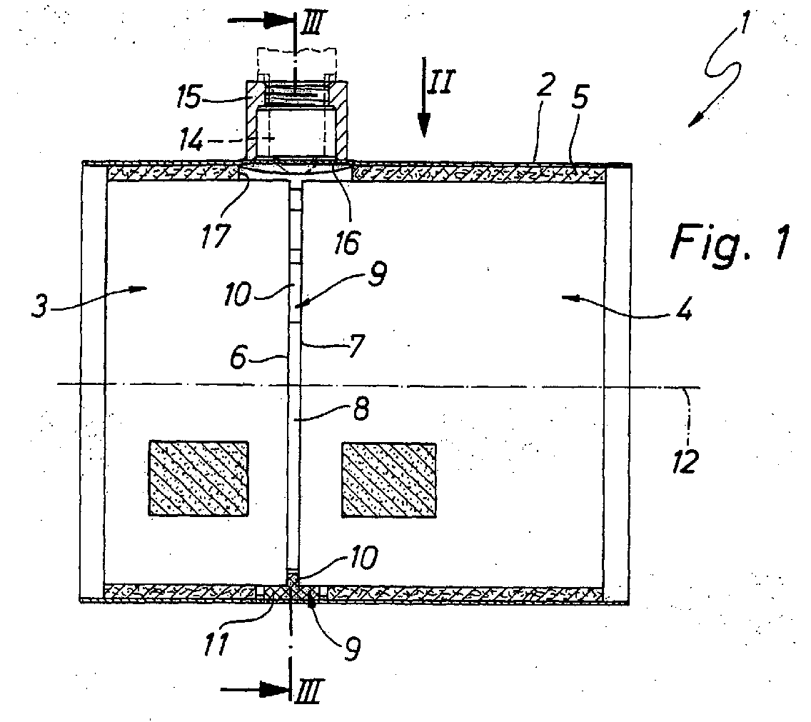
- Multi-bed catalyst 1 a housing 2, in which several, here two, monoliths 3, 4 are housed. Because the multi-bed catalyst 1 in the present example only two monoliths 3, 4 contains, this can also be referred to as a two-bed catalyst become.
- the monoliths 3, 4 suitably have one circular cylindrical body.
- FIGS. 2 and 4 In the views of FIGS. 2 and 4 is for better understanding the housing 2 omitted.
- the two monoliths 3, 4 are designed as catalyst elements, i.e. they are catalytically active.
- Such a multi-bed catalyst 1 is preferably in one Exhaust system of an internal combustion engine, in particular one Motor vehicle used.
- the Storage mat 5 is made of a heat-resistant material and envelops the two monoliths 3, 4 on their circumference.
- the storage mat 2 serves on the one hand for thermal insulation of the Housing 2 compared to the monoliths 3, 4.
- the shock-sensitive monoliths 3, 4, which are usually made of a brittle ceramic are made in the bearing mat 5 softly bedded, i.e. Vibrations of the multi-bed catalytic converter 1 that can occur during operation are from the storage mat 5 steamed.
- the two monoliths 3, 4 are in the housing 2 with respect a flow direction arranged one behind the other, so that they operate in series with the multi-bed catalytic converter 1 be flowed through.
- the two monoliths 3, 4 face each other axial end faces 6, 7 axially spaced from each other, so that a gap 8 axially between the two monoliths 3, 4 is trained.
- a gap 8 axially between the two monoliths 3, 4, here three, spacer elements 9 arranged over which the two monoliths 3.4 axially support each other. Ensure the spacers 9 thus a predetermined minimum axial distance between the two monoliths 3, 4.
- the spacer elements 9 are preferred along the circumference of the monoliths 3, 4 arranged symmetrically, distributed.
- the spacer elements 9 exist made of a heat-resistant material so that it Operating conditions, in particular the operating temperature, withstand the multi-bed catalyst 1.
- the spacer elements arranged on the circumference of the monoliths 3, 4 9 are appropriately dimensioned so that they are radial can be supported on the outside of the housing 2.
- the spacer elements 9 are designed here so that they are one Have a T-shaped axial cross-section (see FIG. 1). In principle, any other suitable cross-sections are possible, for example an L-shaped cross section. In particular with an L-shaped or - as here - with a T-shaped In cross section, each spacer element 9 has a spacer section 10 and a holding section 11.
- the Spacer elements 9 are radially outward on the monoliths 3, 4 arranged, the respective distance section 10 axially radially between the monoliths 3, 4 stretches inside. The spacer sections 10 thus effect compliance with the desired minimum distance between the two monoliths 3, 4.
- the Holding sections 11 each radially outside on the associated Spacer section 10 and radially overlap in axial direction in the T-shaped cross section both monoliths 3, 4 and only one of the monoliths in the case of the L-shaped cross section 3, 4.
- the holding sections 11 are dimensioned so that that they rest radially on the housing 2, so that the monoliths 3, 4 in the area of the gap 8 also over the holding sections 11 of the spacer elements 9 radially on the housing 2 support.
- the spacer elements are 9 each formed by a wire mesh, a suitable, heat-resistant for their manufacture Wire is used.
- the wire mesh of the spacer elements 9 is expediently designed such that the spacer elements 9 on the one hand the desired minimum distance between the two monoliths 3, 4 in all operating states of the Can ensure multiple bed catalyst 1 and the other are sufficiently resilient to thermal expansion effects to compensate.
- the wire mesh be designed so that there is sufficient thermal Insulation between the housing 2 and the monoliths 3, 4 results.
- the spacer elements 9 to the circular cylindrical shape of the monoliths 3, 4 be adjusted so that they are with respect to a longitudinal central axis 12 of the monoliths 3, 4 as circular arc segments, in particular are formed with an arc angle of about 20 °.
- the spacer elements 9 are formed as a knitted fabric they deform accordingly when attached so that they do not have to be preformed.
- the bearing mat 5 has a recess for each spacer element 9 13 in which the respective spacer element 9 supports the bearing mat 5 penetrates radially.
- the given, e.g. punched out, recesses 13 the optimal positions for the spacer elements 9.
- Preferred is, however, an embodiment in which the spacer elements 9 are already attached to the bearing mat 5 before in these the monoliths 3, 4 are used.
- the spacer elements 9 and the bearing mat 5 are expedient designed as separate components. It is basically the same possible to the spacer elements 9 in the bearing mat 5 integrate. Especially when the bearing mat 5 as Knitted fabric, in particular a wire knitted fabric, the spacer elements 9 can be particularly easily with the bearing mat 5 can be connected. The assembly of the multi-bed catalytic converter 1 is further simplified.
- the one between the two monoliths using the spacer elements 9 provided and in terms of its dimension ensured gap 8 can be used for a specific application e.g. are required for an exhaust gas probe 14, which in Fig. 1 is indicated by a broken line.
- an exhaust gas probe 14 can be, for example act an oxygen probe, which is part of a so-called "on-board diagnosis” can be used.
- an exhaust gas probe 14 is the multi-bed catalytic converter 1 here equipped with a suitable connecting piece 15, which is attached to the housing 2 in the area of the gap 8, in particular is welded on.
- connection piece 15 on housing 2 can be simplified on housing 2
- a flat plateau 16 is formed in the area of the gap 8 be on which the connecting piece 15 with a plane End face placed and with the housing 2, in particular is connectable by means of a fillet weld.
- the bearing mat 5 in the area of the connection piece 15 a suitable recess 17 in the form of a radial passage opening.
- this recess 17 can the exhaust probe 14 protrude radially.
- the recess 17 enables proper operation of the exhaust gas probe 14.
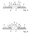
- this protrusion 19 is chosen so that it the recess 13 at the edge in the circumferential direction 18 in each case overlap when the respective spacer 9 in the associated Recess 13 is inserted.
- This design ensures thereby a form-fitting holder of the respective Spacer 9 on the bearing mat 5, at least when installed, if the respective holding section 11 the or the monoliths 3, 4 also overlaps the edge.
- the projections 19 then lie radially on the bearing mat 5, such that radially outer sides of the projections 19 on a radially inner side the bearing mat 5 in the edge region of the recess 13 for contact come.
- the projections 19 can in principle have any shape be appropriate, however, so that the desired positive Fixing the respective spacer 9 on the Bearing mat 5 results in the installed state.
- the projections 19 in the variant according to 6 is designed so that it extends in the circumferential direction 18 rejuvenate.
- the supernatants 19 are here on hers provided with a bevel 20 on the radially inner side, which falls towards the storage mat 5.
- the assembly of the multi-bed catalyst 1 simplified.
- the recesses 13 as in FIGS. 5 and 6 dimensioned slightly larger are called the holding sections 11, which are used for assembly be used in it.
- the assembly of the multi-bed catalytic converter 1 can for example be carried out as follows:
- the storage mat 5 is in the unrolled, flat state the spacer elements 9 equipped. That is, on the radially inner Inside the storage mat 5 are the spacers 9 with their holding sections 11 in the recesses 13 plugged in. Then at least one of the monoliths 3, 4 placed on the bearing mat 5.
- the bearing mat 5 When unrolling the Monoliths 3, 4, the bearing mat 5 simultaneously on the Outer circumference of the monolith 3, 4 wound.
- the holding portions 11 radially outside on the circumference of the monolith 3, 4 to the system, whereby the spacer elements 9 form-fitting are held, namely radially inward through the positive connection between monolith 3, 4 and holding section 11 and radially to the outside through the form fit between the protrusions 19 and the bearing mat 5.
Landscapes
- Chemical & Material Sciences (AREA)
- Engineering & Computer Science (AREA)
- Chemical Kinetics & Catalysis (AREA)
- Combustion & Propulsion (AREA)
- Mechanical Engineering (AREA)
- General Engineering & Computer Science (AREA)
- Health & Medical Sciences (AREA)
- Toxicology (AREA)
- Exhaust Gas After Treatment (AREA)
Abstract
Description
- Fig. 1
- einen axialen Längsschnitt durch einen erfindungsgemäßen Mehrbettkatalysator entsprechend Schnittlinien I in Fig. 2,
- Fig. 2
- eine Draufsicht auf den Mehrbettkatalysator aus Fig. 1 entsprechend einem Ansichtspfeil II in Fig. 1,
- Fig. 3
- einen Querschnitt durch den Mehrbettkatalysator entsprechend Schnittlinien III in Fig. 1,
- Fig. 4
- eine Draufsicht auf den Mehrbettkatalysator entsprechend einem Ansichtspfeil IV in Fig. 3,
- Fig. 5
- eine teilweise geschnittene Seitenansicht auf eine Lagermatte im Bereich eines Distanzelements bei einer besonderen Ausführungsform,
- Fig. 6
- eine Ansicht wie in Fig. 5, jedoch bei einer weiteren Ausführungsform.
Claims (18)
- Mehrbettkatalysator für einen Abgasstrang einer Brennkraftmaschine, insbesondere eines Kraftfahrzeugs,mit einem Gehäuse (2), in dem wenigstens zwei katalytisch wirkende Monolithen (3, 4) axial benachbart und in Reihe durchströmbar angeordnet sind,wobei die beiden Monolithen (3, 4) umfangsseitig von einer gemeinsamen hitzebeständigen Lagermatte (5) umhüllt und über diese im Gehäuse (2) gelagert sind,wobei axial zwischen den beiden Monolithen (3, 4) wenigstens zwei hitzebeständige Distanzelemente (9) umfangsmäßig verteilt angeordnet sind, über die sich die Monolithen (3, 4) axial aneinander abstützen.
- Mehrbettkatalysator nach Anspruch 1,
dadurch gekennzeichnet, dass die Distanzelemente (9) jeweils durch ein Drahtgestrick aus einem hitzebeständigen Draht gebildet sind. - Mehrbettkatalysator nach Anspruch 1 oder 2,
dadurch gekennzeichnet, dass die Distanzelemente (9) radial außen angeordnet sind und sich jeweils mit einem Distanzierabschnitt (10) axial zwischen den Monolithen (3, 4) radial nach innen erstrecken. - Mehrbettkatalysator nach Anspruch 3,
dadurch gekennzeichnet, dass die Distanzelemente (9) jeweils einen radial an den Distanzierabschnitt (10) anschließenden Halteabschnitt (11) aufweisen, der zumindest einen der Monolithen (3, 4) radial außen in axialer Richtung übergreift. - Mehrbettkatalysator nach Anspruch 4,
dadurch gekennzeichnet, dass sich die Monolithen (3, 4) über die Halteabschnitte (11) der Distanzelemente (9) radial am Gehäuse (2) abstützen. - Mehrbettkatalysator nach einem der Ansprüche 1 bis 5,
dadurch gekennzeichnet, dass die Distanzelemente (9) einen L-förmigen oder T-förmigen axialen Querschnitt aufweisen. - Mehrbettkatalysator nach einem der Ansprüche 1 bis 6,
dadurch gekennzeichnet, dass die Distanzelemente (9) bezüglich einer Längsmittelachse (12) der Monolithen (3, 4) als Kreisbogensegmente ausgebildet sind. - Mehrbettkatalysator nach einem der Ansprüche 1 bis 7,
dadurch gekennzeichnet, dass sich die Distanzelemente (9) radial außen am Gehäuse (2) abstützen. - Mehrbettkatalysator nach einem der Ansprüche 1 bis 8,
dadurch gekennzeichnet, dass die Lagermatte (5) für jedes Distanzelement (9) eine Aussparung (13) aufweist, in der das jeweilige Distanzelement (9) angeordnet ist und von der aus sich das jeweilige Distanzelement (9) axial zwischen den Monolithen (3, 4) radial nach innen erstreckt. - Mehrbettkatalysator nach einem der Ansprüche 1 bis 9,
dadurch gekennzeichnet, dass die Distanzelemente (9) in die Lagermatte (5) integriert sind. - Mehrbettkatalysator nach einem der Ansprüche 1 bis 10,
dadurch gekennzeichnet, dass die Lagermatte (5) und die Distanzelemente (9) jeweils als Gestrick aus einem hitzebeständigen Material gebildet und miteinander verbunden sind. - Mehrbettkatalysator nach einem der Ansprüche 1 bis 11,
dadurch gekennzeichnet, dass das Gehäuse (2) in einem Axialabschnitt, in dem die beiden Monolithen (3, 4) durch die Distanzelemente (9) voneinander axial beabstandet sind, einen Anschlußstutzen (15) aufweist, der sich zum Anschluss einer Abgassonde (14) eignet. - Mehrbettkatalysator nach Anspruch 12,
dadurch gekennzeichnet, dass am Gehäuse (2) im Bereich des Anschlußstutzens (15) ein ebenes Plateau (16) ausgebildet ist, an dem der Anschlussstutzen (15) angebracht ist. - Mehrbettkatalysator nach Anspruch 12 oder 13,
dadurch gekennzeichnet, dass die Lagermatte (5) im Bereich des Anschlußstutzens (15) eine Ausnehmung (17) aufweist, in welche eine Abgassonde (14) radial hineinragen kann. - Mehrbettkatalysator zumindest nach Anspruch 4,
dadurch gekennzeichnet, dass bei wenigstens einem Distanzelement (9) der Distanzierabschnitt (10) an wenigstens einer Seite einen in Umfangsrichtung (18) über den Halteabschnitt (11) vorstehenden Überstand (19) aufweist. - Mehrbettkatalysator nach Anspruch 15,
dadurch gekennzeichnet, dass sich der Überstand (19) in Umfangsrichtung verjüngt. - Mehrbettkatalysator nach Anspruch 9 und nach Anspruch 15 oder 16,
dadurch gekennzeichnet, dass zumindest einer der Überstände (19) so dimensioniert ist, dass er im Einbauzustand die Aussparung (13) in Umfangsrichtung (18) randseitig übergreift. - Mehrbettkatalysator nach einem der Ansprüche 15 bis 17,
dadurch gekennzeichnet, dass zumindest einer Überstände (19) im Einbauzustand radial an der Lagermatte (5) anliegt.
Applications Claiming Priority (4)
| Application Number | Priority Date | Filing Date | Title |
|---|---|---|---|
| DE10254036 | 2002-11-20 | ||
| DE10254036A DE10254036B4 (de) | 2002-11-20 | 2002-11-20 | Mehrbettkatalysator |
| DE10301233 | 2003-01-15 | ||
| DE10301233A DE10301233A1 (de) | 2002-11-20 | 2003-01-15 | Mehrbettkatalysator |
Publications (2)
| Publication Number | Publication Date |
|---|---|
| EP1422396A1 true EP1422396A1 (de) | 2004-05-26 |
| EP1422396B1 EP1422396B1 (de) | 2006-09-27 |
Family
ID=32231879
Family Applications (1)
| Application Number | Title | Priority Date | Filing Date |
|---|---|---|---|
| EP03019938A Expired - Lifetime EP1422396B1 (de) | 2002-11-20 | 2003-09-02 | Mehrbettkatalysator |
Country Status (3)
| Country | Link |
|---|---|
| US (1) | US7247280B2 (de) |
| EP (1) | EP1422396B1 (de) |
| DE (1) | DE50305163D1 (de) |
Cited By (3)
| Publication number | Priority date | Publication date | Assignee | Title |
|---|---|---|---|---|
| EP1674683A1 (de) * | 2004-12-27 | 2006-06-28 | Nissan Motor Co., Ltd. | Abgasreinigungsvorrichtung |
| WO2006083397A1 (en) * | 2005-02-01 | 2006-08-10 | Arvin Technologies, Inc. | Converter assembly with insulated sensor boss |
| CN104533578A (zh) * | 2011-01-20 | 2015-04-22 | 揖斐电株式会社 | 保持密封材料、尾气净化装置及尾气净化装置的制造方法 |
Families Citing this family (9)
| Publication number | Priority date | Publication date | Assignee | Title |
|---|---|---|---|---|
| CN100439671C (zh) * | 2004-12-27 | 2008-12-03 | 日产自动车株式会社 | 排气净化装置 |
| DE102004063546A1 (de) * | 2004-12-30 | 2006-07-13 | Emitec Gesellschaft Für Emissionstechnologie Mbh | Wabenkörper mit zumindest teilweise keramischer Wabenstruktur und Aufnahme für Messfühler |
| US8110154B2 (en) * | 2006-02-01 | 2012-02-07 | Katcon Global S.A. | Exhaust treatment device with sensor and method of making |
| US7897117B2 (en) * | 2006-12-01 | 2011-03-01 | Tenneco Automotive Operating Company Inc. | Catalytic converter with mounting device for a hot exhaust gas oxygen sensor |
| US7794672B2 (en) * | 2007-01-11 | 2010-09-14 | Automotive Components Holdings, Llc | Catalytic converter with sensor cavity |
| DE102007042281A1 (de) * | 2007-09-06 | 2009-03-12 | J. Eberspächer GmbH & Co. KG | Verfahren zum Anbringen einer Sonde an einer Abgasbehandlungseinrichtung |
| US8795598B2 (en) * | 2007-09-27 | 2014-08-05 | Katcon Global S.A. | Exhaust treatment device with independent catalyst supports |
| DE202008010058U1 (de) * | 2008-07-25 | 2009-12-03 | Mann+Hummel Gmbh | Luftfiltersystem eines Kraftfahrzeuges |
| JP2012149604A (ja) * | 2011-01-20 | 2012-08-09 | Ibiden Co Ltd | 保持シール材、排ガス浄化装置、及び、排ガス浄化装置の製造方法 |
Citations (8)
| Publication number | Priority date | Publication date | Assignee | Title |
|---|---|---|---|---|
| FR2333950A1 (fr) * | 1973-01-13 | 1977-07-01 | Pforzheim Metallschlauch | Dispositif pour la purification catalytique des gaz brules ou d'echappement |
| JPS562420A (en) * | 1979-06-22 | 1981-01-12 | Nippon Soken Inc | Monolithic catalyst converter |
| JPS61274829A (ja) * | 1985-05-29 | 1986-12-05 | Honda Motor Co Ltd | 触媒コンバ−タの組立方法 |
| EP0283913A2 (de) * | 1987-03-23 | 1988-09-28 | W.R. Grace & Co.-Conn. | Verfahren zum Entfernen von NOx aus Fluidströmen |
| US4864095A (en) * | 1987-07-28 | 1989-09-05 | Honda Giken Kogyo Kabushiki Kaisha | Apparatus for assembling a mesh ring for a catalytic converter |
| DE19627289A1 (de) * | 1996-06-16 | 1997-12-18 | Andreas Dipl Ing Gifhorn | Segmentale Anordnung von Katalysatormonolithen |
| DE19626692A1 (de) * | 1996-07-03 | 1998-01-15 | Zeuna Staerker Kg | Abgasreinigungsvorrichtung für einen Verbrennungsmotor sowie Verfahren zu ihrer Herstellung |
| US6447735B1 (en) * | 1998-04-30 | 2002-09-10 | Nissan Motor Co., Ltd. | Exhaust purifier and manufacturing method of same |
Family Cites Families (8)
| Publication number | Priority date | Publication date | Assignee | Title |
|---|---|---|---|---|
| DE2243251B2 (de) * | 1972-09-02 | 1976-01-02 | Paul Gillet Gmbh, 6732 Edenkoben | Vorrichtung zur Reinigung der Abgase von Brennkraftmaschinen |
| DE2442488A1 (de) | 1974-09-05 | 1976-03-18 | Daimler Benz Ag | Vorrichtung zur katalytischen reinigung der auspuffgase von brennkraftmaschinen, insbesondere von kraftfahrzeugbrennkraftmaschinen |
| JPS5724886Y2 (de) * | 1979-03-19 | 1982-05-29 | ||
| DE3729994A1 (de) | 1987-09-08 | 1989-03-16 | Bischoff Erhardt Gmbh Co Kg | Vorrichtung zum katalytischen reinigen von abgasen |
| DE4024015A1 (de) | 1990-07-28 | 1992-02-06 | Boysen Friedrich Gmbh Co Kg | Vorrichtung zur katalytischen reinigung bzw. zerlegung von heissen abgasen |
| DE19511503A1 (de) | 1994-12-30 | 1996-07-04 | Eberspaecher J | Abgasbehandlungsvorrichtung für Verbrennungsmotorenabgase |
| US6001314A (en) * | 1997-09-15 | 1999-12-14 | General Motors Corporation | Catalytic converter housing with deep drawn shells |
| DE19753196A1 (de) | 1997-12-01 | 1999-07-08 | Eisu Innovative Ges Fuer Techn | Biosorbentien auf der Basis cellulosehaltiger Materialien |
-
2003
- 2003-09-02 DE DE50305163T patent/DE50305163D1/de not_active Expired - Lifetime
- 2003-09-02 EP EP03019938A patent/EP1422396B1/de not_active Expired - Lifetime
- 2003-10-10 US US10/683,755 patent/US7247280B2/en not_active Expired - Fee Related
Patent Citations (8)
| Publication number | Priority date | Publication date | Assignee | Title |
|---|---|---|---|---|
| FR2333950A1 (fr) * | 1973-01-13 | 1977-07-01 | Pforzheim Metallschlauch | Dispositif pour la purification catalytique des gaz brules ou d'echappement |
| JPS562420A (en) * | 1979-06-22 | 1981-01-12 | Nippon Soken Inc | Monolithic catalyst converter |
| JPS61274829A (ja) * | 1985-05-29 | 1986-12-05 | Honda Motor Co Ltd | 触媒コンバ−タの組立方法 |
| EP0283913A2 (de) * | 1987-03-23 | 1988-09-28 | W.R. Grace & Co.-Conn. | Verfahren zum Entfernen von NOx aus Fluidströmen |
| US4864095A (en) * | 1987-07-28 | 1989-09-05 | Honda Giken Kogyo Kabushiki Kaisha | Apparatus for assembling a mesh ring for a catalytic converter |
| DE19627289A1 (de) * | 1996-06-16 | 1997-12-18 | Andreas Dipl Ing Gifhorn | Segmentale Anordnung von Katalysatormonolithen |
| DE19626692A1 (de) * | 1996-07-03 | 1998-01-15 | Zeuna Staerker Kg | Abgasreinigungsvorrichtung für einen Verbrennungsmotor sowie Verfahren zu ihrer Herstellung |
| US6447735B1 (en) * | 1998-04-30 | 2002-09-10 | Nissan Motor Co., Ltd. | Exhaust purifier and manufacturing method of same |
Non-Patent Citations (2)
| Title |
|---|
| PATENT ABSTRACTS OF JAPAN vol. 0050, no. 47 (M - 061) 28 March 1981 (1981-03-28) * |
| PATENT ABSTRACTS OF JAPAN vol. 0111, no. 35 (M - 585) 28 April 1987 (1987-04-28) * |
Cited By (5)
| Publication number | Priority date | Publication date | Assignee | Title |
|---|---|---|---|---|
| EP1674683A1 (de) * | 2004-12-27 | 2006-06-28 | Nissan Motor Co., Ltd. | Abgasreinigungsvorrichtung |
| US7356986B2 (en) | 2004-12-27 | 2008-04-15 | Nissan Motor Co., Ltd. | Exhaust gas purification device |
| WO2006083397A1 (en) * | 2005-02-01 | 2006-08-10 | Arvin Technologies, Inc. | Converter assembly with insulated sensor boss |
| US7452512B2 (en) | 2005-02-01 | 2008-11-18 | Et Us Holdings Llc | Converter assembly with insulated sensor boss |
| CN104533578A (zh) * | 2011-01-20 | 2015-04-22 | 揖斐电株式会社 | 保持密封材料、尾气净化装置及尾气净化装置的制造方法 |
Also Published As
| Publication number | Publication date |
|---|---|
| US20040105792A1 (en) | 2004-06-03 |
| US7247280B2 (en) | 2007-07-24 |
| EP1422396B1 (de) | 2006-09-27 |
| DE50305163D1 (de) | 2006-11-09 |
Similar Documents
| Publication | Publication Date | Title |
|---|---|---|
| DE2823549C3 (de) | Vorrichtung zur katalytischen Gasbehandlung | |
| EP1887194A1 (de) | Abgasreinigungseinrichtung | |
| EP1422396B1 (de) | Mehrbettkatalysator | |
| EP1437490B1 (de) | Abgasbehandlungseinrichtung | |
| DE3700070A1 (de) | Vorrichtung fuer die katalytische reinigung von fahrzeugmotor-abgasen | |
| EP0537603B1 (de) | Doppelwandiges luftisoliertes Rohr für Abgasanlagen in Fahrzeugen | |
| EP2105588A1 (de) | Abgasbehandlungseinrichtung | |
| DE69301107T2 (de) | Vorrichtung zur Reinigung von Abgasen | |
| EP4198274B1 (de) | Heizeinrichtung zum beheizen eines gasstroms | |
| EP0471175A1 (de) | Verfahren zur Herstellung einer Vorrichtung zur katalytischen Reinigung bzw. Zerlegung von heissen Abgasen | |
| EP1019617A1 (de) | Wabenkörperanordnung mit tragabschnitten | |
| DE102012017178A1 (de) | Abgasreinigungsvorrichtung | |
| DE602005004455T2 (de) | Gasbehandlungseinrichtung und Verfahren zu deren Herstellung und deren Verwendung | |
| DE10254036B4 (de) | Mehrbettkatalysator | |
| DE4417407C1 (de) | Flexible Verbindungsanordnung für zwei Rohrteile, insbesondere bei Abgasanlagen von Kraftfahrzeugen | |
| EP0561019B1 (de) | Vorrichtung zur Lagefixierung einer Innenschale in einem Gehäuse einer Abgasanlage für Fahrzeuge | |
| DE2400443A1 (de) | Vorrichtung zum reinigen der abgase von brennkraftmaschinen | |
| EP2913495B1 (de) | Verfahren zum Herstellen einer Abgasnachbehandlungseinrichtung und entsprechende Abgasnachbehandlungseinrichtung | |
| DE3926072A1 (de) | Katalysator zur abgasreinigung mit elastischen elementen zum ausgleich von laengsdehnungen | |
| DE3922667A1 (de) | Vorrichtung zur katalytischen entgiftung oder dgl. von verbrennungsmotor-abgasen mit doppelwandigem gehaeuse | |
| DE10301233A1 (de) | Mehrbettkatalysator | |
| DE2341265C2 (de) | Einrichtung zur katalytischen Abgasreinigung | |
| DE3203237A1 (de) | Abgasfilter fuer verbrennungsmotoren | |
| EP0174919A2 (de) | Katalytische Abgasreinigungseinrichtung | |
| DE2752716A1 (de) | Katalysatorbehaelter |
Legal Events
| Date | Code | Title | Description |
|---|---|---|---|
| PUAI | Public reference made under article 153(3) epc to a published international application that has entered the european phase |
Free format text: ORIGINAL CODE: 0009012 |
|
| AK | Designated contracting states |
Kind code of ref document: A1 Designated state(s): AT BE BG CH CY CZ DE DK EE ES FI FR GB GR HU IE IT LI LU MC NL PT RO SE SI SK TR |
|
| AX | Request for extension of the european patent |
Extension state: AL LT LV MK |
|
| 17P | Request for examination filed |
Effective date: 20040609 |
|
| AKX | Designation fees paid |
Designated state(s): DE FR GB IT |
|
| 17Q | First examination report despatched |
Effective date: 20050704 |
|
| GRAP | Despatch of communication of intention to grant a patent |
Free format text: ORIGINAL CODE: EPIDOSNIGR1 |
|
| GRAS | Grant fee paid |
Free format text: ORIGINAL CODE: EPIDOSNIGR3 |
|
| GRAA | (expected) grant |
Free format text: ORIGINAL CODE: 0009210 |
|
| AK | Designated contracting states |
Kind code of ref document: B1 Designated state(s): DE FR GB IT |
|
| REG | Reference to a national code |
Ref country code: GB Ref legal event code: FG4D Free format text: NOT ENGLISH |
|
| REF | Corresponds to: |
Ref document number: 50305163 Country of ref document: DE Date of ref document: 20061109 Kind code of ref document: P |
|
| GBT | Gb: translation of ep patent filed (gb section 77(6)(a)/1977) |
Effective date: 20061102 |
|
| ET | Fr: translation filed | ||
| PLBE | No opposition filed within time limit |
Free format text: ORIGINAL CODE: 0009261 |
|
| STAA | Information on the status of an ep patent application or granted ep patent |
Free format text: STATUS: NO OPPOSITION FILED WITHIN TIME LIMIT |
|
| 26N | No opposition filed |
Effective date: 20070628 |
|
| PGFP | Annual fee paid to national office [announced via postgrant information from national office to epo] |
Ref country code: IT Payment date: 20080925 Year of fee payment: 6 |
|
| PGFP | Annual fee paid to national office [announced via postgrant information from national office to epo] |
Ref country code: FR Payment date: 20100331 Year of fee payment: 7 |
|
| PGFP | Annual fee paid to national office [announced via postgrant information from national office to epo] |
Ref country code: DE Payment date: 20100226 Year of fee payment: 7 Ref country code: GB Payment date: 20100324 Year of fee payment: 7 |
|
| PG25 | Lapsed in a contracting state [announced via postgrant information from national office to epo] |
Ref country code: IT Free format text: LAPSE BECAUSE OF NON-PAYMENT OF DUE FEES Effective date: 20090902 |
|
| GBPC | Gb: european patent ceased through non-payment of renewal fee |
Effective date: 20100902 |
|
| REG | Reference to a national code |
Ref country code: FR Ref legal event code: ST Effective date: 20110531 |
|
| REG | Reference to a national code |
Ref country code: DE Ref legal event code: R119 Ref document number: 50305163 Country of ref document: DE Effective date: 20110401 |
|
| PG25 | Lapsed in a contracting state [announced via postgrant information from national office to epo] |
Ref country code: DE Free format text: LAPSE BECAUSE OF NON-PAYMENT OF DUE FEES Effective date: 20110401 Ref country code: FR Free format text: LAPSE BECAUSE OF NON-PAYMENT OF DUE FEES Effective date: 20100930 |
|
| PG25 | Lapsed in a contracting state [announced via postgrant information from national office to epo] |
Ref country code: GB Free format text: LAPSE BECAUSE OF NON-PAYMENT OF DUE FEES Effective date: 20100902 |