EP1422088A1 - Dispositif permettant de commander l'écoulement d'un fluide et d'orienter cet écoulement dans une direction déterminée - Google Patents
Dispositif permettant de commander l'écoulement d'un fluide et d'orienter cet écoulement dans une direction déterminée Download PDFInfo
- Publication number
- EP1422088A1 EP1422088A1 EP03356182A EP03356182A EP1422088A1 EP 1422088 A1 EP1422088 A1 EP 1422088A1 EP 03356182 A EP03356182 A EP 03356182A EP 03356182 A EP03356182 A EP 03356182A EP 1422088 A1 EP1422088 A1 EP 1422088A1
- Authority
- EP
- European Patent Office
- Prior art keywords
- ring
- nozzle
- wall
- fluid
- conduit
- Prior art date
- Legal status (The legal status is an assumption and is not a legal conclusion. Google has not performed a legal analysis and makes no representation as to the accuracy of the status listed.)
- Granted
Links
Images
Classifications
-
- B—PERFORMING OPERATIONS; TRANSPORTING
- B60—VEHICLES IN GENERAL
- B60H—ARRANGEMENTS OF HEATING, COOLING, VENTILATING OR OTHER AIR-TREATING DEVICES SPECIALLY ADAPTED FOR PASSENGER OR GOODS SPACES OF VEHICLES
- B60H1/00—Heating, cooling or ventilating devices
- B60H1/34—Nozzles; Air-diffusers
- B60H1/3414—Nozzles; Air-diffusers with means for adjusting the air stream direction
- B60H1/3435—Nozzles; Air-diffusers with means for adjusting the air stream direction using only a pivoting frame
- B60H1/3442—Nozzles; Air-diffusers with means for adjusting the air stream direction using only a pivoting frame the frame being spherical
Definitions
- the present invention relates to a device for control the flow of a fluid and direct this flow in a determined direction.
- This device can in particular be an aerator for passenger compartment of a motor vehicle.
- the nozzle is thus movable in pivoting around two axes, the first of which is perpendicular to the axis of the duct (pivoting of the nozzle relative to the ring) and of which a second is parallel to the axis of the duct (pivoting of the nozzle - ring assembly relative to the body).
- the first of these pivoting movements allows opening or closing the duct and adjusting the orientation of the fluid in a plane, for example the horizontal plane in the passenger compartment of a motor vehicle, for an orientation of the air flow to the left towards the right ;
- the second of these pivoting movements allows modify the orientation of said first axis in the plane of the ring, to modify the orientation of the plane in which the nozzle pivots, and therefore the orientation of the fluid flow, for example to pass from said orientation of the flow to the left or to the right at an orientation of this flow in a vertical plane relative to the passenger compartment of the vehicle, therefore towards the up or down.
- This aerator thus makes it possible to control the flow of a fluid and the orientation of this flow in an infinity of directions, by combination of the two aforementioned movements, while presenting a particularly simple structure, consisting of a reduced number of parts.
- the nozzle can be in one piece.
- the nozzle generally comprises a spherical envelope, and consists of several stepped circular walls and a wall located in the middle position; the peripheral edge of this wall located at middle position is shaped so as to cooperate, in two nozzle pivot positions approximately 180 ° apart relative to each other, with the inner face of the ring to achieve the the air intake of the device is closed.
- the ring bearing the nozzle is usually formed by two materials different thermoplastics which are injected in turn in the same mold, by the well known bi-injection technique.
- the first material which makes it possible to carry out the core of the ring is chosen for its mechanical resistance properties, and its low cost. Typically, polypropylene is used.
- the second material that is used is chosen for its properties elasticity to improve the pivoting of the ring inside the body of fluid flow duct, as well as the sealing at the ring / body interface of the flow conduit.
- This material is by example a Santoprene® type elastomer.
- the objective of the present invention is to solve this problem by proposing a device for controlling the flow of a fluid, for example air, keeping all its properties intact functional, even when said device is subjected to strong thermal variations, and do not require manufacturing tolerances very strict.
- the invention is characterized in that the ring has, on its internal surface, in the zone of contact with the central wall of the nozzle, at least one first flexible and flexible lip intended to come into contact with said central wall when the nozzle is tilted in the closed position of the conduit, and in that the ring has at least one second flexible and flexible lip on its periphery external, in contact with the flow conduit, said second lip preferably being molded from the same material as the first lip.
- the two lips belong to the same room.
- Each lip is not only flexible, but also flexible, which allows, when passing the hard point when the user wish to close the air intake, to realize a bending deformation of the lip, and no longer an elongated deformation of the entire ring.
- the core of the ring is made in one rigid thermoplastic of polypropylene type, and the first and second lips are made of a thermoplastic elastomer of the type Santoprene®, the two materials being molded in the same mold by a bi-injection process.
- Other elastomeric materials can nevertheless be used.
- the body comprises a clean annular seat to receive the ring with possibility of axial pivoting around the axis of ring revolution, and a latching assembly, the thickness of the ring being such that, when this ring is in abutment against the seat, the side of the ring opposite this seat is locked in the opposite direction axial by said latching assembly.
- each latching assembly comprises two slots arranged in axially offset diametrical planes and a prominence with an inclined wall, projecting radially inwards from the body and located between the slots, the thickness of the body wall being such that the portion of wall situated between these slots is deformable in the direction radial, to allow movement of the prominence between a position radially internal, in which this prominence can ensure the ring lock, and a clear position, in which this prominence allows the passage of the ring beyond it.
- the nozzle and the ring comprise snap-in means for simple engagement engagement of said respective mounting means of this ring and of the nozzle.
- the means for latching the nozzle and the ring comprise preferably two cylindrical cavities of the ring, diametrically opposite, each of which opens into the inner face of the ring, at level of a recess arranged therein, and further comprise two diametrically opposed nozzle journals projecting from the middle wall, one of these pins being intended to be engaged in one cavities of the ring and the other journal is intended to be pressed against the ring until slightly deform it radially, towards the outside, to allow this other journal to be engaged in the other cavity of the ring.
- each recess defines two surfaces of support, on both sides of the opening of the cavity of the ring emerging in this recess, and each pin is bordered, at the level from its base, by a lug extending radially with respect to it, each lug cooperating with one of said bearing surfaces to stop the swivel movement of the nozzle when it is in a of said device closing positions.
- the stepped circular walls and the wall located in position median are preferably connected to each other by three sails, of which the one located in the middle position has a planar shape and of which the two located in the lateral position have curved shapes.
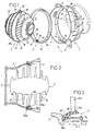
- the figures represent from different angles an aerator 1, comprising a body 2, a ring 3 and an air diffusion nozzle 4.
- All of these parts 2, 3, 4 are made of material suitable synthetic, such as polypropylene.
- the body 2 has a flared tubular shape and delimits a air flow duct 7.
- This body 2 is intended to be fixed to a wall (not shown), in particular the vehicle dashboard, by one of its ends, by means of legs 8, and its other end is intended to be connected to a conduit (not shown) for routing air.
- this body 2 has an annular seat 10, suitable for receiving the ring 3 with possibility of pivoting, and three sets of snap distributed on its circumference.
- Each of these sets includes two slots 11 arranged in axially offset diametrical planes and a prominence 12 inclined wall, projecting radially on the inside of the body 2 and located between the slots 11.
- the thickness of the wall of the body 2 is such that the portions of wall located between the slots 11 are deformable in the radial direction, to allow the movement of the prominences 12, between their position equilibrium in which they project towards the inside of the duct 7, and a position of erasure in which these prominences 12 authorize the passage of the ring 3 beyond them.
- the ring 3 has an outside diameter such that it can be engaged in the body 2 until its axial end face turned towards seat 10 come to bear against this seat 10.
- the ring 3 comprises a protruding flange 15 outward, clean, when ring 3 is engaged in the body 2, to lean against the prominences 12 then to erase them by moving them radially.
- the thickness of the ring 3 is such that, when this ring 3 is in abutment against the seat 10, the axial face opposite end is beyond said prominences 12. The latter can therefore, in this position of the ring 3, return in their normal position, and lock the ring 3 between them and said seat 10 while allowing the ring 3 to pivot relative to the body 2.
- the ring 3 also includes two cylindrical cavities 20 diametrically opposite. Each of these cavities 20 opens into the inner face of the ring, at a recess 21 arranged in this one. This recess 21 delimits two bearing surfaces 22, on the side and on the other side of the opening of the cavity 20.
- the ring 3 has a bi-material structure, and comprises a base 3a in a relatively material rigid, for example in propylene, and overmolding 3b in a material flexible, for example a Santoprene® type polymer, intended to nozzle contact 4.
- the ring 3 forms a seat 23 for receiving a central wall 25a that includes the nozzle 4.
- the ring 3 has on its internal surface, in the area of contact with the middle wall 25a of the nozzle 4, a first flexible lip and flexible 24a intended to come into contact with said central wall when the nozzle is tilted in the closed position of the duct 7.
- Said first lip 24a is made of a material with high holding properties in temperature, of the Santoprene® type.
- the ring has a second flexible and flexible lip 24b, on its outer periphery, in contact with the conduit body flow, said second lip being molded from the same material to higher temperature resistance properties than the first lip 24a.
- the core of the ring is made of a rigid thermoplastic of polypropylene type, and the first and second lips are made in one Santoprene® type thermoplastic elastomer, the two materials being molded in the same mold by a bi-injection process.
- the nozzle 4 has a generally spherical envelope, and consists of six stepped circular walls 25, and by said wall 25a located in the middle position.
- These walls 25 and 25a are connected to each other by three sails 26, 27, of which the one situated in the middle position has a planar shape and both of which located in the lateral position have curved shapes.
- the nozzle 4 further comprises two journals 30 diametrically opposite, shown in Figure 1, projecting from the wall 25a.
- Each pin 30 is bordered, at its base, by a lug 31 extending radially with respect to it and has a lug 32 projecting from its axial end face.
- one of the pins 30 is intended to be engaged in one of the cavities 20 then the other pin 30 is pressed against the ring 3 until slightly deform it radially outward to allow to engage this other pin 30 in the other cavity 20.
- This engagement authorizes the return of the ring 3 to its neutral form, which allows the locking the pin 30 in the cavity 20.
- the lug 32 protrudes beyond of the outer face of the ring 3 in order to ensure this locking.
- pins 30 and cavities 20 allow the tilting of the nozzle 4 with respect to the ring 3, between two closing positions of aerator 1 spaced approximately 180 ° apart, in which the peripheral edge of the wall 25a is in contact with or is close to the face inner of the ring 3.
- the nozzle 4 can be placed in a plurality of intermediate positions between these closed positions, in which said peripheral edge is distant from said internal face, which allows the passage of the air flow between this edge and this face and corresponds to the opening of the aerator 1. This plurality of opening positions allows to adjust the orientation of the air flow in a plane perpendicular to the axis passing through the pins 30.
- Each lug 31 cooperates, in one or the other of said closed positions, with one of the bearing surfaces 22 to stop the pivoting movement of the nozzle 4 when the latter is in one of these closed position.
- the nozzle 4 is mounted on the ring 3, by engagement then snap-fastening, in the manner above, pins 30 in the cavities 20.
- the assembly is then engaged in the body 2 until the ring 3 bears against the prominences 12 and then radially erases these, and until this ring 3 comes into contact with seat 10.
- the prominences 12 allow the locking of the ring 3 in the body 2, with the possibility of pivoting thereof around the axis of the duct 7.
- the nozzle 4 is thus movable in pivoting around two axes, a first of which is perpendicular to the axis of conduit 7 (pivoting of the nozzle 4 relative to the ring 3) and a second of which is confused with the axis of the duct 7 (pivoting of the nozzle 4 - ring 3 assembly by relation to the body 2).
- axis of the conduit is meant the axis of the conduit at level of its section which receives the ring.
- the first of these movements allows the opening or closing the duct and adjusting the orientation of the air flow in the plane perpendicular to the axis passing through the pins 30. It can for example be a horizontal plane in the passenger compartment of a motor vehicle, to an orientation of the air flow to the left or to the right.
- the second of these movements allows you to modify the orientation of said axis in the plane of the ring 3, to modify the orientation relative to the body 2 of the plane in which the nozzle 4 pivots, and therefore the orientation of the air flow.
- This modification can by example to go from said flow orientation to the left or to the right at an orientation of this flow in a vertical plane with respect inside the vehicle, so up or down. all orientation of the nozzle 4 combining these two movements is however possible.
- the invention provides a device for controlling the flow of a fluid and for directing this flow, having in particular the advantage, in addition to these functions, of present a particularly simple structure, consisting of at least three rooms, unlike existing aerators, which include each six pieces or more.
- the structure of the lips soft and flexible in shape circular allows them to easily comply with the periphery of the wall, which improves the tightness all the more.
Landscapes
- Physics & Mathematics (AREA)
- Thermal Sciences (AREA)
- Engineering & Computer Science (AREA)
- Mechanical Engineering (AREA)
- Air-Flow Control Members (AREA)
- Flow Control (AREA)
- Container, Conveyance, Adherence, Positioning, Of Wafer (AREA)
- Control Of Vending Devices And Auxiliary Devices For Vending Devices (AREA)
- Nozzles (AREA)
- Jet Pumps And Other Pumps (AREA)
- Structures Of Non-Positive Displacement Pumps (AREA)
Abstract
Description
- un corps délimitant un conduit d'écoulement du fluide ;
- une buse de diffusion de fluide, et
- des moyens de montage respectifs aménagés sur le corps et sur la buse, permettant le montage pivotant de cette buse dans ce corps, entre une position de fermeture du dispositif, dans laquelle la buse obture ledit conduit, et une pluralité de positions d'ouverture du dispositif, dans lesquelles la buse laisse passer le fluide entre elle et le conduit, la buse pouvant être placée dans chacune de ces positions d'ouverture pour permettre le réglage de la direction d'écoulement du fluide, lesdits moyens de montage comprenant un anneau monté dans le corps de manière pivotante autour d'un axe sensiblement parallèle à l'axe du conduit, et des moyens de montage aménagés sur cet anneau, propres à coopérer avec les moyens de montage que comprend la buse pour permettre le montage de cette buse sur cet anneau avec possibilité de pivotement autour d'un axe perpendiculaire à l'axe dudit conduit.
- un corps délimitant un conduit d'écoulement du fluide ;
- une buse de diffusion de fluide, et
- des moyens de montage respectifs aménagés sur le corps et sur la buse, permettant le montage pivotant de cette buse dans ce corps, entre une position de fermeture du dispositif, dans laquelle la buse obture ledit conduit, et une pluralité de positions d'ouverture du dispositif, dans lesquelles la buse laisse passer le fluide entre elle et le conduit, la buse pouvant être placée dans chacune de ces positions d'ouverture pour permettre le réglage de la direction d'écoulement du fluide ;
la buse présentant une enveloppe généralement sphérique, et étant constituée par plusieurs parois circulaires étagées et par une paroi située en position médiane ; le bord périphérique de cette paroi située en position médiane étant conformé de manière à venir coopérer, dans deux positions de pivotement de la buse distantes de sensiblement 180° l'une par rapport à l'autre, avec la face interne de l'anneau pour réaliser la fermeture du dispositif.
Claims (10)
- Dispositif (1) permettant de commander l'écoulement d'un fluide et d'orienter cet écoulement dans une direction déterminée, comprenant :lesdits moyens de montage comprenant un anneau (3) monté dans le corps (2) de manière pivotante autour d'un axe sensiblement confondu avec l'axe du conduit (7), et des moyens de montage (20) aménagés sur cet anneau (3), propres à coopérer avec les moyens de montage (30) que comprend la buse (4) pour permettre le montage de cette buse (4) sur cet anneau (3) avec possibilité de pivotement autour d'un axe perpendiculaire à l'axe dudit conduit (7) ;un corps (2) délimitant un conduit (7) d'écoulement du fluide ;une buse (4) de diffusion de fluide, etdes moyens de montage respectifs (3, 12, 20, 30) aménagés sur le corps (2) et sur la buse (4), permettant le montage pivotant de cette buse (4) dans ce corps (2), entre une position de fermeture du dispositif (1), dans laquelle la buse (4) obture ledit conduit (7), et une pluralité de positions d'ouverture du dispositif (1), dans lesquelles la buse (4) laisse passer le fluide entre elle et le conduit (7), la buse (4) pouvant être placée dans chacune de ces positions d'ouverture pour permettre le réglage de la direction d'écoulement du fluide ;
la buse (4) présentant une enveloppe généralement sphérique, et étant constituée par plusieurs parois circulaires étagées (25) et par une paroi (25a) située en position médiane ; le bord périphérique de cette paroi (25a) située en position médiane étant conformé de manière à venir coopérer, dans deux positions de pivotement de la buse (4) distantes de sensiblement 180° l'une par rapport à l'autre, avec la face interne de l'anneau (3) pour réaliser la fermeture du dispositif (1),
dispositif caractérisé en ce que l'anneau (3) comporte, sur sa surface interne, dans la zone de contact avec la paroi médiane (25a) de la buse (4), au moins une première lèvre souple et flexible (24a) destinée à entrer en contact avec ladite paroi médiane lorsque la buse est basculée en position de fermeture du conduit (7), et en ce que l'anneau comporte au moins une seconde lèvre souple et flexible (24b), sur sa périphérie externe, en contact avec le conduit d'écoulement. - Dispositif selon la revendication 1, caractérisé en ce que ladite seconde lèvre (24b) est moulée dans le même matériau que la première lèvre (24a).
- Dispositif selon les revendications 1 ou 2, caractérisé en ce que les deux lèvres (24a, 24b) appartiennent à la même pièce.
- Dispositif selon l'une des revendications 1 à 3, caractérisé en ce que l'âme de l'anneau est réalisée en un thermoplastique rigide de type polypropylène, et en ce que les première (24a) et seconde (24b) lèvres sont réalisées en un élastomère thermoplastique de type Santoprène®, les deux matériaux étant moulés dans le même moule par un procédé de bi-injection.
- Dispositif selon l'une des revendications 1 à 4, caractérisé en ce que le corps (2) comprend un siège annulaire (10) propre à recevoir l'anneau (3) avec possibilité de pivotement axial autour de l'axe de révolution de l'anneau, et un ensemble d'encliquetage (11, 12), l'épaisseur de l'anneau (3) étant telle que, lorsque cet anneau (3) est en appui contre le siège, la côté de l'anneau (3) situé à l'opposé de ce siège est verrouillé dans le sens axial par ledit ensemble d'encliquetage (12).
- Dispositif selon la revendication 5, caractérisé en ce que chaque ensemble d'encliquetage (11, 12) comprend deux fentes (11) aménagées dans des plans diamétraux axialement décalés et une proéminence (12) à paroi inclinée, faisant saillie radialement vers l'intérieur du corps (2) et située entre les fentes (11), l'épaisseur de la paroi du corps (2) étant telle que la portion de paroi située entre ces fentes (11) est déformable dans le sens radial, pour permettre le mouvement de la proéminence (12) entre une position radialement interne, dans laquelle cette proéminence (12) peut assurer le verrouillage de l'anneau (3), et une position d'effacement, dans laquelle cette proéminence (12) autorise le passage de l'anneau (3) au-delà d'elle.
- Dispositif selon les revendications 1 à 6, caractérisé en ce que la buse (4) et l'anneau (3) comprennent des moyens à encliquetage (20, 21, 30), permettant d'amener en prise par simple enclenchement lesdits moyens de montage respectifs (20, 30) de cet anneau (3) et de la buse (4).
- Dispositif selon la revendication 7, caractérisé en ce que les moyens d'encliquetage de la buse et de l'anneau comprennent deux cavités cylindriques (20) de l'anneau, diamétralement opposées, dont chacune débouche dans la face interne de l'anneau (3), au niveau d'un évidement (21) aménagé dans celui-ci, et comprennent en outre deux tourillons (30) de la buse (4), diamétralement opposés, faisant saillie de la paroi médiane (25a), l'un de ces tourillons (30) étant destiné à être engagé dans l'une des cavités (20) de l'anneau (3) et l'autre tourillon (30) est destiné à être pressé contre l'anneau (3) jusqu'à légèrement déformer celui-ci dans le sens radial, vers l'extérieur, pour permettre d'engager cet autre tourillon (30) dans l'autre cavité (20) de l'anneau (3).
- Dispositif selon la revendication 8, caractérisé en ce que chaque évidement (21) délimite deux surfaces d'appui (22), de part et d'autre de l'ouverture de la cavité (20) de l'anneau (3) débouchant dans cet évidement (21), et en ce que chaque tourillon (30) est bordé, au niveau de sa base, par un ergot (31) s'étendant radialement par rapport à lui, chaque ergot (31) venant coopérer avec l'une desdites surfaces d'appui (22) pour arrêter le mouvement de pivotement de la buse (4) lorsque celle-ci se trouve dans une desdites positions de fermeture du dispositif.
- Dispositif selon l'une des revendications 1 à 9, caractérisé en ce que lesdites parois circulaires étagées (25) et ladite paroi située en position médiane (25a) sont reliées les unes aux autres par trois voiles (26, 27), dont celui situé en position médiane a une forme plane et dont les deux situés en position latérale ont des formes courbes.
Applications Claiming Priority (2)
| Application Number | Priority Date | Filing Date | Title |
|---|---|---|---|
| FR0214453 | 2002-11-19 | ||
| FR0214453A FR2847206B1 (fr) | 2002-11-19 | 2002-11-19 | Dispositif permettant de commander l'ecoulement d'un fluide et d'orienter cet ecoulement dans une direction determinee |
Publications (2)
| Publication Number | Publication Date |
|---|---|
| EP1422088A1 true EP1422088A1 (fr) | 2004-05-26 |
| EP1422088B1 EP1422088B1 (fr) | 2006-04-05 |
Family
ID=32187718
Family Applications (1)
| Application Number | Title | Priority Date | Filing Date |
|---|---|---|---|
| EP03356182A Expired - Lifetime EP1422088B1 (fr) | 2002-11-19 | 2003-11-19 | Dispositif permettant de commander l'écoulement d'un fluide et d'orienter cet écoulement dans une direction déterminée |
Country Status (5)
| Country | Link |
|---|---|
| EP (1) | EP1422088B1 (fr) |
| AT (1) | ATE322393T1 (fr) |
| DE (1) | DE60304419T2 (fr) |
| ES (1) | ES2260592T3 (fr) |
| FR (1) | FR2847206B1 (fr) |
Cited By (3)
| Publication number | Priority date | Publication date | Assignee | Title |
|---|---|---|---|---|
| EP1793180A1 (fr) * | 2005-11-30 | 2007-06-06 | Dr. Schneider Kunststoffwerke GmbH | Buse d'aération dotée de lamelles horizontales et/ou verticales |
| FR2902702A1 (fr) * | 2006-06-27 | 2007-12-28 | Key Plastics Internat Snc | Aerateur pour vehicule automobile comprenant deux ensembles d'ailettes de reglage |
| US20140030974A1 (en) * | 2011-02-02 | 2014-01-30 | Behr Gmbh & Co. Kg | Air nozzle |
Families Citing this family (4)
| Publication number | Priority date | Publication date | Assignee | Title |
|---|---|---|---|---|
| ES1061179Y (es) * | 2005-07-13 | 2006-05-16 | Seat Sa | Difusor de aire para salpicaderos de vehiculos |
| FR2889114B1 (fr) | 2005-08-01 | 2011-04-29 | Key Plastics Int | Aerateur, notamment pour automobile, comprenant des ailettes de reglage pivotantes montees sur un corps rotatif |
| FR2892342B1 (fr) | 2005-10-21 | 2012-05-25 | Bourbon Automobile Sa | Dispositif permettant de commander l'ecoulement d'un fluide et d'orienter cet ecoulement dans une direction determinee |
| DE102011009423B4 (de) | 2011-01-26 | 2017-07-20 | GM Global Technology Operations LLC (n. d. Ges. d. Staates Delaware) | Montagehilfe für eine Belüftungsdüse und einen Belüftungskanal eines Kraftfahrzeuges, Belüftungsdüse, Belüftungskanal und Armaturentafel |
Citations (2)
| Publication number | Priority date | Publication date | Assignee | Title |
|---|---|---|---|---|
| DE1942687U (de) * | 1965-05-11 | 1966-07-21 | Ferodo Sa | Geblaese- oder belueftugnsmuendung, insbesondere fuer kraftfahrzeuge. |
| FR2806968A1 (fr) * | 2000-04-03 | 2001-10-05 | Bourbon Automobile Sa | Dispositif permettant de commander l'ecoulement d'un fluide et d'orienter cet ecoulement dans une direction determinee |
-
2002
- 2002-11-19 FR FR0214453A patent/FR2847206B1/fr not_active Expired - Fee Related
-
2003
- 2003-11-19 DE DE60304419T patent/DE60304419T2/de not_active Expired - Lifetime
- 2003-11-19 ES ES03356182T patent/ES2260592T3/es not_active Expired - Lifetime
- 2003-11-19 EP EP03356182A patent/EP1422088B1/fr not_active Expired - Lifetime
- 2003-11-19 AT AT03356182T patent/ATE322393T1/de not_active IP Right Cessation
Patent Citations (2)
| Publication number | Priority date | Publication date | Assignee | Title |
|---|---|---|---|---|
| DE1942687U (de) * | 1965-05-11 | 1966-07-21 | Ferodo Sa | Geblaese- oder belueftugnsmuendung, insbesondere fuer kraftfahrzeuge. |
| FR2806968A1 (fr) * | 2000-04-03 | 2001-10-05 | Bourbon Automobile Sa | Dispositif permettant de commander l'ecoulement d'un fluide et d'orienter cet ecoulement dans une direction determinee |
Cited By (5)
| Publication number | Priority date | Publication date | Assignee | Title |
|---|---|---|---|---|
| EP1793180A1 (fr) * | 2005-11-30 | 2007-06-06 | Dr. Schneider Kunststoffwerke GmbH | Buse d'aération dotée de lamelles horizontales et/ou verticales |
| FR2902702A1 (fr) * | 2006-06-27 | 2007-12-28 | Key Plastics Internat Snc | Aerateur pour vehicule automobile comprenant deux ensembles d'ailettes de reglage |
| EP1872988A1 (fr) * | 2006-06-27 | 2008-01-02 | Key Plastics International | Aérateur pour véhicule automobile comprenant deux ensembles d'ailettes de réglage |
| US20140030974A1 (en) * | 2011-02-02 | 2014-01-30 | Behr Gmbh & Co. Kg | Air nozzle |
| US9937775B2 (en) * | 2011-02-02 | 2018-04-10 | Mahle International Gmbh | Air nozzle |
Also Published As
| Publication number | Publication date |
|---|---|
| ATE322393T1 (de) | 2006-04-15 |
| FR2847206B1 (fr) | 2004-12-31 |
| DE60304419D1 (de) | 2006-05-18 |
| ES2260592T3 (es) | 2006-11-01 |
| EP1422088B1 (fr) | 2006-04-05 |
| DE60304419T2 (de) | 2007-04-19 |
| FR2847206A1 (fr) | 2004-05-21 |
Similar Documents
| Publication | Publication Date | Title |
|---|---|---|
| EP0207114A1 (fr) | Dispositif pour appliquer un produit pateux, notamment un produit cosmetique tel que du rouge a levres, et element tubulaire pour un tel dispositif. | |
| FR2787545A1 (fr) | Element de vanne et procede pour le fabriquer | |
| EP2713083B1 (fr) | Vanne de distribution et de régulation à boisseau rotatif | |
| EP1416341A2 (fr) | Dispositif de liaison entre une lunette et une boíte de montre | |
| EP1458584A1 (fr) | Reservoir a carburant pour vehicule automobile | |
| EP1422088B1 (fr) | Dispositif permettant de commander l'écoulement d'un fluide et d'orienter cet écoulement dans une direction déterminée | |
| FR2787546A1 (fr) | Element de vanne et procede pour le fabriquer | |
| FR2788255A1 (fr) | Boitier a fermeture etanche | |
| FR3119656A1 (fr) | Distributeur hydraulique rotatif a fabrication simplifiée | |
| CA2186396C (fr) | Dispositif de conditionnement et de distribution | |
| FR2734039A1 (fr) | Valve perfectionnee pour dispositif de conditionnement et de distribution d'un produit stocke sous pression, dispositif ainsi equipe et procede de fabrication | |
| FR2716519A1 (fr) | Perfectionnement aux thermostats à boîtier intégré. | |
| EP1604703A1 (fr) | Valve sous-cutanée | |
| FR2924995A1 (fr) | Dispositif porte-recipient pour vehicule automobile. | |
| FR2683876A1 (fr) | Butee d'embrayage comportant une plaque d'appui metallique et son procede de fabrication. | |
| EP1802402B1 (fr) | Procédé de sécurisation, procédé de fabrication et embout sécurisé de pulvérisation | |
| FR2615580A1 (fr) | Garniture d'etancheite a anneau de reaction incorpore, notamment pour obturateur | |
| FR2904227A1 (fr) | Cartouche de diffusion de parfum pour aerateur a parfum et procede de fabrication de cette cartouche | |
| FR2806968A1 (fr) | Dispositif permettant de commander l'ecoulement d'un fluide et d'orienter cet ecoulement dans une direction determinee | |
| FR2699640A1 (fr) | Corps de clapet pour valve de retenue à grand débit. | |
| EP0908809A1 (fr) | Clapet surmoulé, notamment pour thermostat, et thermostat muni d'un tel clapet | |
| BE1005640A6 (fr) | Vanne a papillon. | |
| FR3052410A1 (fr) | Organe d'amortissement pour un panneau interieur de vehicule automobile, notamment une tablette de plage arriere | |
| FR2772010A1 (fr) | Tete de distribution a obturateur mobile, procede de fabrication et dispositif de conditionnement ainsi equipe | |
| WO1994023226A1 (fr) | Vanne de regulation du type a bille ou a boisseau |
Legal Events
| Date | Code | Title | Description |
|---|---|---|---|
| PUAI | Public reference made under article 153(3) epc to a published international application that has entered the european phase |
Free format text: ORIGINAL CODE: 0009012 |
|
| AK | Designated contracting states |
Kind code of ref document: A1 Designated state(s): AT BE BG CH CY CZ DE DK EE ES FI FR GB GR HU IE IT LI LU MC NL PT RO SE SI SK TR |
|
| AX | Request for extension of the european patent |
Extension state: AL LT LV MK |
|
| 17P | Request for examination filed |
Effective date: 20040921 |
|
| AKX | Designation fees paid |
Designated state(s): AT BE BG CH CY CZ DE DK EE ES FI FR GB GR HU IE IT LI LU MC NL PT RO SE SI SK TR |
|
| GRAP | Despatch of communication of intention to grant a patent |
Free format text: ORIGINAL CODE: EPIDOSNIGR1 |
|
| GRAS | Grant fee paid |
Free format text: ORIGINAL CODE: EPIDOSNIGR3 |
|
| GRAA | (expected) grant |
Free format text: ORIGINAL CODE: 0009210 |
|
| AK | Designated contracting states |
Kind code of ref document: B1 Designated state(s): AT BE BG CH CY CZ DE DK EE ES FI FR GB GR HU IE IT LI LU MC NL PT RO SE SI SK TR |
|
| PG25 | Lapsed in a contracting state [announced via postgrant information from national office to epo] |
Ref country code: IT Free format text: LAPSE BECAUSE OF FAILURE TO SUBMIT A TRANSLATION OF THE DESCRIPTION OR TO PAY THE FEE WITHIN THE PRESCRIBED TIME-LIMIT;WARNING: LAPSES OF ITALIAN PATENTS WITH EFFECTIVE DATE BEFORE 2007 MAY HAVE OCCURRED AT ANY TIME BEFORE 2007. THE CORRECT EFFECTIVE DATE MAY BE DIFFERENT FROM THE ONE RECORDED. Effective date: 20060405 Ref country code: IE Free format text: LAPSE BECAUSE OF FAILURE TO SUBMIT A TRANSLATION OF THE DESCRIPTION OR TO PAY THE FEE WITHIN THE PRESCRIBED TIME-LIMIT Effective date: 20060405 Ref country code: SI Free format text: LAPSE BECAUSE OF FAILURE TO SUBMIT A TRANSLATION OF THE DESCRIPTION OR TO PAY THE FEE WITHIN THE PRESCRIBED TIME-LIMIT Effective date: 20060405 Ref country code: FI Free format text: LAPSE BECAUSE OF FAILURE TO SUBMIT A TRANSLATION OF THE DESCRIPTION OR TO PAY THE FEE WITHIN THE PRESCRIBED TIME-LIMIT Effective date: 20060405 Ref country code: NL Free format text: LAPSE BECAUSE OF FAILURE TO SUBMIT A TRANSLATION OF THE DESCRIPTION OR TO PAY THE FEE WITHIN THE PRESCRIBED TIME-LIMIT Effective date: 20060405 Ref country code: AT Free format text: LAPSE BECAUSE OF FAILURE TO SUBMIT A TRANSLATION OF THE DESCRIPTION OR TO PAY THE FEE WITHIN THE PRESCRIBED TIME-LIMIT Effective date: 20060405 Ref country code: CZ Free format text: LAPSE BECAUSE OF FAILURE TO SUBMIT A TRANSLATION OF THE DESCRIPTION OR TO PAY THE FEE WITHIN THE PRESCRIBED TIME-LIMIT Effective date: 20060405 Ref country code: RO Free format text: LAPSE BECAUSE OF FAILURE TO SUBMIT A TRANSLATION OF THE DESCRIPTION OR TO PAY THE FEE WITHIN THE PRESCRIBED TIME-LIMIT Effective date: 20060405 Ref country code: SK Free format text: LAPSE BECAUSE OF FAILURE TO SUBMIT A TRANSLATION OF THE DESCRIPTION OR TO PAY THE FEE WITHIN THE PRESCRIBED TIME-LIMIT Effective date: 20060405 Ref country code: GB Free format text: LAPSE BECAUSE OF FAILURE TO SUBMIT A TRANSLATION OF THE DESCRIPTION OR TO PAY THE FEE WITHIN THE PRESCRIBED TIME-LIMIT Effective date: 20060405 |
|
| REG | Reference to a national code |
Ref country code: GB Ref legal event code: FG4D Free format text: NOT ENGLISH |
|
| REG | Reference to a national code |
Ref country code: CH Ref legal event code: EP |
|
| REG | Reference to a national code |
Ref country code: IE Ref legal event code: FG4D Free format text: LANGUAGE OF EP DOCUMENT: FRENCH |
|
| REF | Corresponds to: |
Ref document number: 60304419 Country of ref document: DE Date of ref document: 20060518 Kind code of ref document: P |
|
| PG25 | Lapsed in a contracting state [announced via postgrant information from national office to epo] |
Ref country code: DK Free format text: LAPSE BECAUSE OF FAILURE TO SUBMIT A TRANSLATION OF THE DESCRIPTION OR TO PAY THE FEE WITHIN THE PRESCRIBED TIME-LIMIT Effective date: 20060705 Ref country code: SE Free format text: LAPSE BECAUSE OF FAILURE TO SUBMIT A TRANSLATION OF THE DESCRIPTION OR TO PAY THE FEE WITHIN THE PRESCRIBED TIME-LIMIT Effective date: 20060705 |
|
| PG25 | Lapsed in a contracting state [announced via postgrant information from national office to epo] |
Ref country code: PT Free format text: LAPSE BECAUSE OF FAILURE TO SUBMIT A TRANSLATION OF THE DESCRIPTION OR TO PAY THE FEE WITHIN THE PRESCRIBED TIME-LIMIT Effective date: 20060905 |
|
| NLV1 | Nl: lapsed or annulled due to failure to fulfill the requirements of art. 29p and 29m of the patents act | ||
| GBV | Gb: ep patent (uk) treated as always having been void in accordance with gb section 77(7)/1977 [no translation filed] |
Effective date: 20060405 |
|
| REG | Reference to a national code |
Ref country code: ES Ref legal event code: FG2A Ref document number: 2260592 Country of ref document: ES Kind code of ref document: T3 |
|
| REG | Reference to a national code |
Ref country code: IE Ref legal event code: FD4D |
|
| PG25 | Lapsed in a contracting state [announced via postgrant information from national office to epo] |
Ref country code: MC Free format text: LAPSE BECAUSE OF NON-PAYMENT OF DUE FEES Effective date: 20061130 Ref country code: BE Free format text: LAPSE BECAUSE OF NON-PAYMENT OF DUE FEES Effective date: 20061130 |
|
| PLBE | No opposition filed within time limit |
Free format text: ORIGINAL CODE: 0009261 |
|
| STAA | Information on the status of an ep patent application or granted ep patent |
Free format text: STATUS: NO OPPOSITION FILED WITHIN TIME LIMIT |
|
| 26N | No opposition filed |
Effective date: 20070108 |
|
| BERE | Be: lapsed |
Owner name: BOURBON AUTOMOBILE Effective date: 20061130 |
|
| PG25 | Lapsed in a contracting state [announced via postgrant information from national office to epo] |
Ref country code: GR Free format text: LAPSE BECAUSE OF FAILURE TO SUBMIT A TRANSLATION OF THE DESCRIPTION OR TO PAY THE FEE WITHIN THE PRESCRIBED TIME-LIMIT Effective date: 20060706 |
|
| PG25 | Lapsed in a contracting state [announced via postgrant information from national office to epo] |
Ref country code: BG Free format text: LAPSE BECAUSE OF FAILURE TO SUBMIT A TRANSLATION OF THE DESCRIPTION OR TO PAY THE FEE WITHIN THE PRESCRIBED TIME-LIMIT Effective date: 20060705 Ref country code: EE Free format text: LAPSE BECAUSE OF FAILURE TO SUBMIT A TRANSLATION OF THE DESCRIPTION OR TO PAY THE FEE WITHIN THE PRESCRIBED TIME-LIMIT Effective date: 20060405 |
|
| PG25 | Lapsed in a contracting state [announced via postgrant information from national office to epo] |
Ref country code: TR Free format text: LAPSE BECAUSE OF FAILURE TO SUBMIT A TRANSLATION OF THE DESCRIPTION OR TO PAY THE FEE WITHIN THE PRESCRIBED TIME-LIMIT Effective date: 20060405 Ref country code: LU Free format text: LAPSE BECAUSE OF NON-PAYMENT OF DUE FEES Effective date: 20061119 Ref country code: LI Free format text: LAPSE BECAUSE OF NON-PAYMENT OF DUE FEES Effective date: 20071130 Ref country code: HU Free format text: LAPSE BECAUSE OF FAILURE TO SUBMIT A TRANSLATION OF THE DESCRIPTION OR TO PAY THE FEE WITHIN THE PRESCRIBED TIME-LIMIT Effective date: 20061006 Ref country code: CH Free format text: LAPSE BECAUSE OF NON-PAYMENT OF DUE FEES Effective date: 20071130 |
|
| REG | Reference to a national code |
Ref country code: CH Ref legal event code: PL |
|
| PG25 | Lapsed in a contracting state [announced via postgrant information from national office to epo] |
Ref country code: CY Free format text: LAPSE BECAUSE OF FAILURE TO SUBMIT A TRANSLATION OF THE DESCRIPTION OR TO PAY THE FEE WITHIN THE PRESCRIBED TIME-LIMIT Effective date: 20060405 |
|
| REG | Reference to a national code |
Ref country code: FR Ref legal event code: PLFP Year of fee payment: 13 |
|
| REG | Reference to a national code |
Ref country code: FR Ref legal event code: PLFP Year of fee payment: 14 |
|
| REG | Reference to a national code |
Ref country code: FR Ref legal event code: PLFP Year of fee payment: 15 |
|
| PGFP | Annual fee paid to national office [announced via postgrant information from national office to epo] |
Ref country code: DE Payment date: 20191126 Year of fee payment: 17 |
|
| PGFP | Annual fee paid to national office [announced via postgrant information from national office to epo] |
Ref country code: FR Payment date: 20191129 Year of fee payment: 17 |
|
| PGFP | Annual fee paid to national office [announced via postgrant information from national office to epo] |
Ref country code: ES Payment date: 20191224 Year of fee payment: 17 |
|
| REG | Reference to a national code |
Ref country code: DE Ref legal event code: R119 Ref document number: 60304419 Country of ref document: DE |
|
| PG25 | Lapsed in a contracting state [announced via postgrant information from national office to epo] |
Ref country code: FR Free format text: LAPSE BECAUSE OF NON-PAYMENT OF DUE FEES Effective date: 20201130 |
|
| PG25 | Lapsed in a contracting state [announced via postgrant information from national office to epo] |
Ref country code: DE Free format text: LAPSE BECAUSE OF NON-PAYMENT OF DUE FEES Effective date: 20210601 |
|
| REG | Reference to a national code |
Ref country code: ES Ref legal event code: FD2A Effective date: 20220202 |
|
| PG25 | Lapsed in a contracting state [announced via postgrant information from national office to epo] |
Ref country code: ES Free format text: LAPSE BECAUSE OF NON-PAYMENT OF DUE FEES Effective date: 20201120 |