EP1421996A1 - Nozzle and method of jetting fluid onto inner peripheral surface of conduit by the nozzle - Google Patents
Nozzle and method of jetting fluid onto inner peripheral surface of conduit by the nozzle Download PDFInfo
- Publication number
- EP1421996A1 EP1421996A1 EP02765351A EP02765351A EP1421996A1 EP 1421996 A1 EP1421996 A1 EP 1421996A1 EP 02765351 A EP02765351 A EP 02765351A EP 02765351 A EP02765351 A EP 02765351A EP 1421996 A1 EP1421996 A1 EP 1421996A1
- Authority
- EP
- European Patent Office
- Prior art keywords
- nozzle
- jetting
- fluid
- deflector
- swirl
- Prior art date
- Legal status (The legal status is an assumption and is not a legal conclusion. Google has not performed a legal analysis and makes no representation as to the accuracy of the status listed.)
- Withdrawn
Links
- 239000012530 fluid Substances 0.000 title claims abstract description 228
- 230000002093 peripheral effect Effects 0.000 title claims description 69
- 238000000034 method Methods 0.000 title claims description 9
- 239000003973 paint Substances 0.000 claims description 18
- 239000011248 coating agent Substances 0.000 claims description 5
- 238000000576 coating method Methods 0.000 claims description 5
- 238000005507 spraying Methods 0.000 claims description 3
- 239000007921 spray Substances 0.000 description 15
- 238000010276 construction Methods 0.000 description 9
- 238000012986 modification Methods 0.000 description 8
- 230000004048 modification Effects 0.000 description 8
- 239000002245 particle Substances 0.000 description 6
- 238000012856 packing Methods 0.000 description 4
- 238000002474 experimental method Methods 0.000 description 3
- 230000003247 decreasing effect Effects 0.000 description 2
- 230000003116 impacting effect Effects 0.000 description 2
- 239000007788 liquid Substances 0.000 description 2
- 229940098458 powder spray Drugs 0.000 description 2
- 239000011347 resin Substances 0.000 description 2
- 229920005989 resin Polymers 0.000 description 2
- XLYOFNOQVPJJNP-UHFFFAOYSA-N water Substances O XLYOFNOQVPJJNP-UHFFFAOYSA-N 0.000 description 2
- 235000008733 Citrus aurantifolia Nutrition 0.000 description 1
- 235000011941 Tilia x europaea Nutrition 0.000 description 1
- 230000001154 acute effect Effects 0.000 description 1
- 239000011247 coating layer Substances 0.000 description 1
- 239000013256 coordination polymer Substances 0.000 description 1
- 239000010410 layer Substances 0.000 description 1
- 239000004571 lime Substances 0.000 description 1
- 238000012423 maintenance Methods 0.000 description 1
- 238000010422 painting Methods 0.000 description 1
- 230000000149 penetrating effect Effects 0.000 description 1
- 238000012545 processing Methods 0.000 description 1
- 238000004513 sizing Methods 0.000 description 1
- 230000006641 stabilisation Effects 0.000 description 1
- 238000011105 stabilization Methods 0.000 description 1
- 239000000126 substance Substances 0.000 description 1
Images


Classifications
-
- B—PERFORMING OPERATIONS; TRANSPORTING
- B05—SPRAYING OR ATOMISING IN GENERAL; APPLYING FLUENT MATERIALS TO SURFACES, IN GENERAL
- B05B—SPRAYING APPARATUS; ATOMISING APPARATUS; NOZZLES
- B05B1/00—Nozzles, spray heads or other outlets, with or without auxiliary devices such as valves, heating means
- B05B1/26—Nozzles, spray heads or other outlets, with or without auxiliary devices such as valves, heating means with means for mechanically breaking-up or deflecting the jet after discharge, e.g. with fixed deflectors; Breaking-up the discharged liquid or other fluent material by impinging jets
- B05B1/262—Nozzles, spray heads or other outlets, with or without auxiliary devices such as valves, heating means with means for mechanically breaking-up or deflecting the jet after discharge, e.g. with fixed deflectors; Breaking-up the discharged liquid or other fluent material by impinging jets with fixed deflectors
- B05B1/265—Nozzles, spray heads or other outlets, with or without auxiliary devices such as valves, heating means with means for mechanically breaking-up or deflecting the jet after discharge, e.g. with fixed deflectors; Breaking-up the discharged liquid or other fluent material by impinging jets with fixed deflectors the liquid or other fluent material being symmetrically deflected about the axis of the nozzle
-
- B—PERFORMING OPERATIONS; TRANSPORTING
- B05—SPRAYING OR ATOMISING IN GENERAL; APPLYING FLUENT MATERIALS TO SURFACES, IN GENERAL
- B05B—SPRAYING APPARATUS; ATOMISING APPARATUS; NOZZLES
- B05B1/00—Nozzles, spray heads or other outlets, with or without auxiliary devices such as valves, heating means
- B05B1/34—Nozzles, spray heads or other outlets, with or without auxiliary devices such as valves, heating means designed to influence the nature of flow of the liquid or other fluent material, e.g. to produce swirl
- B05B1/3405—Nozzles, spray heads or other outlets, with or without auxiliary devices such as valves, heating means designed to influence the nature of flow of the liquid or other fluent material, e.g. to produce swirl to produce swirl
- B05B1/341—Nozzles, spray heads or other outlets, with or without auxiliary devices such as valves, heating means designed to influence the nature of flow of the liquid or other fluent material, e.g. to produce swirl to produce swirl before discharging the liquid or other fluent material, e.g. in a swirl chamber upstream the spray outlet
- B05B1/3421—Nozzles, spray heads or other outlets, with or without auxiliary devices such as valves, heating means designed to influence the nature of flow of the liquid or other fluent material, e.g. to produce swirl to produce swirl before discharging the liquid or other fluent material, e.g. in a swirl chamber upstream the spray outlet with channels emerging substantially tangentially in the swirl chamber
- B05B1/3431—Nozzles, spray heads or other outlets, with or without auxiliary devices such as valves, heating means designed to influence the nature of flow of the liquid or other fluent material, e.g. to produce swirl to produce swirl before discharging the liquid or other fluent material, e.g. in a swirl chamber upstream the spray outlet with channels emerging substantially tangentially in the swirl chamber the channels being formed at the interface of cooperating elements, e.g. by means of grooves
- B05B1/3436—Nozzles, spray heads or other outlets, with or without auxiliary devices such as valves, heating means designed to influence the nature of flow of the liquid or other fluent material, e.g. to produce swirl to produce swirl before discharging the liquid or other fluent material, e.g. in a swirl chamber upstream the spray outlet with channels emerging substantially tangentially in the swirl chamber the channels being formed at the interface of cooperating elements, e.g. by means of grooves the interface being a plane perpendicular to the outlet axis
-
- B—PERFORMING OPERATIONS; TRANSPORTING
- B05—SPRAYING OR ATOMISING IN GENERAL; APPLYING FLUENT MATERIALS TO SURFACES, IN GENERAL
- B05B—SPRAYING APPARATUS; ATOMISING APPARATUS; NOZZLES
- B05B13/00—Machines or plants for applying liquids or other fluent materials to surfaces of objects or other work by spraying, not covered by groups B05B1/00 - B05B11/00
- B05B13/06—Machines or plants for applying liquids or other fluent materials to surfaces of objects or other work by spraying, not covered by groups B05B1/00 - B05B11/00 specially designed for treating the inside of hollow bodies
- B05B13/0627—Arrangements of nozzles or spray heads specially adapted for treating the inside of hollow bodies
Definitions
- the present invention relates to a nozzle and method of jetting a fluid to an inner peripheral surface of a conduit by means of the nozzle. More particularly, the present invention relates to a nozzle that jets a fluid to the periphery thereof in a wide range.
- the nozzle is so constructed to realize wide-angle and uniform jetting without dripping of the fluid, even though the fluid has a high viscosity.
- the nozzle is used suitably to apply paint to the inner peripheral surface of the conduit.
- a fluid jetted from a jetting nozzle is impacted against an impact plate portion of the deflector confronting the jetting nozzle and is then jetted to the periphery of the jetting nozzle along the impact plate portion.
- Fig. 17 (A) shows the powder spray apparatus 1 disclosed in Japanese Patent Application Laid-Open No. 9-503957.
- the powder spray apparatus 1 has the nozzle 2 having the deflector.
- the nozzle 2 has the conic first deflector 2b provided on the conduit 2a for a fluid and the second deflector 2d provided at the nozzle tip 2c.
- the flow direction of the fluid flowing in the conduit 2a is deflected outward by the first deflector 2a, deflected widely by the second deflector 2d, and jetted to the periphery of the nozzle 2.
- the spray apparatus 3 disclosed in Japanese Patent Application Laid-Open No. 62-97654 has the umbrella-shaped deflector 3b at the tip of the nozzle portion 3a.
- the nozzle 4 having the deflector 4a is disclosed.
- the nozzle 5 in which the flow path 5c is formed on the periphery of the support bar 5b of the deflector 5a is known.
- nozzles having the deflector respectively are capable of jetting a fluid at a wide angle by the deflector, as shown in Fig. 17 (B), they are frequently used to jet the fluid into a hollow body such as a drum 6.
- the inner diameter of the flow path 5c is set small to raise a fluid pressure.
- the nozzle having this construction is liable to clog owing to the presence of a foreign matter contained in the fluid flowing in the flow path 5c. Thus much labor is required for maintenance.
- the jetting angle of the fluid can be set to about 80 degrees when a jetting pressure is about 10 Mpa and when the fluid is water. But in the case of a fluid having a high viscosity of 100 CP, the jetted fluid drips from the nozzle, as shown in Fig. 19 (B). Thus a jetting pattern cannot be secured.
- the present invention has been made in view of the above-described problems. Therefore it is a first object of the present invention to provide a nozzle, having a deflector, capable of fine-graining a fluid and jetting it at a wide angle by properly sizing a necessary portion of the nozzle to allow passage of a foreign matter. It is a second object of the present invention to provide a nozzle capable of jetting a fluid at a wide angle, even if the deflector is not used.
- the first invention provides a nozzle in which a swirl chamber communicating with a jetting nozzle disposed at a center of a jetting-side front-end wall is provided; a support bar of a deflector is penetrated through the jetting nozzle with a gap formed between the support bar and a periphery of the jetting nozzle and is projected inward; an impact plate portion of the deflector is provided at an end portion of the support bar outward projected; and the impact plate portion is disposed in confrontation with the jetting-side front-end wall, a fluid jetted in a swirl state from the swirl chamber through the jetting nozzle is impacted against the impact plate portion of the deflector to jet the fluid peripherally outwardly from a gap between the impact plate portion and the jetting-side front-end wall.
- the fluid in a swirl state impacts the impact plate portion of the deflector.
- the fluid jetted outward on the periphery of the nozzle by deflecting the fluid by the deflector can be fine-grained, and the thickness of the film of the jetted fluid can be made uniform.
- the jetting pattern and the jetting angle can be easily adjusted in conformity to the configuration of the impact plate portion of the deflector. Thereby it is possible to set the jetting angle to a wide angle and a wide range.
- the deflector having the above construction, even if the fluid to be jetted has a high viscosity, it is possible to secure wide and uniform spray owing to the swirl flow of the fluid generated in the swirl chamber. Further because a gap is formed between the support bar of the deflector and the periphery of the jetting nozzle, this portion secures a sufficient dimension large enough for a foreign matter to pass therethrough. Thus it is possible to prevent clogging of the foreign matter.
- the jetting nozzle is formed on a nozzle tip accommodated inside a nozzle body at a jetting side thereof; a cavity portion is formed inside the nozzle tip at a fluid inflow side thereof; and an adapter is fitted on an end portion of the nozzle tip at the fluid inflow side thereof in such a way as to close the cavity portion to thereby function the cavity portion as the swirl chamber; a swirl flow path is formed on a peripheral portion of the nozzle tip to flow a fluid flowing along a flow path formed between an inner surface of a peripheral wall of the nozzle body and a periphery of the nozzle tip as well as the adapter into the swirl chamber as a swirl flow through the swirl flow path; and an end portion, of the support bar of the deflector, disposed opposite to the impact plate portion is removably mounted on a front-end surface of the adapter.
- the nozzle tip having the cavity portion and the swirl flow path By fixing the nozzle tip having the cavity portion and the swirl flow path by means of the adapter inside the nozzle body, it is possible to swirl the fluid sufficiently and secure a sufficient dimension for the swirl flow path. Thus it is possible to prevent clogging of the foreign matter. Because the nozzle of the present invention ensures a large dimension for foreign matter passage portion, the nozzle is suitable for spraying a small amount of a fluid.
- the swirl flow path it is possible to form the curved swirl groove communicating with the cavity portion on the fitting surface of the peripheral wall of the nozzle tip or form the curved swirl opening communicating with the peripheral wall portion of the nozzle tip and the cavity portion.
- the fluid may be swirled by using a whirler.
- the nozzle is composed of a plurality of component parts such as the nozzle body, the nozzle tip, and the adapter, and the flow path is formed in the nozzle.
- the construction inside the nozzle may be complicated. But by processing each component part, it is possible to prevent an increase of the cost.
- the support bar of the deflector is penetrated through the jetting nozzle and is projected inside the nozzle body, the support bar is positioned at the center of the cavity portion (swirl chamber) and serves as the axis or the nucleus of the swirl flow.
- the support bar of the deflector passes through the cavity portion of the nozzle tip and is removably fixed to the adapter. Therefore deflectors having various configuration can be exchanged with each other.
- the jetting angle can be changed, and the jetting amount can be varied in dependence on jetting directions.
- the adapter fixing the support bar of the deflector is fitted on the nozzle tip, positioning of the adapter and nozzle tip can be accomplished accurately. Consequently the support bar of the deflector can be accurately positioned at the center of the jetting nozzle of the nozzle tip.
- a front-end surface of the nozzle tip at which the jetting nozzle is formed is fitted on an aperture formed at a front-end portion of the nozzle body; and a peripheral portion of the jetting nozzle of the nozzle tip is projected from the front-end surface of the nozzle tip; and an inner diameter of the jetting nozzle is enlarged gradually toward a front end thereof. Because the peripheral portion of the jetting nozzle of the nozzle tip is projected from the front-end surface of the nozzle tip, fluid can be eliminated from the periphery of the jetting nozzle, and thus very little fluid attaches thereto. Further the inner diameter of the jetting nozzle is enlarged gradually toward the front end thereof.
- the inner diameter of the jetting nozzle is enlarged gradually toward the front end thereof, the flow direction of the jetted fluid is widened outward.
- enlargement of the inner diameter of the jetting nozzle contributes to stabilization of a spray pattern when the jetting angle is set to a wide angle.
- a continuous portion continuous with a support bar of the deflector and an impact plate portion thereof is tapered and formed as a curved surface in conformity to an angle of the jetting nozzle.
- the continuous portion continuous with the support bar and the impact plate portion is formed in this configuration, by combining the continuous portion with the diameter-enlarged portion of the jetting nozzle, it is possible to flow the fluid smoothly along the tapered curved surface. Further it is possible to prevent the fluid from strongly impacting the continuous portion continuous with support bar and the impact plate portion and thus prevent the jetting direction of the fluid from becoming nonuniform and scattering to the periphery of the jetting nozzle. Thereby the impact of the fluid is gentle, and a reliable spray pattern can be secured. Even when the jetting angle is wide, it is possible to prevent the spray pattern from being destroyed.
- An impact surface, of the impact plate portion of the deflector, disposed at a side of the jetting nozzle is formed at an angle of not less than 25 nor more than 90 degrees to the support bar.
- the nozzle can be used for various uses. For example, when the fluid is desired to be jetted vertically to a surface to which the fluid is jetted, a deflector whose impact surface is at right angles to its support bar should be used. Further by inclining the impact surface at an angle in the above-described range, it is possible to prevent scattering of an atomized fluid, prevent a spray from attaching to the support bar and the like, and secure a stable atomized state in successive fluid jetting. Because the deflector is removably fixed to the adapter, the deflector can be exchanged suitably in dependence on purpose.
- a distance between the impact plate portion of the deflector and the jetting-side front-end wall can be increasingly or decreasingly changed.
- the fluid impacts the impact plate portion in different states.
- various atomizing modes are applicable in dependence on purpose. More specifically, when the distance between the impact plate portion and the jetting-side front-end wall is set long, the fluid impacts the impact plate portion in a state in which the fluid spreads along the configuration of the jetting nozzle.
- the thickness of the fluid film at the impact surface of the impact plate portion is large, and the jetting speed from the impact plate portion is low. Consequently the particle diameter of the fluid is large.
- the fluid impacts the impact plate portion in a state in which the fluid does not spread much from the jetting nozzle.
- the thickness of the fluid film at the impact surface is small, and the loss of the jetting speed is small. Consequently the particle diameter of the fluid is small. It is preferable to adjust the distance between the impact plate portion and the jetting-side front-end wall by mounting the support bar of the deflector on the nozzle tip from a shallow state to a deep state or exchanging one deflector whose support bar is long with the other deflector whose support bar is short or vice versa.
- an outer diameter of the impact plate portion of the deflector is set smaller than an outer diameter of the jetting-side front-end wall.
- the peripheral dimension of the impact plate portion is set smaller than the outer diameter of the nozzle body disposed at the jetting side, in the peripheral portion of the front-end wall, the impact plate portion is not present in confrontation with the front-end wall. Therefore when the fluid is jetted outward from the gap between the impact plate portion and the front-end wall at its jetting side, the fluid flows outward smoothly from the impact plate portion. Consequently it is possible to securely prevent an atomized fluid from attaching to the periphery of the front-end wall and the like and hence secure a stable spray state.
- a periphery of the impact plate portion of the deflector is formed circularly or polygonally.
- the impact plate portion having the above-described configuration it is possible to accomplish a uniform spray and a nonuniform spray.
- the peripheral configuration of the impact plate portion should be circular.
- the impact plate portion should be formed in a configuration having a corner according to a jetting direction.
- the impact plate portion may be formed elliptically or asymmetrically.
- the nozzle of the present invention is suitable for jetting the fluid into the inside of a hollow body.
- the second invention provides a nozzle capable of jetting a fluid at a wide angle, although the deflector is not mounted on the nozzle.
- a ring-shaped flow path is formed along an inner surface of a peripheral wall of a nozzle body; a swirl chamber communicating with a jetting nozzle positioned at a center of an end of the nozzle body at a jetting side thereof is formed; the swirl chamber and the flow path are communicated with each other through a pair of curved swirl flow paths formed at opposed positions; a trapezoidal conic protruded portion is formed at a center of the swirl chamber at an inflow side thereof; and a fluid flowing swirlingly into the swirl chamber is further swirled along a peripheral surface of the trapezoidal conic protruded portion and jetted from the jetting nozzle formed at a front end of the swirl chamber at a wide angle with the fluid being swirled.
- the fluid can be jetted at an angle wider than 90 degrees with respect to the axis of the deflector-unprovided nozzle by flowing the fluid into the swirl chamber with the fluid swirling, accelerating the swirling of the fluid inside the swirl chamber, and jetting the fluid from the jetting nozzle by swirling it.
- the second invention provides the nozzle not provided with the deflector having the construction described above.
- the trapezoidal conic protruded portion is present at the center of the swirl chamber, the fluid which has flowed into the swirl chamber with the fluid being swirled is forcibly swirled along the peripheral surface of the trapezoidal conic protruded portion.
- the flow of the fluid is accelerated in its spiral swirling with a centrifugal force applied to the fluid.
- the fluid is jetted from the jetting nozzle at a wide angle with the fluid swirling. Further the swirling accelerates fine-graining of the fluid.
- the fluid can be jetted from the jetting nozzle at an angle wider than 90 degrees to the axis of the nozzle in the direction outward from the direction along the periphery of the support bar.
- an axis of the trapezoidal conic protruded portion is coincident with an axis of the jetting nozzle; a front-end surface of the trapezoidal conic protruded portion is disposed at a position proximate and opposed to the jetting nozzle; and a size of the jetting nozzle is set equally to a size of the front-end surface of the protruded portion.
- the fluid When the protruded portion is projected to the position proximate to the trapezoidal conic protruded portion, the fluid is forcibly swirled along the periphery of the trapezoidal conic protruded portion until the fluid is jetted from the jetting nozzle. Therefore the fluid can be jetted from the jetting nozzle reliably in a swirl flow.
- an opening is concavely formed at a center, of the front-end surface of the protruded portion, positioned on an axis of an air core of a swirl flow swirled in the swirl chamber and jetted from the jetting nozzle; and the air core of the swirl flow is stably held at the center of the jetting nozzle.
- the opening concavely formed at the center of the front-end surface of the protruded portion is conically shaped to decrease the diameter of the opening toward the inner end thereof. But the opening may be a circular opening having an equal diameter.
- a nozzle tip is accommodated inside the nozzle body at a jetting side thereof; an adapter is accommodated inside the nozzle body at an inflow side thereof respect to the nozzle tip; the ring-shaped flow path is formed between a peripheral surface of the adapter and an inner peripheral surface of the nozzle body; and the trapezoidal conic protruded portion is projected from a front-end surface of the adapter at a jetting side thereof; a jetting nozzle is formed at a front end of the nozzle tip; a cavity portion, having a large area, continuous with the jetting nozzle is formed inside the nozzle tip; the swirl chamber is formed by closing a fluid inflow side of the cavity portion with a front-end surface of the adapter; and a swirl groove is formed at a position, of an inner surface of a peripheral wall of the nozzle tip, opposed to the front-end surface of the adapter.
- a fluid to be supplied to the nozzle is paint having a high viscosity of approximately 100 cp.
- the nozzle can be most suitably used to line a conduit such as a gas pipe by spraying two-part hardening resinous paint onto an inner peripheral surface of the conduit.
- the third invention provides a method of jetting a fluid to an inner peripheral surface of a conduit by using the deflector-provided nozzle of the first invention or the deflector-unprovided nozzle of the second invention.
- the nozzle In the method of the third invention jetting a fluid to an inner peripheral surface of a conduit by means of a nozzle, the nozzle is moved inside the conduit at a required speed and a fluid is jetted to an inner peripheral surface of the conduit from the nozzle at an angle not less than 90 degrees with respect to an axis of the nozzle.
- a towing means such as a rope is mounted on a jetting apparatus on which the nozzle is mounted to allow a hollow part of the conduit to move axially.
- a guide roller mounted on the tip of an arm projected from the jetting apparatus is in contact with the inner peripheral surface of the conduit. The fluid is jetted from the nozzle at a wide angle while the jetting apparatus is moving.
- the fluid can be almost uniformly jetted in all directions on the periphery of the nozzle.
- the fluid can be jetted entirely to the inner peripheral surface of the conduit.
- a fluid to be jetted from the nozzle consists of paint consisting of a two-part hardening resin having a high viscosity.
- the nozzle is capable of continuously forming a coating film having a uniform thickness by jetting the paint to the inner peripheral surface of the conduit.
- FIGs. 1 through 6 show the first embodiment of the present invention.
- a nozzle 10 includes a nozzle body 11, a nozzle tip 12, a packing 13, an adapter 14, a deflector 15, and an O-ring 16.
- the nozzle body 11 is approximately cylindrical in its outer configuration, has a large aperture 11b on its front-end wall surface 11a, and has a nut portion 11c formed on its central peripheral portion.
- a ring groove 11d is concavely formed rearward from the nut portion 11c.
- a screw portion 11e on which a fluid supply pipe (not shown) is installed is formed on the rear periphery of the nozzle body 11.
- a cylindrical spatial portion 11f communicating with the aperture 11b is formed inside the nozzle body 11.
- the nozzle tip 12 is a short columnar member and has a flange portion 12a formed at approximately the central portion of its periphery.
- a outer fitting portion 12c to be fitted on the adapter 14 is formed except a peripheral wall of the end portion 12b.
- a rear-end surface 12d is formed at the inner side of the outer fitting portion 12c.
- a central portion of the rear-end surface 12d is deeply concavely formed to form a cavity portion 12e serving as a swirl chamber.
- a curved swirl groove 12g communicating with a peripheral wall portion 12f and a cavity portion 12e is concavely formed as a swirl flow path at two opposed positions on the rear-end surface 12d.
- the bottom surface of the swirl groove 12g is semicircular.
- its groove width is set to 0.6mm
- its groove depth is set to 0.5mm
- the radius R of its bottom surface is set to 0.3mm. That is, the swirl groove 12g secures dimensions so that a fluid is capable of passing through the swirl groove 12g without the swirl groove 12g being clogged, even though an alien substance are mixed with the fluid.
- the outer diameter of a peripheral portion 12h disposed forward from the flange portion 12a of the nozzle tip 12 is set to a dimension at which the peripheral portion 12h can be fitted in the aperture 11b of the front-end wall surface 11a of the nozzle body 11.
- a trapezoidal conic projected portion 12j is formed at a central portion of a front end surface 12i of the nozzle tip 12.
- a jetting nozzle 12k communicating with the cavity portion 12e formed inside the nozzle tip 12 is formed at a central portion of the projected portion 12j.
- a portion of the jetting nozzle 12k continuous with the cavity portion 12e is set as a same-diameter portion 12m having the same inner diameter.
- a portion of the jetting nozzle 12k disposed in the projected portion 12j is set as a diameter-enlarged portion 12n whose diameter increases gradually toward its front end.
- the same-diameter portion 12m is set to ⁇ 2mm, and the angle ⁇ of the diameter-enlarged portion 12n is set to 60 degrees.
- the adapter 14 to be fitted on the nozzle tip 12 at its rear portion which is a fluid inflow side is columnar.
- the outer diameter of a peripheral portion 14a of the adapter 14 is set smaller than the inner diameter of the spatial portion 11f of the nozzle body 11.
- the periphery of the adapter 14 at its front side is stepped to form an inner fitting portion 14b which fits on the nozzle tip 12.
- a trapezoidal conic protruded portion 14d is formed at a central portion of a front-end surface 14c.
- a fixed opening portion 14e for a support bar 15a of the deflector 15 is concavely formed at the center of the protruded portion 14d. As shown in Fig.
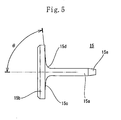
- the deflector 15 has a disk-shaped impact plate portion 15b provided at one end of the support bar 15a so that the deflector 14 is umbrella-shaped.
- the diameter of the support bar 15a is set to ⁇ 1.5mm
- the outer diameter of the impact plate portion 15b is set to ⁇ 11mm.
- a surface of the impact plate portion 15b at the side of the support bar 15a is set as an impact surface 15c against which the fluid impacts.
- An angle 8 between the impact surface 15c and the support bar 15a is formed in the range of an acute angle to a right angle. In this embodiment, the angle ⁇ is set to 85 degrees.
- a continuous portion 15d continuous with the impact plate portion 15b and an end of the support bar 15a is tapered and formed as a smooth curved surface from the periphery of the support bar 15a to the impact surface 15c of the impact plate portion 15b.
- the curvature of the continuous portion 15d is set in conformity to the angle ⁇ of the diameter-enlarged portion 12n of the jetting nozzle 12k in the nozzle tip 12. More specifically, the direction of the tangential line at the curved surface of the continuous portion 15d is set to be almost the same as that of the extended direction of the diameter-enlarged portion 12n.
- the other end 15e, of the support bar 15a, opposite to the one end thereof where the impact plate portion 15b is provided is tapered off to allow the other end 15e to be easily inserted into the fixed opening portion 14e of the adapter 14.
- the nozzle tip 12 is accommodated at the front side of the spatial portion 11f formed inside the nozzle body 11 with the ring-shaped packing 13 fitted on a front surface of the flange portion 12a to fit the peripheral portion 12h of the nozzle tip 12 at its front side in the aperture 11b of the nozzle body 11.
- the adapter 14 is accommodated in the spatial portion 11f of the nozzle body 11, and the inner fitting portion 14b of the adapter 14 at its front side is fitted on the outer fitting portion 12c disposed at the rear end of the nozzle tip 12 to contact the front-end surface 14c of the adapter 14 and the rear-end surface 12d of the nozzle tip 12 each other.
- the support bar 15a of the deflector 15 is inserted into the jetting nozzle 12k of the nozzle tip 12 and penetrated through the cavity portion 12e. Then the end 15e of the deflector 15 at its base side is inserted into the fixed opening portion 14e of the adapter 14 by press fit to thereby fix the deflector 15. Because the nozzle tip 12 and the adapter 14 are placed in position by the fitting between the outer fitting portion 12c and the inner fitting portion 14b, the nozzle tip 12 and the deflector 15 are also placed accurately in position.
- the support bar 15a is positioned at the center of the jetting nozzle 12k with a ring-shaped space formed between the support bar 15a and the periphery of the jetting nozzle 12k.
- the ring-shaped space serves as a flow path having a sufficient dimension in its width.
- the O-ring 16 is fitted on the ring groove 11d formed on the periphery of the nozzle body 11. Thereby the assembling of the nozzle 10 is completed.
- the nozzle 10 is assembled from a large number of component parts, as described above, a flow path having a complicated construction can be easily formed.
- the nozzle 10 is fastened to the fluid supply pipe (not shown) with the screw portion 11e of the nozzle body 11.
- a fluid T is fed into the nozzle 10 through the fluid supply pipe.
- a flow path 10a for the fluid T is formed in the gap between the inner surface of the peripheral wall of the spatial portion 11f of the nozzle body 11 and the periphery of the adapter 14 as well as the nozzle tip 12.
- the fluid T fed into the nozzle 10 flows to the front side of the nozzle 10 through the flow path 10a.
- the fluid T which has reached the peripheral wall portion 12f of the nozzle tip 12 flows into the swirl groove 12g.
- the fluid T has a swirl state.
- the fluid T in the swirl state passes through the swirl groove 12g, enters the cavity portion 12e which is the swirl chamber, and flows to the jetting nozzle 12k with the jetting nozzle 12k keeping the swirl state.
- the support bar 15a of the deflector 15 is present in the center of the cavity portion 12e, the fluid T keeping the swirl state progresses with the fluid T swirling spirally around the periphery of the support bar 15a serving as the nucleus of the swirl.
- the fluid T obtains a strong swirl force and is fine-grained.
- the fluid T which has reached the jetting nozzle 12k is discharged outward from the gap between the support bar 15a and the periphery of the jetting nozzle 12k.
- the fluid T is jetted in a direction a little outward from the direction along the periphery of the support bar 15a.
- the fluid T which has been jetted outward is deflected greatly in its direction along the curved surface of the continuous portion 15d continuous with the support bar 15a of the deflector 15 and the impact plate portion 15b.
- the deflected fluid T progresses in a substantially vertical direction along the impact surface 15c of the impact plate portion 15b and is jetted outward forcibly in a fine-grained state from the gap between the impact plate portion 15b and the front-end wall surface 11a of the nozzle body 11.
- the fluid T jetted outward in this manner is guided to the outside along the impact surface 15c smoothly, the fluid T is jetted in a uniform film state without generating turbulence in the jet pattern and jet direction of the fluid T fine-grained by the swirl, thus maintaining a stable jet pattern under the guide of the diameter-enlarged portion 12n of the projected jetting nozzle 12k and the curved surface of the continuous portion 15d of the deflector 15. Further because in this state, the fluid T impacts against the deflector 15 gently, the amount of the fluid T which splashes toward the jetting nozzle 12k is small. In addition, because the jetting nozzle 12k itself projects from the front end surface 12i of the nozzle tip 12, it never occurs that the fluid T attaches to the periphery of the jetting nozzle and prevents jetting of the fluid.
- a sufficient dimension is secured for portions, through which the fluid T passes, such as the flow path 10a, the swirl groove 12g, and the jetting nozzle 12k.
- portions, through which the fluid T passes such as the flow path 10a, the swirl groove 12g, and the jetting nozzle 12k.
- the nozzle 10 is capable of jetting fluids having a low viscosity and a high viscosity. Regarding the kind of the fluid, the nozzle 10 is capable of jetting a gas and a liquid. Further the nozzle 10 jets a fine-grained fluid at a wide angle. Thus as the application of the nozzle 10, the nozzle 10 can be utilized to form a protection coating film on the inner peripheral surface of a conduit which will be described later.
- the nozzle 10 provided with the deflector by altering the configuration of the deflector 15, it is possible to form various jetting angles and jetting patterns.
- the angle of the impact surfaces 25c, 25c' may be set to 60 degrees or 45 degrees to support bars 25a, 25a'.
- the angle of an impact surface 25c" may be set to 90 degrees.
- the angle of the impact surface of the deflector can be set to not less than 45 degrees to the support bar.
- the deflector In replacing the deflector, after the deflector is removed from the adapter 14, the deflector is fixed to the fixed opening portion 14e of the adapter 14 by press fit. Thereby the deflector can be easily mounted on the nozzle 10.
- the jetting angle of the nozzle is smaller than that of the nozzle having the deflector 15 mounted thereon.
- the deflectors 25, 25' can be used preferably in jetting the fluid in an oblique forward direction.
- the jetting angle of the nozzle 10 is wider than that of the nozzle 10 having the deflector 15 mounted thereon.
- a fluid is jetted approximately orthogonally to the axial direction of the nozzle 10.
- the angle of the diameter-enlarged portion 12n of the jetting nozzle 12k may be altered in conformity to the angle of the impact surface.
- the peripheral configuration of an impact plate portion 35b may be rectangularly formed.
- the jetting direction of the fluid is not uniform in all directions on the periphery of the nozzle but the jetting force at corners is low.
- a spray pattern of spreading the fluid radially in four directions is formed.
- the peripheral configuration of the impact plate portion 35b may be polygonal such as triangular, pentagonal, hexagonal, heptagonal, and octagonal.
- Fig. 9 shows a nozzle 50 of the second embodiment of the present invention.
- the distance L between an impact plate portion 55b of a deflector 55 and a front-end wall surface 51a of a nozzle body 51 can be adjusted so that a jetting mode can be adjusted.
- a ball plunger 55f urged by a spring is projected in the vicinity of an end portion 55e of a support bar 55a.
- a fixed opening portion 54e penetrating through the support bar 55a is formed deeper than the fixed opening portion 14e of the first embodiment, and first, second and third groove portions 54g, 54h, and 54i are concavely formed at certain intervals on an inner peripheral surface of the fixed opening portion 54e.
- each of the first through third groove portions 54g, 54h, and 54i is set to a dimension at which the ball plunger 55f of the support bar 55a can be fitted therein and locked thereto.
- the position of the second groove portion 54h is so set that with the support bar 55a inserted into the fixed opening portion 54e and with the ball plunger 55f fitted in the second groove portion 54h, the distance L between an impact surface 55c of the impact plate portion 55b and the front-end wall surface 51a is equal to the distance between the impact surface 55c and the front-end wall surface 11a of the nozzle 10 of the first embodiment.
- the first and third groove portions 54g, 54i are disposed by spacing them from the second groove portion 54h at an increase interval of the distance L or a decrease interval thereof.
- the portions of the deflector 55 and the adapter 54 other than the above-described portions, the nozzle body 51, a nozzle tip 52, a packing 53, and other portions have the same construction and configuration as those of the corresponding portion of the nozzle 10 of the first embodiment.
- the jetting mode of the nozzle 50 is similar to that of the nozzle 10 of the first embodiment in the state, shown in Fig. 9, in which the ball plunger 55f is fitted in and locked to the second groove portion 54h.
- the deflector 55 is moved from the state shown in Fig. 9 toward a side in which the distance L becomes long, and the ball plunger 55f is fitted in and locked to the first groove portion 54g so that as shown in Fig. 10 (A), the interval between the impact plate portion 55b and the front-end wall surface 51a has a distance L1.
- the fluid When a fluid is jetted from the jetting nozzle 52k in a swirl state by setting above-described interval to the distance L1, the fluid is jetted in a direction in which the fluid widens outward along the diameter-enlarged portion 52n of the jetting nozzle 52k. Because the distance L1 is longer than the distance L, the fluid widens outward to a higher extent than the fluid jetted from the nozzle 10 of the first embodiment and impacts against the impact surface 55c of the impact plate portion 55b with the fluid having a large thickness t1 in a liquid film.
- the deflector 55 When the jetting mode is altered to make the jetting speed high, the deflector 55 is moved from the state shown in Fig. 9 toward a side in which the distance L becomes short, and the ball plunger 55f is fitted in and locked to the third groove portion 54i so that as shown in Fig. 10 (B), the interval between the impact plate portion 55b and the front-end wall surface 51a has a distance L2.
- the distance L2 is shorter than the distance L in the first embodiment.
- the fluid impacts against the impact surface 55c with the fluid jetted from the jetting nozzle 52k not widening, namely, with a thickness t2 of the film of the fluid being smaller than that of the film of the fluid jetted from the nozzle 10 of the first embodiment.
- a jetting speed lost by the fluid in the impact is low.
- the nozzle 50 can be used widely by merely adjusting the position of the deflector 55.
- the adjustment of the position of the deflector 55 may be accomplished by preparing a large number of deflectors having different lengths to obtain the desired distance L by selectively using an appropriate deflector.
- a deflector having a support bar whose length can be increased and decreased may be used. Deflectors of modifications of the first embodiment is applicable to the nozzle 50.
- Fig. 11 shows a nozzle 80 of the third embodiment.
- An outer diameter R1 of an impact plate portion 85b of a deflector 85 is set smaller than an outer diameter R2 of a nozzle body 81 at its front-end wall surface 81a.
- the diameter of a continuous portion 85d continuous with the support bar 85a and the impact plate portion 85b and that of the impact surface 85c are enlarged from a position thereof opposed to a diameter-enlarged portion 82n of a jetting nozzle 82k.
- the angle of the continuous portion 85d and the impact surface 85c to the support bar 85a is set to 30 degrees.
- a peripheral surface 85g continuous with the impact surface 85c of the impact plate portion 85b is formed as a plane vertical to the support bar 85a.
- the portions of the deflector 85 other than the above-described portions has the same construction as that of the deflector of the nozzle 10 of the first embodiment.
- the nozzle body 81, a nozzle tip 82, a packing, and an adapter 84 have also the same construction and configuration as those of the corresponding portion of the nozzle 10 of the first embodiment.
- the fluid in the jetting of the fluid from the nozzle 80, the fluid is jetted from the jetting nozzle 82k along the impact surface 85c of the deflector 85 and the diameter-enlarged portion 82n with the fluid widening outward to a higher extent than the fluid jetted from the nozzle 10 of the first embodiment, changes the flow direction under the guide of the peripheral surface 85g of the impact plate portion 85b, and is jetted outward from the periphery of the impact plate portion 85b.
- the fluid In the range from the jetting nozzle 82k to the impact plate portion 85b, by the impact surface 85c inclining from the root of the jetting nozzle 82k and extending in a diameter-enlarged direction, the fluid is forcibly directed outward in its flow.
- a portion in which the flow stagnates is not generated on the periphery of the impact surface 85c, and very little fluid attaches to the impact surface 85c, even if jetting is continued.
- the impact plate portion 85b of the nozzle 80 of the third embodiment has a smaller diameter than the nozzle body 81. Therefore compared with the nozzle 10 of the first embodiment, the fluid is not affected by the impact plate portion 85b in an early time.
- the fluid is smoothly jetted outward through the gap between the impact plate portion 85b and a front-end wall 81a of the nozzle body 81, and a portion in which the flow of the fluid separates from the front-end wall 81a of the nozzle body 81 and does not flow forward is not generated, and little fluid attaches to the periphery of the impact plate portion 85b and the periphery of the tip of the nozzle body 81.
- the nozzle 80 guides the flow direction of the fluid mainly by the inclined impact surface 85c of the deflector 85, a projected portion 82j including the diameter-enlarged portion 82n therein may be eliminated from the jetting nozzle 82k.
- Modifications of the nozzle of the first embodiment is applicable to the nozzle 80. Further the nozzle 80 may be so constructed that the distance between the impact plate portion of the deflector and the front-end wall surface of can be adjusted to have various jetting modes.
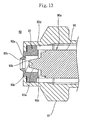
- Figs. 13 and 14 show a nozzle 90, of the fourth embodiment of the present invention, not provided with a deflector.
- the nozzle 90 has a nozzle body 91, a nozzle tip 92, and an adapter 93 each having a configuration similar to that of the first embodiment.
- the nozzle 90 is different from the first embodiment in that the deflector is not provided, the projection amount of a trapezoidal conic protruded portion 93a projecting from the tip of the adapter 93 is different from the protruded portion of the first embodiment, and the configuration of a concave portion 93c formed on a front-end surface 93b of the protruded portion 93a is different from the concave portion of the first embodiment.
- the trapezoidal conic protruded portion 93a projected into a cavity portion 92a, serving as a swirl chamber, formed inside the nozzle tip 92 has a larger projection amount than the protruded portion of the first embodiment to make the protruded portion 93a proximate to the jetting nozzle 92c and make the area of the front-end surface 93b of the protruded portion 93a equal to that of the jetting nozzle 92c, and make the axis of the protruded portion 93a coincident with the center of the jetting nozzle 92c.
- the concave portion 93c formed on the front-end surface of the protruded portion is formed conically.
- a ring-shaped flow path 90a is formed between the inner peripheral surface of the nozzle body 91 and the peripheral surface of the adapter 93.
- the flow path 90a communicates with the swirl chamber surrounded with the cavity portion 92a and the front-end wall of the adapter 93 through a swirl flow path 90b formed between a pair of curved swirl grooves 92d formed at opposed positions of the inner surface of the peripheral wall of the nozzle tip 92 and the front-end wall of the adapter 93.
- the trapezoidal conic protruded portion 93a is positioned at the center of an inflow side of the fluid spirally flowing into the swirl chamber from the swirl flow path 90b.
- the fluid spirally flowing into the swirl chamber is further swirled spirally along the peripheral surface of the trapezoidal conic protruded portion 93a and jetted from the jetting nozzle 92c formed at the tip of the swirl chamber at a wide angle to the periphery of the jetting nozzle 92c in the radial direction with the fluid being swirled.
- the fluid which has been flowed into the swirl chamber from the swirl flow path with the fluid being swirled is forcibly swirled along the peripheral surface of the trapezoidal conic protruded portion 93a. Further the protruded portion 93a is projected to a position proximate to the jetting nozzle 92c, and the outer diameter of the protruded portion is set almost equal to that of the jetting nozzle 92c. Therefore as shown in Fig. 14, the fluid can be jetted outward from the jetting nozzle 92c with the fluid being swirled spirally.
- the swirl flow is released to the air, it becomes a large swirl flow by a centrifugal force and is jetted radially at an angle wider than 90 degrees to the axis of the nozzle. Because an air core generated along the axis of the swirl flow can be accommodated in the conic concave portion 93c disposed on the front-end surface of the protruded portion, the air core can be held stably in the center of the jetting nozzle 92c. Thus by making the center of the swirl flow jetted from the jetting nozzle 92c always coincident with the center of the jetting nozzle 92c, the jetted fluid can be distributed uniformly in the radial direction.
- the nozzle not provided with the deflector is allowed to have performance almost equal to that of the deflector-provided nozzle of the first embodiment.
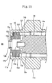
- Fig. 15 shows a nozzle 95 of a modification of the fourth embodiment.
- the nozzle of the modification is the same as the nozzle 10 of the first embodiment except that the nozzle of the modification is not provided with the deflector 15.
- the same component parts have the same reference numerals and description thereof is omitted herein.
- the present inventors have repeated experiments on the nozzle of the first embodiment by removing the deflector therefrom.
- the nozzle of the fourth embodiment provides wide-angle jetting similar to that obtained by the deflector-provided nozzle.
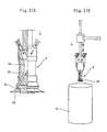
- Figs. 16 (A) and (B) show the fifth embodiment.
- Fig. 16 (A) shows a method of forming a protection coating film 120 on an inner peripheral surface 100a of a gas-flowing conduit 100 by using the nozzle 10 of the first embodiment.
- Fig. 16 (B) shows the case in which the nozzle 90 of the fourth embodiment is used.
- a rope 111 serving as a towing means is stretched to a jetting apparatus 110 on which the nozzle 10 or the nozzle 90 is mounted to allow a hollow part 100b of the gas pipe to move along an axis shown with the arrow.
- Guide rollers 113 are mounted on a guide plate 112 projected from the jetting apparatus 110 by urging the guide plate 112 with a coil spring 115. The guide rollers 113 slidably contacts the inner peripheral surface 100c of the gas conduit 100.
- Paint Q consisting of two-part hardening resin is jetted from the nozzle 10 or 90 mounted on the jetting apparatus 110.
- the side of the jetting apparatus 110 where the nozzle 10 (90) is located is set as the front end thereof.
- the jetting apparatus 110 is moved rearward as shown with the arrow.
- the paint Q is jetted from the nozzle 10 (90) disposed at the front end of the jetting apparatus 110 at a wide angle not less than 90 degrees (nearly 180 degrees in Fig. 16 (A)) to the axis of the nozzle. Therefore the paint Q is uniformly applied to the entire inner peripheral surface of the conduit 100.
- the paint is applied to the inner surface of the conduit by jetting the paint thereto by the deflector-provided nozzle 10.
- the paint is applied to the inner surface of the conduit by jetting the paint thereto by the deflector-unprovided nozzle 90.
- the paint is jetted thereto from the deflector-provided nozzle 10. Even if the inner peripheral surface of the conduit has irregularities, it is possible to form the coating layer 120 having a uniform thickness on the entire inner peripheral surface of the conduit including the surface of the irregularities.
- both the deflector-provided nozzle and the deflector-unprovided nozzle are capable of jetting the fluid at a wide angle to the entire periphery thereof. Therefore the nozzle can be used suitably when a coating film is formed on the inner peripheral surface of a conduit.
- a curved surface is formed continuously with the support bar of the deflector and the impact plate portion thereof. Therefore the fluid impacts the deflector gently and is guided outward smoothly to form a spray pattern having a stable configuration. Even when the jetting angle is not less than 150 degrees, a stable spray pattern can be maintained. Even if the fluid to be jetted has a high viscosity, the nozzle is also capable of maintaining a stable spray pattern. The nozzle is capable of jetting the fine-grained fluid uniformly at a wide angle.
- various jetting angles and spray patterns can be formed by preparing a large number of deflectors having various modes. Jetting can be accomplished in dependence on purpose.
- the distance between the impact plate portion of the deflector and the front-end wall is adjustable, various jetting modes can be realized.
- the outer diameter of the impact plate portion is set smaller than that of the nozzle body, it is possible to prevent an atomized fluid from attaching to the periphery of the front-end wall and the like and hence secure a stable successive jetting for a long lime.
Landscapes
- Nozzles (AREA)
- Application Of Or Painting With Fluid Materials (AREA)
- Spray Control Apparatus (AREA)
Abstract
A nozzle, comprising a nozzle body (11), a nozzle tip (12) stored in the nozzle body and a deflector (15) fitted to the tip side of the nozzle, the nozzle tip (12) further comprising a swirl groove (12g) in the rear end face (12d) thereof and a jetting nozzle (12k) projectedly provided thereon with the inner diameter thereof increased at the tip side, the deflector (15) further comprising a support bar (15a) and an impact plate part (15b) connected to each other through a continuous portion (15d) formed of a curved surface and smoothly continued to an impact surface (15c), wherein swirl fluid (T) is jetted from the jetting nozzle (12k) and deflected at the continuous portion (15d) to outwardly jet the fluid widely along the impact surface (15c). <IMAGE>
Description
The present invention relates to a nozzle and method
of jetting a fluid to an inner peripheral surface of a
conduit by means of the nozzle. More particularly, the
present invention relates to a nozzle that jets a fluid to
the periphery thereof in a wide range. In particular, the
nozzle is so constructed to realize wide-angle and uniform
jetting without dripping of the fluid, even though the
fluid has a high viscosity. The nozzle is used suitably
to apply paint to the inner peripheral surface of the
conduit.
Heretofore, as a nozzle capable of jetting a fluid
at an angle larger than 90 degrees with respect to the
axis of the nozzle, there are proposed a large number of
nozzles each having an umbrella-shaped deflector mounted
thereon.
In the nozzles provided with the deflector, a fluid
jetted from a jetting nozzle is impacted against an impact
plate portion of the deflector confronting the jetting
nozzle and is then jetted to the periphery of the jetting
nozzle along the impact plate portion.
Fig. 17 (A) shows the powder spray apparatus 1
disclosed in Japanese Patent Application Laid-Open No. 9-503957.
The powder spray apparatus 1 has the nozzle 2
having the deflector. The nozzle 2 has the conic first
deflector 2b provided on the conduit 2a for a fluid and
the second deflector 2d provided at the nozzle tip 2c.
The flow direction of the fluid flowing in the conduit 2a
is deflected outward by the first deflector 2a, deflected
widely by the second deflector 2d, and jetted to the
periphery of the nozzle 2.
The spray apparatus 3 disclosed in Japanese Patent
Application Laid-Open No. 62-97654 has the umbrella-shaped
deflector 3b at the tip of the nozzle portion 3a. In
Japanese Patent Application Laid-Open No. 10-244016, the
nozzle 4 having the deflector 4a is disclosed. In
addition, as shown in Fig. 18 (C), the nozzle 5 in which
the flow path 5c is formed on the periphery of the support
bar 5b of the deflector 5a is known.
Because the above-described nozzles having the
deflector respectively are capable of jetting a fluid at a
wide angle by the deflector, as shown in Fig. 17 (B), they
are frequently used to jet the fluid into a hollow body
such as a drum 6.
In the above-described conventional nozzles having
the deflector respectively, the fluid flowing inside the
nozzle is impacted against the impact plate portion of the
deflector without the flow of the fluid being made
turbulent. Thus it is difficult to fine-grain the fluid
to be jetted. Therefore the thickness of the jetted fluid
film is not uniform, and it is difficult to make a jetting
pattern stable. When a jetting angle is set widely, the
above phenomenon is frequently outstanding, and nonuniform
jetting is liable to occur. Further owing to splash of
the fluid which has impacted the deflector, the fluid
attaches to the periphery of the jetting nozzle and
dripping occurs, which prevents jetting of the fluid from
the jetting nozzle.
To overcome the difficulty in fine-graining the
fluid to be jetted, in a nozzle 5 shown in Fig. 18 (C),
the inner diameter of the flow path 5c is set small to
raise a fluid pressure. The nozzle having this
construction is liable to clog owing to the presence of a
foreign matter contained in the fluid flowing in the flow
path 5c. Thus much labor is required for maintenance.
Further when the fluid to be jetted is viscous, it is
impossible to make the jetting angle of the fluid large
because a pressure loss is great in the small-diameter
flow path 5c of the nozzle 5. More specifically, in the
nozzle 8 shown in Fig. 19 (A), the jetting angle can be
set to about 80 degrees when a jetting pressure is about
10 Mpa and when the fluid is water. But in the case of a
fluid having a high viscosity of 100 CP, the jetted fluid
drips from the nozzle, as shown in Fig. 19 (B). Thus a
jetting pattern cannot be secured.
The present invention has been made in view of the
above-described problems. Therefore it is a first object
of the present invention to provide a nozzle, having a
deflector, capable of fine-graining a fluid and jetting it
at a wide angle by properly sizing a necessary portion of
the nozzle to allow passage of a foreign matter. It is a
second object of the present invention to provide a nozzle
capable of jetting a fluid at a wide angle, even if the
deflector is not used.
It is a further object of the present invention to
provide a nozzle that is capable of jetting a fluid
uniformly at a wide angle, even if a fluid to be jetted
has a high viscosity and can be used suitably when paint
is jetted to the inner peripheral surface of a conduit.
The first invention provides a nozzle in which a
swirl chamber communicating with a jetting nozzle disposed
at a center of a jetting-side front-end wall is provided;
a support bar of a deflector is penetrated through the
jetting nozzle with a gap formed between the support bar
and a periphery of the jetting nozzle and is projected
inward; an impact plate portion of the deflector is
provided at an end portion of the support bar outward
projected; and the impact plate portion is disposed in
confrontation with the jetting-side front-end wall,
a fluid jetted in a swirl state from the swirl chamber through the jetting nozzle is impacted against the impact plate portion of the deflector to jet the fluid peripherally outwardly from a gap between the impact plate portion and the jetting-side front-end wall.
a fluid jetted in a swirl state from the swirl chamber through the jetting nozzle is impacted against the impact plate portion of the deflector to jet the fluid peripherally outwardly from a gap between the impact plate portion and the jetting-side front-end wall.
As described above, when the nozzle is provided with
the swirl chamber, the fluid in a swirl state impacts the
impact plate portion of the deflector. Thus the fluid
jetted outward on the periphery of the nozzle by
deflecting the fluid by the deflector can be fine-grained,
and the thickness of the film of the jetted fluid can be
made uniform. Further by swirling the flow of the fluid
jetted from the jetting nozzle, it is possible to make the
amount of the fluid jetted to the periphery of the jetting
nozzle uniform and easy to flow the fluid in conformity to
the angle of the impact surface of the impact plate
portion of the deflector. Thus the jetting pattern and
the jetting angle can be easily adjusted in conformity to
the configuration of the impact plate portion of the
deflector. Thereby it is possible to set the jetting
angle to a wide angle and a wide range.
By using the deflector having the above construction,
even if the fluid to be jetted has a high viscosity, it is
possible to secure wide and uniform spray owing to the
swirl flow of the fluid generated in the swirl chamber.
Further because a gap is formed between the support bar of
the deflector and the periphery of the jetting nozzle,
this portion secures a sufficient dimension large enough
for a foreign matter to pass therethrough. Thus it is
possible to prevent clogging of the foreign matter.
The jetting nozzle is formed on a nozzle tip
accommodated inside a nozzle body at a jetting side
thereof; a cavity portion is formed inside the nozzle tip
at a fluid inflow side thereof; and an adapter is fitted
on an end portion of the nozzle tip at the fluid inflow
side thereof in such a way as to close the cavity portion
to thereby function the cavity portion as the swirl
chamber;
a swirl flow path is formed on a peripheral portion of the nozzle tip to flow a fluid flowing along a flow path formed between an inner surface of a peripheral wall of the nozzle body and a periphery of the nozzle tip as well as the adapter into the swirl chamber as a swirl flow through the swirl flow path; and
an end portion, of the support bar of the deflector, disposed opposite to the impact plate portion is removably mounted on a front-end surface of the adapter.
By fixing the nozzle tip having the cavity portion
and the swirl flow path by means of the adapter inside the
nozzle body, it is possible to swirl the fluid
sufficiently and secure a sufficient dimension for the
swirl flow path. Thus it is possible to prevent clogging
of the foreign matter. Because the nozzle of the present
invention ensures a large dimension for foreign matter
passage portion, the nozzle is suitable for spraying a
small amount of a fluid.
As the swirl flow path, it is possible to form the
curved swirl groove communicating with the cavity portion
on the fitting surface of the peripheral wall of the
nozzle tip or form the curved swirl opening communicating
with the peripheral wall portion of the nozzle tip and the
cavity portion. The fluid may be swirled by using a
whirler. The nozzle is composed of a plurality of
component parts such as the nozzle body, the nozzle tip,
and the adapter, and the flow path is formed in the nozzle.
Thus the construction inside the nozzle may be complicated.
But by processing each component part, it is possible to
prevent an increase of the cost.
Because the support bar of the deflector is
penetrated through the jetting nozzle and is projected
inside the nozzle body, the support bar is positioned at
the center of the cavity portion (swirl chamber) and
serves as the axis or the nucleus of the swirl flow. Thus
the fluid can be forcibly swirled around the support bar.
Further the support bar of the deflector passes through
the cavity portion of the nozzle tip and is removably
fixed to the adapter. Therefore deflectors having various
configuration can be exchanged with each other. Thus
according to purpose of fluid jetting, the jetting angle
can be changed, and the jetting amount can be varied in
dependence on jetting directions. Because the adapter
fixing the support bar of the deflector is fitted on the
nozzle tip, positioning of the adapter and nozzle tip can
be accomplished accurately. Consequently the support bar
of the deflector can be accurately positioned at the
center of the jetting nozzle of the nozzle tip.
A front-end surface of the nozzle tip at which the
jetting nozzle is formed is fitted on an aperture formed
at a front-end portion of the nozzle body; and a
peripheral portion of the jetting nozzle of the nozzle tip
is projected from the front-end surface of the nozzle tip;
and an inner diameter of the jetting nozzle is enlarged
gradually toward a front end thereof. Because the
peripheral portion of the jetting nozzle of the nozzle tip
is projected from the front-end surface of the nozzle tip,
fluid can be eliminated from the periphery of the jetting
nozzle, and thus very little fluid attaches thereto.
Further the inner diameter of the jetting nozzle is
enlarged gradually toward the front end thereof. Thus a
large diameter can be secured to allow a foreign matter to
pass through the jetting nozzle without clogging. Since
the inner diameter of the jetting nozzle is enlarged
gradually toward the front end thereof, the flow direction
of the jetted fluid is widened outward. Thus enlargement
of the inner diameter of the jetting nozzle contributes to
stabilization of a spray pattern when the jetting angle is
set to a wide angle.
A continuous portion continuous with a support bar
of the deflector and an impact plate portion thereof is
tapered and formed as a curved surface in conformity to an
angle of the jetting nozzle. When the continuous portion
continuous with the support bar and the impact plate
portion is formed in this configuration, by combining the
continuous portion with the diameter-enlarged portion of
the jetting nozzle, it is possible to flow the fluid
smoothly along the tapered curved surface. Further it is
possible to prevent the fluid from strongly impacting the
continuous portion continuous with support bar and the
impact plate portion and thus prevent the jetting
direction of the fluid from becoming nonuniform and
scattering to the periphery of the jetting nozzle.
Thereby the impact of the fluid is gentle, and a reliable
spray pattern can be secured. Even when the jetting angle
is wide, it is possible to prevent the spray pattern from
being destroyed.
An impact surface, of the impact plate portion of
the deflector, disposed at a side of the jetting nozzle is
formed at an angle of not less than 25 nor more than 90
degrees to the support bar. By forming the impact surface
of the deflector at various angles, the nozzle can be used
for various uses. For example, when the fluid is desired
to be jetted vertically to a surface to which the fluid is
jetted, a deflector whose impact surface is at right
angles to its support bar should be used. Further by
inclining the impact surface at an angle in the above-described
range, it is possible to prevent scattering of
an atomized fluid, prevent a spray from attaching to the
support bar and the like, and secure a stable atomized
state in successive fluid jetting. Because the deflector
is removably fixed to the adapter, the deflector can be
exchanged suitably in dependence on purpose.
A distance between the impact plate portion of the
deflector and the jetting-side front-end wall can be
increasingly or decreasingly changed. When the distance
between the impact plate portion and the jetting-side
front-end wall is adjustable, the fluid impacts the impact
plate portion in different states. Thus various atomizing
modes are applicable in dependence on purpose. More
specifically, when the distance between the impact plate
portion and the jetting-side front-end wall is set long,
the fluid impacts the impact plate portion in a state in
which the fluid spreads along the configuration of the
jetting nozzle. Thus the thickness of the fluid film at
the impact surface of the impact plate portion is large,
and the jetting speed from the impact plate portion is low.
Consequently the particle diameter of the fluid is large.
On the other hand, when the distance between the
impact plate portion and the jetting-side front-end wall
is set short, the fluid impacts the impact plate portion
in a state in which the fluid does not spread much from
the jetting nozzle. Thus the thickness of the fluid film
at the impact surface is small, and the loss of the
jetting speed is small. Consequently the particle
diameter of the fluid is small. It is preferable to
adjust the distance between the impact plate portion and
the jetting-side front-end wall by mounting the support
bar of the deflector on the nozzle tip from a shallow
state to a deep state or exchanging one deflector whose
support bar is long with the other deflector whose support
bar is short or vice versa.
It is preferable that an outer diameter of the
impact plate portion of the deflector is set smaller than
an outer diameter of the jetting-side front-end wall.
When the peripheral dimension of the impact plate portion
is set smaller than the outer diameter of the nozzle body
disposed at the jetting side, in the peripheral portion of
the front-end wall, the impact plate portion is not
present in confrontation with the front-end wall.
Therefore when the fluid is jetted outward from the gap
between the impact plate portion and the front-end wall at
its jetting side, the fluid flows outward smoothly from
the impact plate portion. Consequently it is possible to
securely prevent an atomized fluid from attaching to the
periphery of the front-end wall and the like and hence
secure a stable spray state.
A periphery of the impact plate portion of the
deflector is formed circularly or polygonally. When the
impact plate portion having the above-described
configuration is used, it is possible to accomplish a
uniform spray and a nonuniform spray. For example, when
the fluid is desired to be sprayed uniformly, the
peripheral configuration of the impact plate portion
should be circular. When the fluid is is desired to be
sprayed nonuniformly to a specific direction, the impact
plate portion should be formed in a configuration having a
corner according to a jetting direction. As
configurations other than the above-described
configurations, the impact plate portion may be formed
elliptically or asymmetrically.
When the impact surface of the deflector is set to
various angles or the periphery of the impact plate
portion is formed in various configurations, the fluid
film is stable and the diameter of fine-grained particle
changes very little because the fluid which impacts the
deflector is in a swirl state. Therefore the nozzle of
the present invention is suitable for jetting the fluid
into the inside of a hollow body.
The second invention provides a nozzle capable of
jetting a fluid at a wide angle, although the deflector is
not mounted on the nozzle.
In the nozzle, a ring-shaped flow path is formed
along an inner surface of a peripheral wall of a nozzle
body; a swirl chamber communicating with a jetting nozzle
positioned at a center of an end of the nozzle body at a
jetting side thereof is formed; the swirl chamber and the
flow path are communicated with each other through a pair
of curved swirl flow paths formed at opposed positions; a
trapezoidal conic protruded portion is formed at a center
of the swirl chamber at an inflow side thereof; and a
fluid flowing swirlingly into the swirl chamber is further
swirled along a peripheral surface of the trapezoidal
conic protruded portion and jetted from the jetting nozzle
formed at a front end of the swirl chamber at a wide angle
with the fluid being swirled.
As a result of experiments made by the present
inventors, they have found that the fluid can be jetted at
an angle wider than 90 degrees with respect to the axis of
the deflector-unprovided nozzle by flowing the fluid into
the swirl chamber with the fluid swirling, accelerating
the swirling of the fluid inside the swirl chamber, and
jetting the fluid from the jetting nozzle by swirling it.
Owing to this finding, the second invention provides
the nozzle not provided with the deflector having the
construction described above.
That is, because the trapezoidal conic protruded
portion is present at the center of the swirl chamber, the
fluid which has flowed into the swirl chamber with the
fluid being swirled is forcibly swirled along the
peripheral surface of the trapezoidal conic protruded
portion. The flow of the fluid is accelerated in its
spiral swirling with a centrifugal force applied to the
fluid. Thus the fluid is jetted from the jetting nozzle
at a wide angle with the fluid swirling. Further the
swirling accelerates fine-graining of the fluid.
As described above, without mounting the deflector
on the nozzle tip with the deflector disposed outward from
the jetting nozzle of the nozzle and forcibly impacting
the fluid against the impact plate portion to thereby
convert the jetting direction to the direction outward
from the direction along the periphery of the support bar,
the fluid can be jetted from the jetting nozzle at an
angle wider than 90 degrees to the axis of the nozzle in
the direction outward from the direction along the
periphery of the support bar.
It is preferable that an axis of the trapezoidal
conic protruded portion is coincident with an axis of the
jetting nozzle; a front-end surface of the trapezoidal
conic protruded portion is disposed at a position
proximate and opposed to the jetting nozzle; and a size of
the jetting nozzle is set equally to a size of the front-end
surface of the protruded portion.
When the protruded portion is projected to the
position proximate to the trapezoidal conic protruded
portion, the fluid is forcibly swirled along the periphery
of the trapezoidal conic protruded portion until the fluid
is jetted from the jetting nozzle. Therefore the fluid
can be jetted from the jetting nozzle reliably in a swirl
flow.
When the area of the front-end surface of the
trapezoidal conic protruded portion is set almost equally
to that of the jetting nozzle, the swirl flow of the fluid
can be jetted in a large diameter from the jetting nozzle.
Thus it is possible to increase the jetting distance in
the peripheral direction.
It is preferable that an opening is concavely formed
at a center, of the front-end surface of the protruded
portion, positioned on an axis of an air core of a swirl
flow swirled in the swirl chamber and jetted from the
jetting nozzle; and the air core of the swirl flow is
stably held at the center of the jetting nozzle. It is
preferable that the opening concavely formed at the center
of the front-end surface of the protruded portion is
conically shaped to decrease the diameter of the opening
toward the inner end thereof. But the opening may be a
circular opening having an equal diameter.
By stably holding the air core of the swirl flow
separating from the trapezoidal conic peripheral surface
and swirlingly flowing to the jetting nozzle, it is
possible to make the jetting distance from the jetting
nozzle to the peripheral direction uniform and prevent
drips from being generated by a part of the fluid disposed
at the center of the swirl flow.
More specifically, similarly to the nozzle of the
first invention, a nozzle tip is accommodated inside the
nozzle body at a jetting side thereof; an adapter is
accommodated inside the nozzle body at an inflow side
thereof respect to the nozzle tip; the ring-shaped flow
path is formed between a peripheral surface of the adapter
and an inner peripheral surface of the nozzle body; and
the trapezoidal conic protruded portion is projected from
a front-end surface of the adapter at a jetting side
thereof;
a jetting nozzle is formed at a front end of the nozzle tip; a cavity portion, having a large area, continuous with the jetting nozzle is formed inside the nozzle tip; the swirl chamber is formed by closing a fluid inflow side of the cavity portion with a front-end surface of the adapter; and a swirl groove is formed at a position, of an inner surface of a peripheral wall of the nozzle tip, opposed to the front-end surface of the adapter.
a jetting nozzle is formed at a front end of the nozzle tip; a cavity portion, having a large area, continuous with the jetting nozzle is formed inside the nozzle tip; the swirl chamber is formed by closing a fluid inflow side of the cavity portion with a front-end surface of the adapter; and a swirl groove is formed at a position, of an inner surface of a peripheral wall of the nozzle tip, opposed to the front-end surface of the adapter.
A fluid to be supplied to the nozzle is paint having
a high viscosity of approximately 100 cp. The nozzle can
be most suitably used to line a conduit such as a gas pipe
by spraying two-part hardening resinous paint onto an
inner peripheral surface of the conduit.
The third invention provides a method of jetting a
fluid to an inner peripheral surface of a conduit by using
the deflector-provided nozzle of the first invention or
the deflector-unprovided nozzle of the second invention.
In the method of the third invention jetting a fluid
to an inner peripheral surface of a conduit by means of a
nozzle, the nozzle is moved inside the conduit at a
required speed and a fluid is jetted to an inner
peripheral surface of the conduit from the nozzle at an
angle not less than 90 degrees with respect to an axis of
the nozzle.
More specifically, a towing means such as a rope is
mounted on a jetting apparatus on which the nozzle is
mounted to allow a hollow part of the conduit to move
axially. A guide roller mounted on the tip of an arm
projected from the jetting apparatus is in contact with
the inner peripheral surface of the conduit. The fluid is
jetted from the nozzle at a wide angle while the jetting
apparatus is moving.
According to the above-described method, the fluid
can be almost uniformly jetted in all directions on the
periphery of the nozzle. Thus by jetting the fluid from
the nozzle with the nozzle being moved, the fluid can be
jetted entirely to the inner peripheral surface of the
conduit.
A fluid to be jetted from the nozzle consists of
paint consisting of a two-part hardening resin having a
high viscosity. The nozzle is capable of continuously
forming a coating film having a uniform thickness by
jetting the paint to the inner peripheral surface of the
conduit.
A nozzle according to an embodiment of the present
invention is described below with reference to the
drawings.
Figs. 1 through 6 show the first embodiment of the
present invention. A nozzle 10 includes a nozzle body 11,
a nozzle tip 12, a packing 13, an adapter 14, a deflector
15, and an O-ring 16.
The nozzle body 11 is approximately cylindrical in
its outer configuration, has a large aperture 11b on its
front-end wall surface 11a, and has a nut portion 11c
formed on its central peripheral portion. A ring groove
11d is concavely formed rearward from the nut portion 11c.
A screw portion 11e on which a fluid supply pipe (not
shown) is installed is formed on the rear periphery of the
nozzle body 11. A cylindrical spatial portion 11f
communicating with the aperture 11b is formed inside the
nozzle body 11.
As shown in Figs. 4 (A) and (B), the nozzle tip 12
is a short columnar member and has a flange portion 12a
formed at approximately the central portion of its
periphery. On an end portion 12b at the rear side of the
nozzle tip 12, a outer fitting portion 12c to be fitted on
the adapter 14 is formed except a peripheral wall of the
end portion 12b. A rear-end surface 12d is formed at the
inner side of the outer fitting portion 12c. A central
portion of the rear-end surface 12d is deeply concavely
formed to form a cavity portion 12e serving as a swirl
chamber. A curved swirl groove 12g communicating with a
peripheral wall portion 12f and a cavity portion 12e is
concavely formed as a swirl flow path at two opposed
positions on the rear-end surface 12d. As shown Fig. 4
(C), the bottom surface of the swirl groove 12g is
semicircular. In the swirl groove 12g of this embodiment,
its groove width is set to 0.6mm, its groove depth is set
to 0.5mm, and the radius R of its bottom surface is set to
0.3mm. That is, the swirl groove 12g secures dimensions
so that a fluid is capable of passing through the swirl
groove 12g without the swirl groove 12g being clogged,
even though an alien substance are mixed with the fluid.
The outer diameter of a peripheral portion 12h
disposed forward from the flange portion 12a of the nozzle
tip 12 is set to a dimension at which the peripheral
portion 12h can be fitted in the aperture 11b of the
front-end wall surface 11a of the nozzle body 11. A
trapezoidal conic projected portion 12j is formed at a
central portion of a front end surface 12i of the nozzle
tip 12. A jetting nozzle 12k communicating with the
cavity portion 12e formed inside the nozzle tip 12 is
formed at a central portion of the projected portion 12j.
A portion of the jetting nozzle 12k continuous with the
cavity portion 12e is set as a same-diameter portion 12m
having the same inner diameter. A portion of the jetting
nozzle 12k disposed in the projected portion 12j is set as
a diameter-enlarged portion 12n whose diameter increases
gradually toward its front end. In the jetting nozzle 12k
of this embodiment, the same-diameter portion 12m is set
to 2mm, and the angle α of the diameter-enlarged portion
12n is set to 60 degrees.
The adapter 14 to be fitted on the nozzle tip 12 at
its rear portion which is a fluid inflow side is columnar.
The outer diameter of a peripheral portion 14a of the
adapter 14 is set smaller than the inner diameter of the
spatial portion 11f of the nozzle body 11. The periphery
of the adapter 14 at its front side is stepped to form an
inner fitting portion 14b which fits on the nozzle tip 12.
A trapezoidal conic protruded portion 14d is formed at a
central portion of a front-end surface 14c. A fixed
opening portion 14e for a support bar 15a of the deflector
15 is concavely formed at the center of the protruded
portion 14d. As shown in Fig. 5, the deflector 15 has a
disk-shaped impact plate portion 15b provided at one end
of the support bar 15a so that the deflector 14 is
umbrella-shaped. In this embodiment, the diameter of the
support bar 15a is set to 1.5mm, and the outer diameter
of the impact plate portion 15b is set to 11mm. A
surface of the impact plate portion 15b at the side of the
support bar 15a is set as an impact surface 15c against
which the fluid impacts. An angle 8 between the impact
surface 15c and the support bar 15a is formed in the range
of an acute angle to a right angle. In this embodiment,
the angle is set to 85 degrees. A continuous portion
15d continuous with the impact plate portion 15b and an
end of the support bar 15a is tapered and formed as a
smooth curved surface from the periphery of the support
bar 15a to the impact surface 15c of the impact plate
portion 15b.
The curvature of the continuous portion 15d is set
in conformity to the angle α of the diameter-enlarged
portion 12n of the jetting nozzle 12k in the nozzle tip 12.
More specifically, the direction of the tangential line at
the curved surface of the continuous portion 15d is set to
be almost the same as that of the extended direction of
the diameter-enlarged portion 12n. The other end 15e, of
the support bar 15a, opposite to the one end thereof where
the impact plate portion 15b is provided is tapered off to
allow the other end 15e to be easily inserted into the
fixed opening portion 14e of the adapter 14.
In assembling the nozzle 10, as shown in Figs. 2 and
3, initially the nozzle tip 12 is accommodated at the
front side of the spatial portion 11f formed inside the
nozzle body 11 with the ring-shaped packing 13 fitted on a
front surface of the flange portion 12a to fit the
peripheral portion 12h of the nozzle tip 12 at its front
side in the aperture 11b of the nozzle body 11.
Thereafter the adapter 14 is accommodated in the spatial
portion 11f of the nozzle body 11, and the inner fitting
portion 14b of the adapter 14 at its front side is fitted
on the outer fitting portion 12c disposed at the rear end
of the nozzle tip 12 to contact the front-end surface 14c
of the adapter 14 and the rear-end surface 12d of the
nozzle tip 12 each other.
In the above-described state, the support bar 15a of
the deflector 15 is inserted into the jetting nozzle 12k
of the nozzle tip 12 and penetrated through the cavity
portion 12e. Then the end 15e of the deflector 15 at its
base side is inserted into the fixed opening portion 14e
of the adapter 14 by press fit to thereby fix the
deflector 15. Because the nozzle tip 12 and the adapter
14 are placed in position by the fitting between the outer
fitting portion 12c and the inner fitting portion 14b, the
nozzle tip 12 and the deflector 15 are also placed
accurately in position. The support bar 15a is positioned
at the center of the jetting nozzle 12k with a ring-shaped
space formed between the support bar 15a and the periphery
of the jetting nozzle 12k. In the jetting nozzle 12k, the
ring-shaped space serves as a flow path having a
sufficient dimension in its width. Finally the O-ring 16
is fitted on the ring groove 11d formed on the periphery
of the nozzle body 11. Thereby the assembling of the
nozzle 10 is completed. The nozzle 10 is assembled from a
large number of component parts, as described above, a
flow path having a complicated construction can be easily
formed.
Jetting of a fluid by the nozzle 10 assembled as
described above is described below with reference to Fig.
6.
The nozzle 10 is fastened to the fluid supply pipe
(not shown) with the screw portion 11e of the nozzle body
11. A fluid T is fed into the nozzle 10 through the fluid
supply pipe. In the nozzle 10, a flow path 10a for the
fluid T is formed in the gap between the inner surface of
the peripheral wall of the spatial portion 11f of the
nozzle body 11 and the periphery of the adapter 14 as well
as the nozzle tip 12. The fluid T fed into the nozzle 10
flows to the front side of the nozzle 10 through the flow
path 10a.
The fluid T which has reached the peripheral wall
portion 12f of the nozzle tip 12 flows into the swirl
groove 12g. As a result of passing of the fluid T through
the swirl groove 12g, the fluid T has a swirl state. The
fluid T in the swirl state passes through the swirl groove
12g, enters the cavity portion 12e which is the swirl
chamber, and flows to the jetting nozzle 12k with the
jetting nozzle 12k keeping the swirl state. Because the
support bar 15a of the deflector 15 is present in the
center of the cavity portion 12e, the fluid T keeping the
swirl state progresses with the fluid T swirling spirally
around the periphery of the support bar 15a serving as the
nucleus of the swirl. Thus the fluid T obtains a strong
swirl force and is fine-grained.
The fluid T which has reached the jetting nozzle 12k
is discharged outward from the gap between the support bar
15a and the periphery of the jetting nozzle 12k. In this
jetting, because the diameter-enlarged portion 12n is
formed at the front side of the jetting nozzle 12k, the
fluid T is jetted in a direction a little outward from the
direction along the periphery of the support bar 15a. The
fluid T which has been jetted outward is deflected greatly
in its direction along the curved surface of the
continuous portion 15d continuous with the support bar 15a
of the deflector 15 and the impact plate portion 15b. The
deflected fluid T progresses in a substantially vertical
direction along the impact surface 15c of the impact plate
portion 15b and is jetted outward forcibly in a fine-grained
state from the gap between the impact plate
portion 15b and the front-end wall surface 11a of the
nozzle body 11.
Because the fluid T jetted outward in this manner is
guided to the outside along the impact surface 15c
smoothly, the fluid T is jetted in a uniform film state
without generating turbulence in the jet pattern and jet
direction of the fluid T fine-grained by the swirl, thus
maintaining a stable jet pattern under the guide of the
diameter-enlarged portion 12n of the projected jetting
nozzle 12k and the curved surface of the continuous
portion 15d of the deflector 15. Further because in this
state, the fluid T impacts against the deflector 15 gently,
the amount of the fluid T which splashes toward the
jetting nozzle 12k is small. In addition, because the
jetting nozzle 12k itself projects from the front end
surface 12i of the nozzle tip 12, it never occurs that the
fluid T attaches to the periphery of the jetting nozzle
and prevents jetting of the fluid.
Further a sufficient dimension is secured for
portions, through which the fluid T passes, such as the
flow path 10a, the swirl groove 12g, and the jetting
nozzle 12k. Thus even if the fluid T contains foreign
matters therein, the fluid T is jetted continuously
without these fluid passage portions clogging. In
addition, because the fluid passage portions have a large
dimension respectively, it is possible to realize reliable
jetting of even a small amount of the fluid. Moreover,
even if the fluid has a high viscosity, it is possible to
flow the fluid smoothly by reducing a pressure loss and
the influence of a boundary layer and spray the fluid at a
wide angle and uniformly by guiding the swirl flow by the
deflector.
The nozzle 10 is capable of jetting fluids having a
low viscosity and a high viscosity. Regarding the kind of
the fluid, the nozzle 10 is capable of jetting a gas and a
liquid. Further the nozzle 10 jets a fine-grained fluid
at a wide angle. Thus as the application of the nozzle 10,
the nozzle 10 can be utilized to form a protection coating
film on the inner peripheral surface of a conduit which
will be described later.
In the nozzle 10 provided with the deflector, by
altering the configuration of the deflector 15, it is
possible to form various jetting angles and jetting
patterns.
For example, as can be seen from deflectors 25, 25'
shown in Figs. 7 (A), (B), by making the angle of impact
surfaces 25c, 25c' of disk-shaped impact plate portions
25b, 25b' smaller than 85 degrees which is the angle of
the deflector 15 of the first embodiment, the angle of the
impact surfaces 25c, 25c' may be set to 60 degrees or 45
degrees to support bars 25a, 25a'. As can be seen from a
deflector 25" shown in Figs. 7 (C), the angle of an impact
surface 25c" may be set to 90 degrees. The angle of the
impact surface of the deflector can be set to not less
than 45 degrees to the support bar.
In replacing the deflector, after the deflector is
removed from the adapter 14, the deflector is fixed to the
fixed opening portion 14e of the adapter 14 by press fit.
Thereby the deflector can be easily mounted on the nozzle
10. When the deflectors 25, 25' are used, the jetting
angle of the nozzle is smaller than that of the nozzle
having the deflector 15 mounted thereon. The deflectors
25, 25' can be used preferably in jetting the fluid in an
oblique forward direction. When the deflector 25" is
mounted on the nozzle 10, the jetting angle of the nozzle
10 is wider than that of the nozzle 10 having the
deflector 15 mounted thereon. Thus a fluid is jetted
approximately orthogonally to the axial direction of the
nozzle 10. In altering the angle of the impact surface of
the deflector, as described above, the angle of the
diameter-enlarged portion 12n of the jetting nozzle 12k
may be altered in conformity to the angle of the impact
surface.
In the configuration of the deflector, as can be
seen from a deflector 35 of Figs. 8 (A) and (B), the
peripheral configuration of an impact plate portion 35b
may be rectangularly formed. When the deflector is formed
in this way, the jetting direction of the fluid is not
uniform in all directions on the periphery of the nozzle
but the jetting force at corners is low. Thus a spray
pattern of spreading the fluid radially in four directions
is formed. In addition to the rectangular shape, the
peripheral configuration of the impact plate portion 35b
may be polygonal such as triangular, pentagonal, hexagonal,
heptagonal, and octagonal.
Fig. 9 shows a nozzle 50 of the second embodiment of
the present invention. The distance L between an impact
plate portion 55b of a deflector 55 and a front-end wall
surface 51a of a nozzle body 51 can be adjusted so that a
jetting mode can be adjusted. In the deflector 55, a ball
plunger 55f urged by a spring is projected in the vicinity
of an end portion 55e of a support bar 55a. In an adapter
54, a fixed opening portion 54e penetrating through the
support bar 55a is formed deeper than the fixed opening
portion 14e of the first embodiment, and first, second and
third groove portions 54g, 54h, and 54i are concavely
formed at certain intervals on an inner peripheral surface
of the fixed opening portion 54e.
The dimension of each of the first through third
groove portions 54g, 54h, and 54i is set to a dimension at
which the ball plunger 55f of the support bar 55a can be
fitted therein and locked thereto. The position of the
second groove portion 54h is so set that with the support
bar 55a inserted into the fixed opening portion 54e and
with the ball plunger 55f fitted in the second groove
portion 54h, the distance L between an impact surface 55c
of the impact plate portion 55b and the front-end wall
surface 51a is equal to the distance between the impact
surface 55c and the front-end wall surface 11a of the
nozzle 10 of the first embodiment. The first and third
groove portions 54g, 54i are disposed by spacing them from
the second groove portion 54h at an increase interval of
the distance L or a decrease interval thereof.
The portions of the deflector 55 and the adapter 54
other than the above-described portions, the nozzle body
51, a nozzle tip 52, a packing 53, and other portions have
the same construction and configuration as those of the
corresponding portion of the nozzle 10 of the first
embodiment.
The jetting mode of the nozzle 50 is similar to that
of the nozzle 10 of the first embodiment in the state,
shown in Fig. 9, in which the ball plunger 55f is fitted
in and locked to the second groove portion 54h. When the
jetting mode is altered to make the jetting speed low, the
deflector 55 is moved from the state shown in Fig. 9
toward a side in which the distance L becomes long, and
the ball plunger 55f is fitted in and locked to the first
groove portion 54g so that as shown in Fig. 10 (A), the
interval between the impact plate portion 55b and the
front-end wall surface 51a has a distance L1.
When a fluid is jetted from the jetting nozzle 52k
in a swirl state by setting above-described interval to
the distance L1, the fluid is jetted in a direction in
which the fluid widens outward along the diameter-enlarged
portion 52n of the jetting nozzle 52k. Because the
distance L1 is longer than the distance L, the fluid
widens outward to a higher extent than the fluid jetted
from the nozzle 10 of the first embodiment and impacts
against the impact surface 55c of the impact plate portion
55b with the fluid having a large thickness t1 in a liquid
film. Consequently a speed v1 of the fluid which is
jetted outward from the periphery of the impact plate
portion 55b is lower than that of the fluid jetted from
the nozzle 10 of the first embodiment, and the particle
diameter of the jetted fluid is larger than that of the
jetted fluid jetted from the nozzle 10 of the first
embodiment.
When the jetting mode is altered to make the jetting
speed high, the deflector 55 is moved from the state shown
in Fig. 9 toward a side in which the distance L becomes
short, and the ball plunger 55f is fitted in and locked to
the third groove portion 54i so that as shown in Fig. 10
(B), the interval between the impact plate portion 55b and
the front-end wall surface 51a has a distance L2.
When the fluid is jetted from the jetting nozzle 52k
in a swirl state by setting the above-described interval
to the distance L2, the distance L2 is shorter than the
distance L in the first embodiment. Thus the fluid
impacts against the impact surface 55c with the fluid
jetted from the jetting nozzle 52k not widening, namely,
with a thickness t2 of the film of the fluid being smaller
than that of the film of the fluid jetted from the nozzle
10 of the first embodiment. In the impact when the fluid
film is thin, a jetting speed lost by the fluid in the
impact is low. Consequently a speed v2 of the fluid which
is jetted outward from the periphery of the impact plate
portion 55b is higher than that of the fluid jetted from
the nozzle 10 of the first embodiment, and thus the
particle diameter of the jetted fluid is smaller than that
of the fluid jetted from the nozzle 10 of the first
embodiment.
As described above, by increasing or decreasing the
distance L, it is possible to increase and decrease the
jetting speed and the particle diameter of the fluid to be
jetted. Thus the nozzle 50 can be used widely by merely
adjusting the position of the deflector 55. In addition
to fitting the ball plunger in the groove portion and
locking the ball plunger thereto, the adjustment of the
position of the deflector 55 may be accomplished by
preparing a large number of deflectors having different
lengths to obtain the desired distance L by selectively
using an appropriate deflector. In addition, a deflector
having a support bar whose length can be increased and
decreased may be used. Deflectors of modifications of the
first embodiment is applicable to the nozzle 50.
Fig. 11 shows a nozzle 80 of the third embodiment.
An outer diameter R1 of an impact plate portion 85b of a
deflector 85 is set smaller than an outer diameter R2 of a
nozzle body 81 at its front-end wall surface 81a. The
diameter of a continuous portion 85d continuous with the
support bar 85a and the impact plate portion 85b and that
of the impact surface 85c are enlarged from a position
thereof opposed to a diameter-enlarged portion 82n of a
jetting nozzle 82k. The angle of the continuous portion
85d and the impact surface 85c to the support bar 85a is
set to 30 degrees. A peripheral surface 85g continuous
with the impact surface 85c of the impact plate portion
85b is formed as a plane vertical to the support bar 85a.
The portions of the deflector 85 other than the
above-described portions has the same construction as that
of the deflector of the nozzle 10 of the first embodiment.
The nozzle body 81, a nozzle tip 82, a packing, and an
adapter 84 have also the same construction and
configuration as those of the corresponding portion of the
nozzle 10 of the first embodiment.
As shown in Fig. 12, in the jetting of the fluid
from the nozzle 80, the fluid is jetted from the jetting
nozzle 82k along the impact surface 85c of the deflector
85 and the diameter-enlarged portion 82n with the fluid
widening outward to a higher extent than the fluid jetted
from the nozzle 10 of the first embodiment, changes the
flow direction under the guide of the peripheral surface
85g of the impact plate portion 85b, and is jetted outward
from the periphery of the impact plate portion 85b. In
the range from the jetting nozzle 82k to the impact plate
portion 85b, by the impact surface 85c inclining from the
root of the jetting nozzle 82k and extending in a
diameter-enlarged direction, the fluid is forcibly
directed outward in its flow. Thus a portion in which the
flow stagnates is not generated on the periphery of the
impact surface 85c, and very little fluid attaches to the
impact surface 85c, even if jetting is continued.
Once the fluid is jetted outward from the impact
plate portion 85b, the fluid is not affected by the impact
plate portion 85b. The impact plate portion 85b of the
nozzle 80 of the third embodiment has a smaller diameter
than the nozzle body 81. Therefore compared with the
nozzle 10 of the first embodiment, the fluid is not
affected by the impact plate portion 85b in an early time.
Therefore the fluid is smoothly jetted outward through the
gap between the impact plate portion 85b and a front-end
wall 81a of the nozzle body 81, and a portion in which the
flow of the fluid separates from the front-end wall 81a of
the nozzle body 81 and does not flow forward is not
generated, and little fluid attaches to the periphery of
the impact plate portion 85b and the periphery of the tip
of the nozzle body 81.
Even if the fluid is jetted continuously, a portion
to which the fluid attaches is not generated. Thus stable
jetting can be ensured for a long time. Because the
nozzle 80 guides the flow direction of the fluid mainly by
the inclined impact surface 85c of the deflector 85, a
projected portion 82j including the diameter-enlarged
portion 82n therein may be eliminated from the jetting
nozzle 82k. Modifications of the nozzle of the first
embodiment is applicable to the nozzle 80. Further the
nozzle 80 may be so constructed that the distance between
the impact plate portion of the deflector and the front-end
wall surface of can be adjusted to have various
jetting modes.
Figs. 13 and 14 show a nozzle 90, of the fourth
embodiment of the present invention, not provided with a
deflector.
The nozzle 90 has a nozzle body 91, a nozzle tip 92,
and an adapter 93 each having a configuration similar to
that of the first embodiment. The nozzle 90 is different
from the first embodiment in that the deflector is not
provided, the projection amount of a trapezoidal conic
protruded portion 93a projecting from the tip of the
adapter 93 is different from the protruded portion of the
first embodiment, and the configuration of a concave
portion 93c formed on a front-end surface 93b of the
protruded portion 93a is different from the concave
portion of the first embodiment.
The trapezoidal conic protruded portion 93a
projected into a cavity portion 92a, serving as a swirl
chamber, formed inside the nozzle tip 92 has a larger
projection amount than the protruded portion of the first
embodiment to make the protruded portion 93a proximate to
the jetting nozzle 92c and make the area of the front-end
surface 93b of the protruded portion 93a equal to that of
the jetting nozzle 92c, and make the axis of the protruded
portion 93a coincident with the center of the jetting
nozzle 92c.
The concave portion 93c formed on the front-end
surface of the protruded portion is formed conically.
In the nozzle 90, similarly to the nozzle of the
first embodiment, a ring-shaped flow path 90a is formed
between the inner peripheral surface of the nozzle body 91
and the peripheral surface of the adapter 93. The flow
path 90a communicates with the swirl chamber surrounded
with the cavity portion 92a and the front-end wall of the
adapter 93 through a swirl flow path 90b formed between a
pair of curved swirl grooves 92d formed at opposed
positions of the inner surface of the peripheral wall of
the nozzle tip 92 and the front-end wall of the adapter 93.
The trapezoidal conic protruded portion 93a is positioned
at the center of an inflow side of the fluid spirally
flowing into the swirl chamber from the swirl flow path
90b. The fluid spirally flowing into the swirl chamber is
further swirled spirally along the peripheral surface of
the trapezoidal conic protruded portion 93a and jetted
from the jetting nozzle 92c formed at the tip of the swirl
chamber at a wide angle to the periphery of the jetting
nozzle 92c in the radial direction with the fluid being
swirled.
Because other constructions are similar to those of
the first embodiment, description thereof is omitted
herein.
In the nozzle 90 not provided with the deflector,
the fluid which has been flowed into the swirl chamber
from the swirl flow path with the fluid being swirled is
forcibly swirled along the peripheral surface of the
trapezoidal conic protruded portion 93a. Further the
protruded portion 93a is projected to a position proximate
to the jetting nozzle 92c, and the outer diameter of the
protruded portion is set almost equal to that of the
jetting nozzle 92c. Therefore as shown in Fig. 14, the
fluid can be jetted outward from the jetting nozzle 92c
with the fluid being swirled spirally. Because the swirl
flow is released to the air, it becomes a large swirl flow
by a centrifugal force and is jetted radially at an angle
wider than 90 degrees to the axis of the nozzle. Because
an air core generated along the axis of the swirl flow can
be accommodated in the conic concave portion 93c disposed
on the front-end surface of the protruded portion, the air
core can be held stably in the center of the jetting
nozzle 92c. Thus by making the center of the swirl flow
jetted from the jetting nozzle 92c always coincident with
the center of the jetting nozzle 92c, the jetted fluid can
be distributed uniformly in the radial direction.
Further, by swirling the fluid along the periphery
of the trapezoidal conic protruded portion 93a, it is
possible to fine-grain the fluid. Even the nozzle not
provided with the deflector is allowed to have performance
almost equal to that of the deflector-provided nozzle of
the first embodiment.
Fig. 15 shows a nozzle 95 of a modification of the
fourth embodiment. The nozzle of the modification is the
same as the nozzle 10 of the first embodiment except that
the nozzle of the modification is not provided with the
deflector 15. Thus the same component parts have the same
reference numerals and description thereof is omitted
herein.
The present inventors have repeated experiments on
the nozzle of the first embodiment by removing the
deflector therefrom. In the experiments, by using a
viscous fluid at a low pressure as the fluid to be jetted,
the nozzle of the fourth embodiment provides wide-angle
jetting similar to that obtained by the deflector-provided
nozzle.
Figs. 16 (A) and (B) show the fifth embodiment. Fig.
16 (A) shows a method of forming a protection coating film
120 on an inner peripheral surface 100a of a gas-flowing
conduit 100 by using the nozzle 10 of the first embodiment.
Fig. 16 (B) shows the case in which the nozzle 90 of the
fourth embodiment is used.
A rope 111 serving as a towing means is stretched to
a jetting apparatus 110 on which the nozzle 10 or the
nozzle 90 is mounted to allow a hollow part 100b of the
gas pipe to move along an axis shown with the arrow.
Guide rollers 113 are mounted on a guide plate 112
projected from the jetting apparatus 110 by urging the
guide plate 112 with a coil spring 115. The guide rollers
113 slidably contacts the inner peripheral surface 100c of
the gas conduit 100.
Paint Q consisting of two-part hardening resin is
jetted from the nozzle 10 or 90 mounted on the jetting
apparatus 110.
Let is be supposed that the side of the jetting
apparatus 110 where the nozzle 10 (90) is located is set
as the front end thereof. The jetting apparatus 110 is
moved rearward as shown with the arrow. The paint Q is
jetted from the nozzle 10 (90) disposed at the front end
of the jetting apparatus 110 at a wide angle not less than
90 degrees (nearly 180 degrees in Fig. 16 (A)) to the axis
of the nozzle. Therefore the paint Q is uniformly applied
to the entire inner peripheral surface of the conduit 100.
As a first application, the paint is applied to the
inner surface of the conduit by jetting the paint thereto
by the deflector-provided nozzle 10. As a second
application, the paint is applied to the inner surface of
the conduit by jetting the paint thereto by the deflector-unprovided
nozzle 90. Finally as a third application, the
paint is jetted thereto from the deflector-provided nozzle
10. Even if the inner peripheral surface of the conduit
has irregularities, it is possible to form the coating
layer 120 having a uniform thickness on the entire inner
peripheral surface of the conduit including the surface of
the irregularities.
As apparent from the foregoing description,
according to the present invention, both the deflector-provided
nozzle and the deflector-unprovided nozzle are
capable of jetting the fluid at a wide angle to the entire
periphery thereof. Therefore the nozzle can be used
suitably when a coating film is formed on the inner
peripheral surface of a conduit. In the deflector-provided
nozzle, a curved surface is formed continuously
with the support bar of the deflector and the impact plate
portion thereof. Therefore the fluid impacts the
deflector gently and is guided outward smoothly to form a
spray pattern having a stable configuration. Even when
the jetting angle is not less than 150 degrees, a stable
spray pattern can be maintained. Even if the fluid to be
jetted has a high viscosity, the nozzle is also capable of
maintaining a stable spray pattern. The nozzle is
capable of jetting the fine-grained fluid uniformly at a
wide angle.
In addition, because the deflector can be easily
removably mounted on the nozzle, various jetting angles
and spray patterns can be formed by preparing a large
number of deflectors having various modes. Jetting can be
accomplished in dependence on purpose. When the distance
between the impact plate portion of the deflector and the
front-end wall is adjustable, various jetting modes can be
realized. When the outer diameter of the impact plate
portion is set smaller than that of the nozzle body, it is
possible to prevent an atomized fluid from attaching to
the periphery of the front-end wall and the like and hence
secure a stable successive jetting for a long lime.
Furthermore in both the deflector-provided nozzle
and the deflector-unprovided nozzle, a sufficient
dimension is secured for the flow path inside the nozzle.
Thus a foreign matter contained in the fluid is capable of
passing through the flow path without clogging. Thereby
labor required to maintain the nozzle can be reduced.
Claims (16)
- A nozzle in which a swirl chamber communicating with a jetting nozzle disposed at a center of a jetting-side front-end wall is provided; a support bar of a deflector is penetrated through said jetting nozzle with a gap formed between said support bar and a periphery of said jetting nozzle and is projected inward; an impact plate portion of said deflector is provided at an end portion of said support bar outward projected; and said impact plate portion is disposed in confrontation with said jetting-side front-end wall,
a fluid jetted in a swirl state from said swirl chamber through said jetting nozzle is impacted against said impact plate portion of said deflector to jet said fluid peripherally outwardly from a gap between said impact plate portion and said jetting-side front-end wall. - The nozzle according to claim 1, wherein said jetting nozzle is formed on a nozzle tip accommodated inside a nozzle body at a jetting side thereof; a cavity portion is formed inside said nozzle tip at a fluid inflow side thereof; and an adapter is fitted on an end portion of said nozzle tip at said fluid inflow side thereof in such a way as to close said cavity portion to thereby function said cavity portion as said swirl chamber;
a swirl flow path is formed on a peripheral portion of said nozzle tip to flow a fluid flowing along a flow path formed between an inner surface of a peripheral wall of said nozzle body and a periphery of said nozzle tip as well as said adapter into said swirl chamber as a swirl flow through said swirl flow path; and
an end portion, of said support bar of said deflector, disposed opposite to said impact plate portion is removably mounted on a front-end surface of said adapter. - The nozzle according to claim 2, wherein a front-end surface of said nozzle tip at which said jetting nozzle is formed is fitted on an aperture formed at a front-end portion of said nozzle body; and a peripheral portion of said jetting nozzle of said nozzle tip is projected from said front-end surface of said nozzle tip; and an inner diameter of said jetting nozzle is enlarged gradually toward a front end thereof.
- The nozzle according to claim 3, wherein a continuous portion continuous with a support bar of said deflector and an impact plate portion thereof is tapered and formed as a curved surface in conformity to an angle of said jetting nozzle.
- The nozzle according to any one of claims 1 through 4, wherein an impact surface, of said impact plate portion of said deflector, disposed at a side of said jetting nozzle is formed at an angle of not less than 25 nor more than 90 degrees to said support bar.
- The nozzle according to any one of claims 1 through 5, wherein a distance between said impact plate portion of said deflector and said jetting-side front-end wall can be increasingly or decreasingly changed.
- The nozzle according to any one of claims 1 through 6, wherein an outer diameter of said impact plate portion of said deflector is set smaller than an outer diameter of said jetting-side front-end wall.
- The nozzle according to any one of claims 1 through 7, wherein a periphery of said impact plate portion of said deflector is formed circularly or polygonally.
- A nozzle in which a ring-shaped flow path is formed along an inner surface of a peripheral wall of a nozzle body; a swirl chamber communicating with a jetting nozzle positioned at a center of an end of said nozzle body at a jetting side thereof is formed; said swirl chamber and said flow path are communicated with each other through a pair of curved swirl flow paths formed at opposed positions; a trapezoidal conic protruded portion is formed at a center of said swirl chamber at an inflow side thereof; and a fluid flowing swirlingly into said swirl chamber is further swirled along a peripheral surface of said trapezoidal conic protruded portion and jetted from said jetting nozzle formed at a front end of said swirl chamber at a wide angle with said fluid being swirled.
- The nozzle according to claim 9, wherein an axis of said trapezoidal conic protruded portion is coincident with an axis of said jetting nozzle; a front-end surface of said trapezoidal conic protruded portion is disposed at a position proximate and opposed to said jetting nozzle; and a size of said jetting nozzle is set equally to a size of said front-end surface of said protruded portion.
- The nozzle according to claim 10, wherein an opening is concavely formed at a center, of said front-end surface of said protruded portion, positioned on an axis of an air core of a swirl flow swirled in said swirl chamber and jetted from said jetting nozzle; and said air core of said swirl flow is stably held at said center of said jetting nozzle.
- The nozzle according to claim 11, wherein said opening concavely formed at said center of said front-end surface of said protruded portion is conically shaped to decrease a diameter of said opening toward an inner end thereof.
- The nozzle according to any one of claims 9 through 12, wherein a nozzle tip is accommodated inside said nozzle body at a jetting side thereof; an adapter is accommodated inside said nozzle body at an inflow side thereof with respect to said nozzle tip; said ring-shaped flow path is formed between a peripheral surface of said adapter and an inner peripheral surface of said nozzle body; and said trapezoidal conic protruded portion is projected from a front-end surface of said adapter at a jetting side thereof;
the jetting nozzle is formed at a front end of said nozzle tip; a cavity portion, having a large area, continuous with said jetting nozzle is formed inside said nozzle tip; said swirl chamber is formed by closing a fluid inflow side of said cavity portion with a front-end surface of said adapter; and a swirl groove is formed at a position, of an inner surface of a peripheral wall of said nozzle tip, opposed to said front-end surface of said adapter. - The nozzle according to any one of claims 1 through 13, wherein a fluid to be supplied to said nozzle is paint having a high viscosity; and said nozzle is used to line a conduit such as a gas pipe by spraying said paint to an inner peripheral surface of said conduit.
- A method of jetting a fluid to an inner peripheral surface of a conduit by means of a nozzle according to any one of claims 1 through 13 by moving said nozzle inside said conduit at a required speed and jetting a fluid to an inner peripheral surface of said conduit from said nozzle at an angle not less than 90 degrees with respect to an axis of said nozzle.
- A method of jetting a fluid to an inner peripheral surface of a conduit by means of a nozzle, wherein a fluid to be jetted from said nozzle consists of paint having a high viscosity; and said paint is jetted to said inner peripheral surface of said conduit to form a coating film thereon.
Applications Claiming Priority (5)
| Application Number | Priority Date | Filing Date | Title |
|---|---|---|---|
| JP2001258807 | 2001-08-28 | ||
| JP2001258807 | 2001-08-28 | ||
| JP2002240920 | 2002-08-21 | ||
| JP2002240920A JP3801967B2 (en) | 2001-08-28 | 2002-08-21 | NOZZLE AND METHOD OF INJECTING FLUID TO INTERNAL PERIPHERAL SURFACE BY NOZZLE |
| PCT/JP2002/008584 WO2003020430A1 (en) | 2001-08-28 | 2002-08-26 | Nozzle and method of jetting fluid onto inner peripheral surface of conduit by the nozzle |
Publications (1)
| Publication Number | Publication Date |
|---|---|
| EP1421996A1 true EP1421996A1 (en) | 2004-05-26 |
Family
ID=26621168
Family Applications (1)
| Application Number | Title | Priority Date | Filing Date |
|---|---|---|---|
| EP02765351A Withdrawn EP1421996A1 (en) | 2001-08-28 | 2002-08-26 | Nozzle and method of jetting fluid onto inner peripheral surface of conduit by the nozzle |
Country Status (5)
| Country | Link |
|---|---|
| US (1) | US20040227016A1 (en) |
| EP (1) | EP1421996A1 (en) |
| JP (1) | JP3801967B2 (en) |
| CA (1) | CA2458822A1 (en) |
| WO (1) | WO2003020430A1 (en) |
Cited By (13)
| Publication number | Priority date | Publication date | Assignee | Title |
|---|---|---|---|---|
| WO2009060240A1 (en) * | 2007-11-09 | 2009-05-14 | Pursuit Dynamics Plc | An improved mist generating apparatus |
| US8193395B2 (en) | 2007-05-02 | 2012-06-05 | Pursuit Dynamics Plc | Biomass treatment process and system |
| US8419378B2 (en) | 2004-07-29 | 2013-04-16 | Pursuit Dynamics Plc | Jet pump |
| RU2486965C2 (en) * | 2011-04-01 | 2013-07-10 | Николай Васильевич Барсуков | Swirling nozzle |
| US8789769B2 (en) | 2006-09-15 | 2014-07-29 | Tyco Fire & Security Gmbh | Mist generating apparatus and method |
| US9004375B2 (en) | 2004-02-26 | 2015-04-14 | Tyco Fire & Security Gmbh | Method and apparatus for generating a mist |
| US9010663B2 (en) | 2004-02-26 | 2015-04-21 | Tyco Fire & Security Gmbh | Method and apparatus for generating a mist |
| RU2561107C1 (en) * | 2014-10-08 | 2015-08-20 | Николай Васильевич Барсуков | Jet-vortex atomiser with ejecting flame |
| RU184936U1 (en) * | 2018-08-03 | 2018-11-14 | Федеральное государственное бюджетное образовательное учреждение высшего образования "Амурский государственный университет" | Centrifugal nozzle with nozzle |
| US10507480B2 (en) | 2004-02-26 | 2019-12-17 | Tyco Fire Products Lp | Method and apparatus for generating a mist |
| RU2725408C1 (en) * | 2019-12-26 | 2020-07-02 | Общество с ограниченной ответственностью Центр прикладных исследований "Пульсар" - участник Проекта "Сколково" | Low-pressure vacuum-vortex nozzle with ejecting flame |
| EP3053654B1 (en) * | 2015-02-03 | 2021-04-07 | Xiamen Solex High-Tech Industries Co., Ltd. | An outlet device with hollow water curtain function |
| RU221677U1 (en) * | 2023-03-24 | 2023-11-16 | Алексей Сергеевич Аничкин | INJECTION NOZZLE |
Families Citing this family (24)
| Publication number | Priority date | Publication date | Assignee | Title |
|---|---|---|---|---|
| JP4580198B2 (en) * | 2004-08-24 | 2010-11-10 | エア・ウォーター防災株式会社 | Liquid jet nozzle |
| US7601304B1 (en) * | 2004-09-09 | 2009-10-13 | Uop Llc | Distribution apparatus for contact of hydrocarbon compounds with particles |
| JP4562076B2 (en) * | 2004-11-01 | 2010-10-13 | 日本曹達株式会社 | Metal sodium spraying apparatus and method |
| CA2607864C (en) * | 2005-05-13 | 2013-05-28 | Masco Corporation Of Indiana | Power sprayer |
| US11267003B2 (en) | 2005-05-13 | 2022-03-08 | Delta Faucet Company | Power sprayer |
| WO2007000330A2 (en) * | 2005-06-29 | 2007-01-04 | Boehringer Ingelheim International Gmbh | Method and device for atomising liquid |
| KR100829162B1 (en) * | 2006-12-04 | 2008-05-13 | 김희곤 | Apparatus and method for coating inner circumferential surface of pipe |
| DE102007017513A1 (en) * | 2007-04-13 | 2008-10-16 | Bayerische Motoren Werke Aktiengesellschaft | Device for coating components |
| KR101242238B1 (en) | 2007-07-16 | 2013-03-11 | 현대자동차주식회사 | spray apparatus for hole part exclusive |
| JP5191239B2 (en) * | 2008-01-07 | 2013-05-08 | 旭サナック株式会社 | Spraying equipment |
| JP5189417B2 (en) * | 2008-06-25 | 2013-04-24 | 三ツ星ベルト株式会社 | Electrostatic flocking pile diffusion nozzle |
| US8695898B2 (en) * | 2008-12-10 | 2014-04-15 | Masco Corporation Of Indiana | Spout including a stream straightener |
| WO2011097039A1 (en) * | 2010-02-08 | 2011-08-11 | Par Aide Products Co. | Method and system to whiten a golf hole |
| US8372354B2 (en) * | 2010-07-19 | 2013-02-12 | Chevron U.S.A. Inc. | Multiphase contact and distribution apparatus for hydroprocessing |
| FR2971768B1 (en) * | 2011-02-18 | 2013-03-22 | Valois Sas | HEAD OF DISTRIBUTION OF FLUID PRODUCT. |
| JP5922363B2 (en) * | 2011-08-04 | 2016-05-24 | ホーチキ株式会社 | Liquid spray device and charging spray head |
| JP5956760B2 (en) * | 2012-02-03 | 2016-07-27 | 株式会社ブリヂストン | Cleaning nozzle |
| FR3008899B1 (en) * | 2013-07-25 | 2017-04-21 | Arkema France | METHOD AND SYSTEM FOR DISPENSING A LIQUID IN CAPACITIES FOR THE PREPARATION OF (METH) ACRYLIC MONOMERS |
| KR101673700B1 (en) * | 2013-12-24 | 2016-11-07 | 가부시키가이샤 니프코 | Spray nozzle |
| EP3240435B1 (en) * | 2014-12-31 | 2018-10-03 | Nestec S.A. | Method of controlling the spray droplet size of a spray nozzle apparatus for spray-drying applications, spray drying apparatus and nozzle therefore |
| KR102037638B1 (en) * | 2019-06-27 | 2019-10-28 | 고일영 | Stirrer with function of removing suspension and bubbles equipped with buoyant portion |
| JP7008378B1 (en) * | 2021-05-24 | 2022-02-15 | 修 小川 | Insert for ejection nozzle tube |
| CN115301431B (en) * | 2022-09-14 | 2023-08-15 | 华能国际电力股份有限公司 | High-viscosity slurry atomizing nozzle for inner wall of boiler tube of thermal power unit |
| US20240182178A1 (en) * | 2022-12-01 | 2024-06-06 | Pratt & Whitney Canada Corp. | Aircraft engine with exhaust having removable deflector |
Family Cites Families (8)
| Publication number | Priority date | Publication date | Assignee | Title |
|---|---|---|---|---|
| JPS58107158U (en) * | 1982-01-08 | 1983-07-21 | 鬼頭工業株式会社 | cleaning nozzle |
| JPS59109267A (en) * | 1982-12-15 | 1984-06-23 | デブレツエニ・メゼ−ゲプジヤ−ルト−・エ−シユ・ソルガ−ルタト−・ヴア−ララト | Circulating sprinkling head |
| JPH029881Y2 (en) * | 1985-09-24 | 1990-03-12 | ||
| US4819879A (en) * | 1985-10-25 | 1989-04-11 | Nordson Corporation | Particle spray gun |
| JPS63130163U (en) * | 1987-02-13 | 1988-08-25 | ||
| JPH0632812Y2 (en) * | 1989-06-21 | 1994-08-31 | 鬼頭工業株式会社 | Slit nozzle device |
| JPH0621568Y2 (en) * | 1993-01-18 | 1994-06-08 | 北越消雪機械工業株式会社 | Watering nozzle |
| JP2000084440A (en) * | 1998-09-16 | 2000-03-28 | Shinko Pantec Co Ltd | Spray gun |
-
2002
- 2002-08-21 JP JP2002240920A patent/JP3801967B2/en not_active Expired - Fee Related
- 2002-08-26 EP EP02765351A patent/EP1421996A1/en not_active Withdrawn
- 2002-08-26 CA CA002458822A patent/CA2458822A1/en not_active Abandoned
- 2002-08-26 US US10/487,985 patent/US20040227016A1/en not_active Abandoned
- 2002-08-26 WO PCT/JP2002/008584 patent/WO2003020430A1/en not_active Application Discontinuation
Non-Patent Citations (1)
| Title |
|---|
| See references of WO03020430A1 * |
Cited By (18)
| Publication number | Priority date | Publication date | Assignee | Title |
|---|---|---|---|---|
| US10507480B2 (en) | 2004-02-26 | 2019-12-17 | Tyco Fire Products Lp | Method and apparatus for generating a mist |
| US9004375B2 (en) | 2004-02-26 | 2015-04-14 | Tyco Fire & Security Gmbh | Method and apparatus for generating a mist |
| US9010663B2 (en) | 2004-02-26 | 2015-04-21 | Tyco Fire & Security Gmbh | Method and apparatus for generating a mist |
| US9239063B2 (en) | 2004-07-29 | 2016-01-19 | Pursuit Marine Drive Limited | Jet pump |
| US8419378B2 (en) | 2004-07-29 | 2013-04-16 | Pursuit Dynamics Plc | Jet pump |
| US8789769B2 (en) | 2006-09-15 | 2014-07-29 | Tyco Fire & Security Gmbh | Mist generating apparatus and method |
| US9931648B2 (en) | 2006-09-15 | 2018-04-03 | Tyco Fire & Security Gmbh | Mist generating apparatus and method |
| US8193395B2 (en) | 2007-05-02 | 2012-06-05 | Pursuit Dynamics Plc | Biomass treatment process and system |
| US8513004B2 (en) | 2007-05-02 | 2013-08-20 | Pursuit Dynamics Plc | Biomass treatment process |
| US9089724B2 (en) | 2007-11-09 | 2015-07-28 | Tyco Fire & Security Gmbh | Mist generating apparatus |
| WO2009060240A1 (en) * | 2007-11-09 | 2009-05-14 | Pursuit Dynamics Plc | An improved mist generating apparatus |
| US9999893B2 (en) | 2007-11-09 | 2018-06-19 | Tyco Fire & Security Gmbh | Mist generating apparatus |
| RU2486965C2 (en) * | 2011-04-01 | 2013-07-10 | Николай Васильевич Барсуков | Swirling nozzle |
| RU2561107C1 (en) * | 2014-10-08 | 2015-08-20 | Николай Васильевич Барсуков | Jet-vortex atomiser with ejecting flame |
| EP3053654B1 (en) * | 2015-02-03 | 2021-04-07 | Xiamen Solex High-Tech Industries Co., Ltd. | An outlet device with hollow water curtain function |
| RU184936U1 (en) * | 2018-08-03 | 2018-11-14 | Федеральное государственное бюджетное образовательное учреждение высшего образования "Амурский государственный университет" | Centrifugal nozzle with nozzle |
| RU2725408C1 (en) * | 2019-12-26 | 2020-07-02 | Общество с ограниченной ответственностью Центр прикладных исследований "Пульсар" - участник Проекта "Сколково" | Low-pressure vacuum-vortex nozzle with ejecting flame |
| RU221677U1 (en) * | 2023-03-24 | 2023-11-16 | Алексей Сергеевич Аничкин | INJECTION NOZZLE |
Also Published As
| Publication number | Publication date |
|---|---|
| JP3801967B2 (en) | 2006-07-26 |
| WO2003020430A1 (en) | 2003-03-13 |
| JP2003175344A (en) | 2003-06-24 |
| US20040227016A1 (en) | 2004-11-18 |
| CA2458822A1 (en) | 2003-03-13 |
Similar Documents
| Publication | Publication Date | Title |
|---|---|---|
| EP1421996A1 (en) | Nozzle and method of jetting fluid onto inner peripheral surface of conduit by the nozzle | |
| US5165605A (en) | Low pressure air atomizing spray gun | |
| EP2703089B1 (en) | Spray gun | |
| JP4865765B2 (en) | Spray gun | |
| US5046668A (en) | Two-fluid nozzle | |
| JP2001017893A (en) | Penumatic atomizing nozzle assembly having improved air cap | |
| CN110449282A (en) | A kind of injection apparatus for being surface-treated or painting | |
| US9498788B2 (en) | Spray gun | |
| US20140042247A1 (en) | Spray gun | |
| JP5336763B2 (en) | Spray gun for internal coating. | |
| EP2695678B1 (en) | Spray gun | |
| EP3524359B1 (en) | Spraying apparatus | |
| KR102412969B1 (en) | A fine spray nozzle with a simple structure and a disinfection device having the same | |
| JP3143449B2 (en) | Applicator | |
| EP0411830A2 (en) | Low pressure air atomizing spray gun | |
| JP3273432B2 (en) | Rotary atomizing head type coating equipment | |
| JP2004008877A (en) | Method for micronizing liquid and apparatus therefor | |
| WO2022186031A1 (en) | Spray nozzle | |
| JP2020081995A (en) | Spray nozzle | |
| JPH0220302B2 (en) | ||
| JP3935899B2 (en) | Liquid circulation spray gun | |
| JPS6212438Y2 (en) | ||
| JP7398666B2 (en) | Spraying device and method | |
| KR101927612B1 (en) | Nozzle Device | |
| JPH06238203A (en) | Air cap for spray gun |
Legal Events
| Date | Code | Title | Description |
|---|---|---|---|
| PUAI | Public reference made under article 153(3) epc to a published international application that has entered the european phase |
Free format text: ORIGINAL CODE: 0009012 |
|
| 17P | Request for examination filed |
Effective date: 20040304 |
|
| AK | Designated contracting states |
Kind code of ref document: A1 Designated state(s): AT BE BG CH CY CZ DE DK EE ES FI FR GB GR IE IT LI LU MC NL PT SE SK TR |
|
| STAA | Information on the status of an ep patent application or granted ep patent |
Free format text: STATUS: THE APPLICATION IS DEEMED TO BE WITHDRAWN |
|
| 18D | Application deemed to be withdrawn |
Effective date: 20060306 |