JP5922363B2 - Liquid spray device and charging spray head - Google Patents
Liquid spray device and charging spray head Download PDFInfo
- Publication number
- JP5922363B2 JP5922363B2 JP2011201824A JP2011201824A JP5922363B2 JP 5922363 B2 JP5922363 B2 JP 5922363B2 JP 2011201824 A JP2011201824 A JP 2011201824A JP 2011201824 A JP2011201824 A JP 2011201824A JP 5922363 B2 JP5922363 B2 JP 5922363B2
- Authority
- JP
- Japan
- Prior art keywords
- nozzle
- spray
- charging
- liquid
- thin film
- Prior art date
- Legal status (The legal status is an assumption and is not a legal conclusion. Google has not performed a legal analysis and makes no representation as to the accuracy of the status listed.)
- Active
Links
Images


Description
本発明は、水、海水、薬液剤などを含有した水系の液剤をヘッドから帯電噴霧する液剤噴霧装置及び帯電噴霧ヘッドに関する。
The present invention relates to a liquid spraying apparatus and a charge spraying head for charging and spraying an aqueous liquid agent containing water, seawater, a chemical solution, and the like from a head .
従来、人が通過するオープンスペースや各種用途空間に適用できる冷房設備として、噴霧ヘッドに冷却用水を加圧供給して微噴霧水を噴射し、微噴霧水の気化熱により空間を冷却する噴霧冷房設備が知られている(特許文献1)。 Conventionally, as cooling equipment that can be applied to open spaces and various usage spaces where people pass, spray cooling that pressurizes and supplies finely sprayed water to the spraying head and sprays finely sprayed water, and cools the space by the vaporization heat of finely sprayed water Equipment is known (Patent Document 1).
このような噴霧冷房設備にあっては、噴霧ヘッドから噴射された微噴霧水が空間中で蒸発する際に蒸発潜熱を奪うことで空気の温度を下げ、多少の微噴霧水が直接人の皮膚に当って皮膚上で瞬間的に蒸発して気化熱を奪うことで清涼感を与えることが想定されている。 In such a spray cooling system, when the fine spray water sprayed from the spray head evaporates in the space, the temperature of the air is lowered by taking away the latent heat of vaporization, and some fine spray water is directly on the human skin. It is assumed that a refreshing feeling is given by instantly evaporating on the skin and taking away the heat of vaporization.
また帯電噴霧ヘッドを使用して噴霧水に帯電させることにより、クーロン力により人の皮膚に対する付着量を増加させ、清涼感を高めるようにしている(特許文献2)。特に、帯電噴霧ヘッドからの噴霧水をマイナス帯電させることで、いわゆる自然の滝で発生していると言われているレナード効果と同様の状態を作り出すことができ、清涼感を増加させることができる。 In addition, by charging the spray water using a charging spray head, the amount of adhesion to human skin is increased by the Coulomb force, and the refreshing feeling is enhanced (Patent Document 2). In particular, by negatively charging the spray water from the charging spray head, it is possible to create a state similar to the Leonard effect, which is said to occur in a so-called natural waterfall, and to increase the refreshing feeling. .
図16は従来の帯電噴霧ヘッドを示している。図16において、帯電噴霧ヘッド200はポンプユニットからの配管に接続した立下り配管234の先端にヘッド本体236をねじ込み固定し、ヘッド本体236の先端内側には、絶縁部材241を介して、円筒状の水側電極部(液剤側電極部)240が組み込まれている。
FIG. 16 shows a conventional charging spray head. In FIG. 16, the
水側電極部240に対しては、図示しない電圧印加部より引き出されたアースケーブル250が絶縁部材243を挿通して接続され、水側電極部240をアース側に落としている。 An earth cable 250 drawn from a voltage application unit (not shown) is connected to the water side electrode part 240 through an insulating member 243, and the water side electrode part 240 is dropped to the earth side.
水側電極部240の下側には噴射ノズル238が設けられ、水側電極部240側の内部に設けたノズル回転子238aと、先端側に設けたノズルヘッド238bで構成される。噴射ノズル238は、加圧供給された液剤を立下り配管234から受け、ノズル回転子238aにより旋回流に変換した後にノズルヘッド238bから外部に噴射することにより液剤を粒子群流に変換して噴霧する。
An injection nozzle 238 is provided below the water-side electrode portion 240, and includes a nozzle rotor 238a provided inside the water-side electrode portion 240 and a nozzle head 238b provided on the tip side. The injection nozzle 238 receives the pressurized liquid agent from the falling
噴射ノズル238に対しては、固定部材243を介して、絶縁性材料を用いたカバー242がビス止めにより固定され、カバー242の下側の開口部に、リング状誘導電極部244を組み込んでストッパリングのネジ止めにより固定している。リング状誘導電極部244は、リング状本体の中央に噴射ノズル238からの噴射粒子を通過させる開口を形成している。リング状誘導電極部244に対しては、電圧印加部からの電極印加ケーブル248が接続されている。 A cover 242 made of an insulating material is fixed to the injection nozzle 238 with a screw through a fixing member 243, and a ring-shaped induction electrode portion 244 is incorporated into an opening on the lower side of the cover 242 to stop the cover. It is fixed by screwing the ring. The ring-shaped induction electrode portion 244 forms an opening through which the spray particles from the spray nozzle 238 pass at the center of the ring-shaped main body. An electrode application cable 248 from the voltage application unit is connected to the ring-shaped induction electrode unit 244.
帯電噴霧ヘッド200から水を噴霧する際には、水側電極部240を0ボルトとなるアース側とし、リング状誘導電極部244に対し例えば数KVから十数KV程度の直流、交流又はパルス状となる印加電圧(帯電電圧)を印加する。この電圧印加によって両電極間に外部電界が生じ、この外部電界の作用を受けて、噴射ノズル238から液剤が粒子群流に変換される噴射過程を通じて、消火剤がこの外部電極の作用を受けて帯電され、帯電され、帯電された粒子群流を外部対象領域(防護区画)に噴霧することができる。
When water is sprayed from the charging
一方、農薬噴霧の分野においても、農薬の噴霧は風の影響を受け易く、また作物への付着効率が極めて低いという課題を解決する方法として静電農薬噴霧方法が提案されており、農薬粒子に帯電させることで作物への付着効率を改善するようにしている(特許文献3)。 On the other hand, in the field of pesticide spraying, an electrostatic pesticide spraying method has been proposed as a method for solving the problem that pesticide spraying is easily affected by wind and the adhesion efficiency to crops is extremely low. The charging efficiency is improved by charging (Patent Document 3).
また植物育成の分野においても、温室などの育成区画に、水のクラスターを分裂させてマイナス帯電した微細な水滴を形成して供給し、育成区画の空気をマイナス帯電させ、レナード効果により、植物の生育に好影響を与えるようにしている(特許文献4)。 Also in the field of plant growth, the water clusters are divided and supplied to the growing compartments such as greenhouses by forming fine water droplets that are negatively charged, and the air in the growing compartment is negatively charged. The growth is favorably affected (Patent Document 4).
更に空気調和装置の分野においても、マイナスの電荷をもったナノサイズの液滴を形成して空調区画の空気中に放出することで、空気中に浮遊している埃を凝集して床に降下させ、空気を清浄化するようにしている(特許文献5)。 Furthermore, in the field of air conditioners, nano-sized droplets with a negative charge are formed and discharged into the air in the air-conditioning compartment, causing dust floating in the air to agglomerate and fall to the floor. To purify the air (Patent Document 5).
このように水系の液剤をヘッドから帯電噴霧する方法は様々な分野で活用されている。 Thus, the method of charging and spraying an aqueous liquid agent from the head is used in various fields.
このような従来の帯電噴霧ヘッドによる液剤の帯電噴霧によれば、例えば液剤が水の場合に例えば噴霧冷房に要する水量は、非帯電の噴霧ヘッドによる必要水量と比較して大きく減少させることができる。しかし、噴霧冷房を行う規模が大きい場合などには、帯電噴霧ヘッドによる必要水量は、非帯電の噴霧ヘッドによる場合に比べ相当少水量となるものの、発生熱量を所定以上吸収することができる最低限の総比熱と蒸発潜熱が得られる水量の噴霧は必要であり、水量が不足すると所望の冷房効果を得ることができない。このように、噴霧冷房を行う規模が大きい時には、当然に水量の多い帯電噴霧ヘッドが必要となる。 According to the charge spraying of the liquid agent by such a conventional charged spray head, for example, when the liquid agent is water, for example, the amount of water required for spray cooling can be greatly reduced compared to the required amount of water by the uncharged spray head. . However, when the scale for spray cooling is large, the amount of water required by the charged spray head is considerably smaller than that required by the non-charged spray head, but the minimum amount of heat generated can be absorbed at least. It is necessary to spray the amount of water to obtain the total specific heat and the latent heat of vaporization. If the amount of water is insufficient, the desired cooling effect cannot be obtained. Thus, when the scale for spray cooling is large, a charged spray head with a large amount of water is naturally required.
しかし、図16に示した従来の帯電噴霧ヘッド200にあっては、ヘッド本体236のノズル回転子238aで水流に回転を与え遠心力を利用して噴射ノズル238から噴霧放射することで粒子群流に変換したフルコーン形の噴霧パターンを得ているが、このような従来の帯電噴霧にあっては、噴霧量の増加と共に単位水量当たりの帯電量が減少し、クーロン力による消火消煙効果を高める作用が小さくなってしまうという問題が、本願発明者の実験等によって確認されている。
However, in the conventional
図17は図16に示した従来の帯電噴霧ヘッド200に印加する帯電用電圧を+5KVとしたときの帯電噴霧水の単位噴霧量当たりの平均帯電量をファラディーケージ法で計測した比電荷で示しており、噴霧量が増すほど(ヘッドが大型になるほど)平均帯電量を示す比電荷は小さい結果となっている。
FIG. 17 shows the average charge amount per unit spray amount of charged spray water when the charging voltage applied to the conventional
また、従来の水流に回転を与えて噴射ノズル238から遠心力を利用して噴霧放射する帯電噴霧ヘッド200では、液剤の噴射角度(拡がり角度)はせいぜい90°程度であり、且つ飛距離も比較的短いことから、帯電液剤を広範囲に噴霧することができないという問題もある。
Further, in the
このような問題は、農薬の帯電噴霧、植物育成のための帯電噴霧、及び空調のための帯電噴霧において図16に示す帯電噴霧ヘッドを使用した場合、対象区画の規模が大きくなると同様に生ずる。 Such a problem occurs in the same manner when the scale of the target section is increased when the charged spray head shown in FIG. 16 is used in the charged spray for agricultural chemicals, the charged spray for growing plants, and the charged spray for air conditioning.
本発明は、噴霧量が増加しても十分な帯電量を確保してクーロン力を利用した付着等の帯電噴霧効果を奏する液剤噴霧装置及び帯電噴霧ヘッドを提供することを目的とする。
SUMMARY OF THE INVENTION An object of the present invention is to provide a liquid spraying device and a charging spray head that can secure a sufficient charge amount even when the spray amount increases and exhibit a charging spray effect such as adhesion using Coulomb force.
また本発明は、帯電量の大きな液剤を広範囲に、均一的に噴霧する液剤噴霧装置及び帯電噴霧ヘッドを提供することを目的とする。
Another object of the present invention is to provide a liquid spraying apparatus and a charging spray head that spray a liquid with a large charge amount uniformly over a wide range.
(液剤噴霧装置)
本発明は、
水系の液剤を、配管を介して供給する液剤供給設備と、
噴霧区画に設置され、液剤供給設備により供給された液剤の噴射粒子に帯電させて噴霧する帯電噴霧ヘッドと、
帯電噴霧ヘッドに帯電電圧を印加する電圧印加部と、
を備えた液剤噴霧装置に於いて、
帯電噴霧ヘッドは、
液剤を外部空間に噴射するノズルと、
ノズルの内部に配置されて液剤に接触する液剤側電極部と、
ノズルから出た液剤の一部を、任意の方向に偏向して第1薄膜流を形成した後に粒子群流に分裂分離させて噴霧する第1偏向噴霧部材と、
第1薄膜流の分裂分離部近傍に配置された第1誘導電極部と、
ノズルから出た液剤の残りを、第1薄膜流の外側に位置して同方向に偏向する第2薄膜流を形成した後に粒子群流に分裂分離させて噴霧する第2偏向噴霧部材と、
第2薄膜流の分裂分離部近傍に配置された第2誘導電極部と、
を備え、2重円錐状に粒子群流を噴霧させ、
電圧印加部により、液剤側電極部の電圧を所定の基準値とし、これに対し、帯電電圧として第1誘導電極部及び第2誘導電極部に所定の同電圧が印加されることを特徴とする。
(Liquid spray device )
The present invention
A liquid supply facility for supplying an aqueous liquid via a pipe;
A charging spray head that is installed in the spraying section and charges and sprays the spray particles of the liquid agent supplied by the liquid agent supply facility;
A voltage application unit for applying a charging voltage to the charging spray head;
In a liquid spraying device comprising:
The charging spray head is
A nozzle for injecting the liquid agent into the external space;
A liquid agent side electrode portion disposed inside the nozzle and in contact with the liquid agent;
A first deflecting spray member that sprays a part of the liquid agent that has exited from the nozzle in an arbitrary direction to form a first thin film flow, and then splits and separates it into a particle group flow;
A first induction electrode portion disposed in the vicinity of the splitting separation portion of the first thin film flow;
A second deflecting spray member that sprays the remainder of the liquid agent that has exited from the nozzle by splitting and splitting into a particle group flow after forming a second thin film flow that is positioned outside the first thin film flow and deflects in the same direction;
A second induction electrode portion disposed in the vicinity of the splitting separation portion of the second thin film flow;
And spraying the particle swarm in a double conical shape,
The voltage application unit sets the voltage of the liquid agent side electrode unit to a predetermined reference value, and the same voltage is applied to the first induction electrode unit and the second induction electrode unit as a charging voltage. .
ここで、ノズルは、中心ノズル穴とその後方周囲にリング状ノズル穴を同軸に形成し、
第1偏向噴霧部材は、ノズルの中心ノズル穴から放出された液剤を円錐面状又は角錐面状の薄膜流に偏向する円錐形状又は角錐形状を有する第1デフレクターであり、
第2偏向噴霧部材は、ノズルのリング状ノズル穴から放出された液剤を円錐面状の薄膜流に偏向する円錐形状を有する第2デフレクターである。
Here, the nozzle has, in its rear around the central nozzle bore to form a ring-shaped nozzle hole coaxially,
The first deflecting spray member is a first deflector having a conical shape or a pyramid shape that deflects the liquid agent discharged from the central nozzle hole of the nozzle into a conical or pyramidal thin film flow,
A 2nd deflection | deviation spraying member is a 2nd deflector which has a cone shape which deflects the liquid agent discharge | released from the ring-shaped nozzle hole of the nozzle to the conical surface thin film flow.
(帯電噴霧ヘッド)
本発明は、
噴霧区画に設置され、液剤供給設備により供給された液剤の噴射粒子に、電圧印加部からの帯電電圧の印加により帯電させて噴霧する帯電噴霧ヘッドに於いて、
液剤を外部空間に噴射するノズルと、
ノズルの内部に配置されて液剤に接触する液剤側電極部と、
ノズルから出た液剤の一部を、任意の方向に偏向して第1薄膜流を形成した後に粒子群流に分裂分離させて噴霧する第1偏向噴霧部材と、
第1薄膜流の分裂分離部近傍に配置された第1誘導電極部と、
ノズルから出た液剤の残りを、第1薄膜流の外側に位置して同方向に偏向する第2薄膜流を形成した後に粒子群流に分裂分離させて噴霧する第2偏向噴霧部材と、
第2薄膜流の分裂分離部近傍に配置された第2誘導電極部と、
を備え、2重円錐状に粒子群流を噴霧させ、
電圧印加部は、液剤側電極部の電圧を所定の基準値とし、これに対し、帯電電圧として第1誘導電極部及び第2誘導電極部に所定の同電圧を印加する。
(Charging spray head )
The present invention
In the charging spray head that is installed in the spraying section and sprays the spray particles of the liquid agent supplied by the liquid agent supply facility by charging with the application of the charging voltage from the voltage application unit,
A nozzle for injecting the liquid agent into the external space;
A liquid agent side electrode portion disposed inside the nozzle and in contact with the liquid agent;
A first deflecting spray member that sprays a part of the liquid agent that has exited from the nozzle in an arbitrary direction to form a first thin film flow, and then splits and separates it into a particle group flow;
A first induction electrode portion disposed in the vicinity of the splitting separation portion of the first thin film flow;
A second deflecting spray member that sprays the remainder of the liquid agent that has exited from the nozzle by splitting and splitting into a particle group flow after forming a second thin film flow that is positioned outside the first thin film flow and deflects in the same direction;
A second induction electrode portion disposed in the vicinity of the splitting separation portion of the second thin film flow;
And spraying the particle swarm in a double conical shape,
The voltage application unit sets the voltage of the liquid agent side electrode unit to a predetermined reference value, and applies the same predetermined voltage to the first induction electrode unit and the second induction electrode unit as a charging voltage.
ここで、ノズルは、中心ノズル穴とその後方周囲にリング状ノズル穴を同軸に形成し、
第1偏向噴霧部材は、ノズルの中心ノズル穴から放出された液剤を円錐面状又は角錐面状の薄膜流に偏向する円錐形状又は角錐形状を有する第1デフレクターであり、
第2偏向噴霧部材は、ノズルのリング状ノズル穴から放出された液剤を円錐面状の薄膜流に偏向する円錐形状を有する第2デフレクターである。
Here, the nozzle is coaxially formed with a central nozzle hole and a ring-shaped nozzle hole around its back,
The first deflecting spray member is a first deflector having a conical shape or a pyramid shape that deflects the liquid agent discharged from the central nozzle hole of the nozzle into a conical or pyramidal thin film flow,
A 2nd deflection | deviation spraying member is a 2nd deflector which has a cone shape which deflects the liquid agent discharge | released from the ring-shaped nozzle hole of the nozzle to the conical surface thin film flow .
本発明によれば、帯電噴霧ヘッドのノズルから噴出した水系の液剤を偏向噴霧部材となるデフレクターによって任意の所定方向に広がる薄膜流を形成し、薄膜流が粒子群流に変換される分裂分離部近傍に誘導電極を配置して外部電界を印加し帯電させることで、噴霧量が多いヘッドでありながら、帯電量の大きな帯電噴霧を行うことができる。 According to the present invention, a splitting unit that forms a thin film flow that spreads in a predetermined direction by a deflector that serves as a deflecting spray member from an aqueous liquid agent ejected from a nozzle of a charging spray head and that converts the thin film flow into a particle group flow. By disposing an induction electrode in the vicinity and applying an external electric field for charging, a charged spray with a large charge amount can be performed while the head has a large spray amount.
また、ノズルから噴射した液剤を任意の所定方向の薄膜流に偏向する偏向噴霧部材の偏向形状の設定により、従来に比べ広角の帯電噴霧が容易に実現でき、散水量の増加と相俟って十分な飛距離が得られ、広範囲に帯電液剤を噴霧してクーロン力を利用した高い付着などの帯電噴霧効果を得ることができる。 In addition, by setting the deflection shape of the deflection spray member that deflects the liquid sprayed from the nozzle into a thin film flow in an arbitrary predetermined direction, a wide-angle charged spray can be easily realized compared to the conventional case, coupled with an increase in the amount of water spray. A sufficient flight distance can be obtained, and a charging spray effect such as high adhesion utilizing Coulomb force can be obtained by spraying the charging liquid agent over a wide range.
また本発明の他の形態によれば、帯電噴霧ヘッドのノズルから噴出した液剤を偏向噴霧部材となる2段階に同軸配置したデフレクターによってそれぞれ任意の所定方向に広がる薄膜流を形成し、各薄膜流が粒子群流に変換される分裂分離部近傍に誘導電極をそれぞれ配置して外部電界を印加し帯電させることで、二重円錐状(ダブルコーン状)となる粒子群流を噴霧し、広範囲に帯電量の大きな帯電噴霧を行うことができる。
According to another aspect of the present invention, a thin film flow that spreads in an arbitrary predetermined direction is formed by a deflector coaxially arranged in two stages that serves as a deflecting spray member for the liquid sprayed from the nozzle of the charging spray head. By placing an induction electrode near the splitting part where the particle is converted into a particle swarm and applying an external electric field to charge it, the particle swirl that has a double cone shape (spray cone shape) is sprayed over a wide area. Charge spray with a large charge amount can be performed.
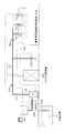
図1は噴霧冷房装置(噴霧冷房設備)として設けた本発明による液剤噴霧装置(液剤噴霧設備)の実施形態を示した説明図である。図1において、噴霧冷房区画A及びBは人が通過するオープンスペース等の冷房対象空間であり、噴霧冷房区画24a及び24bの上方位置、例えば人の通行に妨げとならない高さの位置に、本実施形態による帯電噴霧ヘッド10が設置されており、これらの帯電噴霧ヘッド24a,24bから、それぞれ噴霧区画に対し冷房用水散布を行うようにしている。
FIG. 1 is an explanatory view showing an embodiment of a liquid spraying device (liquid spraying facility) according to the present invention provided as a spray cooling device (spray cooling facility). In FIG. 1, spray cooling sections A and B are cooling target spaces such as an open space through which a person passes, and are positioned above the spray cooling sections 24a and 24b, for example, at a height that does not hinder human traffic. The charged
帯電噴霧ヘッド10に対しては、冷房用水供給設備として設置されたポンプユニット12の吐出側から手動弁(仕切弁)14及び遠隔開閉弁22cを介して配管16が接続され、配管16は分岐後に遠隔開閉弁22a,22bを介して、噴霧冷房区画24a,24bのそれぞれに設置した帯電噴霧ヘッド10に接続している。
A
噴霧冷房区画24a,24bのそれぞれには環境センサ18aが設置され、システム制御盤20aに信号線により接続されている。環境センサ18aは噴霧冷房区画24a,24bにおける気温、湿度、降雨、風速などを計測してシステム制御盤20aに送信する。
An
システム制御盤20aには更に遠隔開閉弁22a〜22dが信号線により接続され、遠隔的に開閉制御できる。システム制御盤20は噴霧冷房設備の停止中は、遠隔開閉弁22a〜22cを閉鎖状態とし、遠隔制御弁22dを開放としている。
Remote open /
またシステム制御盤20aは噴霧冷房の起動時には、ドレン側の遠隔制御弁22dを閉制御すると共に、遠隔制御弁22a〜22cを開制御すると共にポンプユニット12を起動して帯電噴霧ヘッド10に冷房用水を加圧供給する。
Further, the
図2は図1の噴霧冷房区画24aを取り出して示した説明図である。噴霧冷房区画24aの高所には帯電噴霧ヘッド10が設置されている。帯電噴霧ヘッド10に対しては、図1に示したポンプユニット12からの配管16が遠隔開閉弁22aを介して接続されている。
FIG. 2 is an explanatory view showing the spray cooling section 24a of FIG. The charging
また帯電噴霧ヘッド10の上部には電圧印加部15が設置されており、後の説明で明らかにするように、帯電噴霧ヘッド10に所定の電圧を印加して、帯電噴霧ヘッド10から噴射する噴霧水を帯電させて噴霧できるようにしている。
In addition, a
図3は図1及び図2に示した帯電噴霧ヘッド10の実施形態であり、その縦断面を示している。また図4には、帯電噴霧ヘッド10を天井設置状態で下側(床側)から見た説明図を示す。
FIG. 3 shows an embodiment of the charging
図3及び図4において、帯電噴霧ヘッド10は上下に分割した金属製のボディ36,38をボルト37で連結固定しており、ポンプユニット12からの配管16に接続した立下り配管34の先端にボディ36をねじ込み固定している。ボディ36,38の内部流路には円筒状の水側電極部(液剤側電極部)46が組み込まれている。水側電極部46は導電性を持つ金属材料で作られ、更に絶縁材料で被覆されており、金属製のボディ36,38に対し電気的に絶縁されている。
In FIG. 3 and FIG. 4, the charging and spraying
水側電極部46に対しては、図2に示したように、上部に設置している電圧印加部15から引き出されたアースケーブル54が接続されている。このアースケーブル54の接続で、水側電極部46を接地するようにしている。
As shown in FIG. 2, the water-
下部に配置したボディ38の内部流路の先端には絶縁性のスペーサ43を介してノズル部40が形成される。ノズル部40の噴射側には偏向噴霧部として機能するデフレクター42が配置される。デフレクター42はボディ38内の水側電極部46に続いて絶縁部材43を介して組込み固定したデフレクター支持部44から延在したロッド45の先端に設けられ、ノズル部40前方(図示下方)の空間に対向配置されている。
A
本実施形態において、デフレクター42は所定の頂角θをもった円錐状板体であり、ノズル部40から出た液剤を円錐状面に沿って偏向し、薄膜流56に変換して放射(噴霧)する。デフレクター42により形成された薄膜流56は、分裂分離部P付近から分裂分離して粒子群流58となって放射され、模式的に図示した噴霧パターン60のように噴霧される。
In the present embodiment, the
ボディ38には下部に開口した筒状のフレーム50がボルト37により組付け固定されている。フレーム50はその開口端を分裂分離部Pよりも下部、即ち噴霧空間側に位置させており、更に分裂分離部Pの近傍となる内周面に円環状の誘導電極部48を配置している。
A
誘導電極部48は導電性の部材で形成されると共に絶縁材料で被覆されており、金属製のフレーム50及び噴霧される液剤に対し電気的に絶縁されている。
The
フレーム50の下部内周側に配置した誘導電極部48に対しては、図2に示した電圧印加部15から引き出された電圧印加ケーブル52が接続されている。
A
なお図3では、誘導電極部48を例えば薄膜流56の分裂分離部Pの上流方向に10mm以下、下流方向に30mm以下、また薄膜流56の表面から20mm以下となる領域内に配置している。
In FIG. 3, the
ここで、本実施形態の帯電噴霧ヘッド10に使用している水側電極部46及び誘導電極部48としては、導電性を有する金属以外に、導電性を有する樹脂、繊維束、ゴム等であってもよく、更にこれらを組合せた複合体であってもよい。
Here, the water-
帯電噴霧ヘッド10から液剤を噴霧する際には、図2に示した電圧印加部15が図1に示す連動制御中継装置20からの制御信号により動作し、水側電極部46をアース側とし、誘導電極部48に対し例えば数KVから十数KV程度の直流、交流又はパルス状となる印加電圧を印加する。発明者の実験によれば、印加電圧は20KVを超えない範囲とするのが好ましいが、これに限定されるものではない。
When spraying the liquid agent from the charging
このように水側電極部46と誘導電極部48との間に例えば数KVとなる電圧が加えられると、この電圧印加によって外部電界が生じ、ノズル部40から噴射した液剤がデフレクター42の円錐状面に沿った薄膜流56となり、薄膜流56が分裂分離部P付近から分裂分離を始めて粒子群流58に変換される噴射過程を通じて噴射粒子が帯電され、帯電された噴射粒子を外部に噴霧することができる。
Thus, when a voltage of, for example, several KV is applied between the water-
なお、ノズル部40から噴射した液剤をデフレクター42で偏向する場合、剥離や飛散等により液剤の一部が誘導電極部48に接触する場合があるが、誘導電極部48は絶縁材料で被覆されているため、液剤が接触して短絡や電荷の中和が生じることなく、液剤に帯電させることができる。
In addition, when the liquid agent sprayed from the
図5はある条件における噴霧量と比電荷の関係を、デフレクターを設けた本実施形態による帯電噴霧ヘッドとデフレクターを設けない従来ヘッドの場合とで対比した例を模式的に示したグラフ図である。 FIG. 5 is a graph schematically showing an example in which the relationship between the spray amount and specific charge under a certain condition is compared between the charged spray head according to the present embodiment provided with a deflector and the conventional head not provided with a deflector. .
図5において、特性Bは従来の帯電噴霧ヘッドの特性であり、定常的な帯電電圧を引火した場合である。単位時間当りの噴霧量の増加に対し、帯電量を示す比電荷が大きく減少しているが、これに対し本実施形態の帯電噴霧ヘッド10にあっては、例えば特性Aのように、噴霧量の増加に対して比電荷の減少が少ない。図5の例では、本実施形態のノズルの、噴霧量7[リットル/min]における比電荷(特性Aのa点)は、従来ノズルの噴霧量1.5[リットル/min]における比電荷(特性Bのb点)に相当するレベルとなっている。
In FIG. 5, a characteristic B is a characteristic of a conventional charging spray head, and is a case where a steady charging voltage is ignited. As the spray amount per unit time increases, the specific charge indicating the charge amount greatly decreases. On the other hand, in the charged
このように、本実施形態の帯電噴霧ヘッド10によれば、従来の帯電噴霧ヘッドにおける噴霧量増加に伴い単位水量当りの帯電量が大きく減少してしまうという問題を解決し、高効率で帯電させることができるので、噴霧量の多い帯電噴霧ヘッドでありながら、帯電量の大きな噴霧を行うことができる。
As described above, according to the charging
また、ノズル部40から噴射した液剤をデフレクター42により薄膜流56を経て粒子群流58に変換して噴霧するので、デフレクター42の頂角θを適宜設定することにより、従来の帯電噴霧ヘッドに比べ広角の帯電噴霧が容易に実現でき、帯電ロスを抑えつつ散水量を増加させることができるため十分な飛距離が得られ、広範囲に帯電液剤を噴霧して付着効率などの高い帯電噴霧効果を得ることができる。
Further, since the liquid sprayed from the
次に図1の実施形態における監視動作を説明する。システム制御盤20は例えばタイマにより設定した冷房起動時間への到達を判別すると、ドレン側の遠隔開閉弁22dを閉制御すると共に遠隔開閉弁22a〜22cを開制御すると共にポンプユニット12を起動し、水源から冷房用水をくみ上げて汲み上げて加圧し、冷房用水を配管16に供給する。
Next, the monitoring operation in the embodiment of FIG. 1 will be described. When the
システム監視盤20による起動はタイマによる時間設定以外に、管理者による手動操作、噴霧冷房区画24a,24bに設置している環境センサ18からの気温、湿度、降雨、風速などの計測データから所定の起動条件が得られた場合の自動起動などであっても良い。
In addition to the time setting by the timer, the activation by the
システム制御盤20はポンプユニット20の起動による冷房用水の加圧供給と共に、図2に示す帯電噴霧ヘッド10の近傍に設けている電圧印加部15に対し起動信号を送り、この起動信号を受けて電圧印加部15は、帯電噴霧ヘッド10に対し例えば数キロボルトとなる直流印加電圧を供給する。
The
このため図3に示した帯電噴霧ヘッド10にあっては、ノズル部40から噴射された冷房用水をデフレクター42により偏向して薄膜流56を形成した後に粒子群流58に分裂分離して噴霧する際に、アースケーブル54が接続された水側電極部46を基準電位(アース)として、電圧印加ケーブル52が接続された誘導電極部48側に例えば数キロボルトの電圧が所定パターンで印加され、この電圧印加により生じた外部電界を誘導電極部44を通過する分裂分離を始めた粒子群流58に印加し、噴射粒子に帯電させて噴霧することができる。
For this reason, in the charging
図2に取り出して示すように、帯電噴霧ヘッド10から噴霧冷房区画24aに向けて噴霧された水粒子は、このようにして水粒子が帯電しているため、帯電によるクーロン力により、区画内を通過する人の皮膚に効率良く付着し、皮膚に付着して蒸発する際に気化熱を奪うことで高い清涼感が得られる。
As shown in FIG. 2, since the water particles sprayed from the charging
更に図3の帯電噴霧ヘッド10にあっては、例えば水側電極部40を0ボルトとし、リング状誘導電極部44に対しプラスの直流電圧を印加した場合には、噴霧される水粒子はマイナスの電荷のみに帯電している。このようにマイナスの電荷のみに帯電した水粒子を噴霧した場合には、空間中で帯電した水粒子間には斥力が働き、これによって水粒子が衝突会合して成長落下する確率が小さくなり、空間中に滞留する水粒子の密度が高くなり、噴霧水混じりの見かけ上の空気の比重が帯電させないときより増加し、上方へと散逸する傾向を抑制することで、冷房効果が増加する。
Further, in the charging
更に、帯電噴霧ヘッド10からの噴霧水をマイナス帯電させることで、いわゆる自然の滝で発生していると言われているレナード効果と同様の状態を作り出すことができ、清涼感を増加させることができる。
Further, by negatively charging the spray water from the charging
図6は本実施形態の電圧印加部15から帯電噴霧ヘッド10に加える印加電圧を示したタイムチャートである。
FIG. 6 is a time chart showing an applied voltage applied to the charging
図6(A)は+Vの直流電圧を印加する場合であり、この場合には、マイナスに帯電した水粒子が連続的に噴霧される。 FIG. 6A shows a case where a DC voltage of + V is applied. In this case, negatively charged water particles are continuously sprayed.
図6(B)は−Vの直流電圧を印加する場合であり、この場合には、プラスに帯電した水粒子が連続的に噴霧される。 FIG. 6B shows a case where a DC voltage of −V is applied. In this case, positively charged water particles are continuously sprayed.
図6(C)は±Vの交流電圧を印加する場合であり、この場合には、プラスの半サイクルの期間に交流電圧の変化に応じてマイナスに帯電した水粒子が噴霧され、マイナスの半サイクルの期間に交流電圧の変化に応じてプラスに帯電した水粒子が交互に噴霧される。 FIG. 6C shows a case where an AC voltage of ± V is applied. In this case, negatively charged water particles are sprayed in accordance with a change in the AC voltage during the positive half cycle, and the negative half voltage is sprayed. During the cycle, positively charged water particles are alternately sprayed according to the change in AC voltage.
図6(D)は+Vのパルス状電圧を所定のインターバルを空けて繰り返し印加する場合であり、この場合には、マイナスに帯電した水粒子が間欠的に噴霧され、電圧を印加していない期間には、帯電していない水粒子の噴霧となる。 FIG. 6D shows a case where a pulsed voltage of + V is repeatedly applied at predetermined intervals. In this case, a period in which negatively charged water particles are intermittently sprayed and no voltage is applied. In this case, the water particles are uncharged.
図6(E)は−Vのパルス状電圧を所定のインターバルを空けて繰り返し印加する場合であり、この場合には、プラスに帯電した水粒子が間欠的に噴霧され、電圧を印加していない期間には、帯電していない水粒子の噴霧となる。 FIG. 6E shows a case where a pulsed voltage of −V is repeatedly applied at a predetermined interval. In this case, positively charged water particles are intermittently sprayed and no voltage is applied. During the period, it becomes a spray of uncharged water particles.
図6(F)は±Vのパルス状電圧を所定のインターバルを空けて交互に繰り返し印加する場合であり、この場合には、マイナスに帯電した水粒子とプラスに帯電した水粒子がインターバルを空けて交互に噴霧され、電圧を印加していない期間には、帯電していない水粒子の噴霧となる。このようなインターバルを設けずに±Vのパルス状電圧を交互に繰り返し印加しても良い。 FIG. 6 (F) shows a case where a pulsed voltage of ± V is repeatedly applied alternately at predetermined intervals. In this case, negatively charged water particles and positively charged water particles are spaced apart. During the period when the voltage is not applied, the water particles are uncharged. A pulse voltage of ± V may be alternately applied repeatedly without providing such an interval.
図6(C)〜(F)に例示した印加電圧パターンにおける印加周期や転極周期は適宜に定めることができ、また図6(A)〜(F)の各パターンのうち福奇数を組み合わせたパターンと擦ること等もできる。 The application period and the inversion period in the applied voltage pattern illustrated in FIGS. 6C to 6F can be determined as appropriate, and the odd and odd numbers of the patterns in FIGS. 6A to 6F are combined. It can also be rubbed with a pattern.
図6に例示した各パターンの印加電圧を帯電噴霧ヘッド10に供給する電圧印加部15としては、制御入力付きの市販の昇圧ユニットを利用することができる。市販の昇圧ユニットには、例えば入力にDC0〜20ボルトを加えると出力にDC〜20キロボルトを出力するものがあり、このような昇圧ユニットが利用できる。
As the
図7は本発明による帯電噴霧ヘッドの他の実施形態であり、その縦断面を示している。また図8には、図7の帯電噴霧ヘッドを天井設置状態で下側(床側)から見た説明図を示す。本実施形態の帯電噴霧ヘッドは広範囲に噴霧するために2重円錐状(ダブルコーン状)に液剤粒子群流を帯電噴霧するようにしたことを特徴とする。 FIG. 7 shows another embodiment of the charging spray head according to the present invention, and shows a longitudinal section thereof. FIG. 8 is an explanatory view of the charging spray head of FIG. 7 viewed from the lower side (floor side) in the ceiling installation state. The charging spray head of this embodiment is characterized in that the liquid agent particle group flow is charged and sprayed in a double cone shape (double cone shape) for spraying over a wide range.
図7及び図8において、帯電噴霧ヘッド10は上下に分割した金属製のボディ36,38をボルト37で連結固定しており、ポンプユニット12からの配管16に接続した立下り配管34の先端にボディ36をねじ込み固定している。ボディ36,38の内部流路には円筒状の水側(液剤側)電極部46が組み込まれている。水側電極部46は導電性を持つ金属材料で作られ、更に絶縁材料で被覆されており、金属製のボディ36,38に対し電気的に絶縁されている。また水側電極部46の下側には絶縁性のスペーサ43が配置される。
7 and 8, the charging
水側電極部46に対しては、図2に示したように、上部に設置している電圧印加部15から引き出されたアースケーブル54が接続されている。このアースケーブル54の接続で、水側電極部46を接地するようにしている。
As shown in FIG. 2, the water-
下部に配置したボディ38の内部流路の先端にはノズル部70が形成される。本実施形態のノズル部70は、図7に示す如く、中心位置に配置したデフレクター支持部44−1から延在したロッド45の先端側の空間に第1偏向噴霧部材として第1デフレクター42−1を配置し、また、同軸に配置したデフレクター支持部44−2に円筒基部をねじ込み支持して第1デフレクター42−1の後方となる先端側の空間に第2噴霧偏向部材として第2デフレクター42−2を配置している。なお。43は絶縁部材である。
A
第2デフレクター42−2は中央にノズル穴を開口形成し、先端外周側を外側に向けて円錐状に広げた形状であり、中央のノズル穴にはロッド45は挿通されるようになるが、この挿通部に於けるノズル穴とロッド45との隙間によって、第1デフレクター42−1に向けて液剤を放出する第1ノズル部40−1を形成している。
The second deflector 42-2 has a shape in which a nozzle hole is formed at the center and the tip outer peripheral side is widened in a conical shape, and the
またノズル部70のノズル開口と、このノズル開口に挿通して第2デフレクター40−2を支持している円筒基部との間にはリング状の隙間(リング状ノズル穴)が形成され、このリング状の隙間が第2デフレクター42−2に向けて液剤を放出する第2ノズル部40−2を形成している。
A ring-shaped gap (ring-shaped nozzle hole) is formed between the nozzle opening of the
本実施形態において、第1デフレクター42−1は所定の頂角θ1をもった円錐状体であり、第1ノズル部40−1から射出された液剤を円錐状面に沿って偏向し、薄膜流56−1に変換して放射する。第1デフレクター42−1により形成された薄膜流56−1は、分裂分離部P1付近から分裂分離して第1粒子群流58−1となって放射され、模式的に図示した噴霧パターン60−1のように噴霧される。 In the present embodiment, the first deflector 42-1 is a conical body having a predetermined apex angle θ1, and deflects the liquid agent ejected from the first nozzle part 40-1 along the conical surface, so that the thin film flow Convert to 56-1 and radiate. The thin film flow 56-1 formed by the first deflector 42-1 is split and separated from the vicinity of the splitting separation portion P1 and emitted as the first particle group flow 58-1, and is schematically shown as a spray pattern 60-. Sprayed as in 1.
また第2デフレクター42−2は、第1デフレクター40−1の頂角θ1より大きな所定の頂角θ2をもった円錐状体を円筒基部の先端に図示の如く形成しており、リング状の隙間をもつ第2ノズル部40−2から射出された液剤を円錐状面に沿って広角に偏向し、薄膜流56−2に変換して放射する。第2デフレクター42−2により形成された薄膜流56−2は、分裂分離部P2付近から分裂分離して第2粒子群流58−2となって放射され、模式的に図示した噴霧パターン60−2のように、第1デフレクター40−1による噴霧パターン60−2の外側を覆うように広角に噴霧され、これによって2重円錐状(ダブルコーン状)の広域を均一的にカバーする噴霧パターンを形成する。 The second deflector 42-2 is formed with a conical body having a predetermined apex angle θ2 larger than the apex angle θ1 of the first deflector 40-1 at the tip of the cylindrical base as shown in the figure, and has a ring-shaped gap. The liquid agent ejected from the second nozzle part 40-2 having the above is deflected at a wide angle along the conical surface, converted into a thin film flow 56-2 and radiated. The thin film flow 56-2 formed by the second deflector 42-2 is split and separated from the vicinity of the splitting portion P2 and emitted as the second particle group flow 58-2, and the spray pattern 60- schematically illustrated is shown. 2, the spray pattern is sprayed at a wide angle so as to cover the outside of the spray pattern 60-2 by the first deflector 40-1, thereby uniformly covering a wide area of a double cone shape (double cone shape). Form.
ボディ38には下側に開口した筒状のフレーム50がボルト37により組付け固定されている。フレーム50はその開口端を第2デフレクター42−2で偏向形成された薄膜流56−2の分裂分離部P2よりも下部、即ち噴霧空間側に位置させており、更に分裂分離部P2の近傍となる内周面に円環状の第2誘導電極部48−2を配置している。
A
またフレーム50の下方にはホルダアーム72によりリング状のフレーム74が支持されている。フレーム74はその下側の開口端を第1デフレクター40−1で偏向された薄膜流56−1の分裂分離部P1よりも下部、即ち噴霧空間側に位置させており、更に分裂分離部P1の近傍となる内周面に円環状の第1誘導電極部48−1を配置している。
A ring-shaped
第1誘導電極部48−1及び第2誘導電極48−2は導電性の部材で形成されると共に絶縁材料で被覆されており、金属製のフレーム50,74及び噴霧される液剤に対し電気的に絶縁されている。 The first induction electrode portion 48-1 and the second induction electrode 48-2 are formed of a conductive member and coated with an insulating material, and are electrically connected to the metal frames 50 and 74 and the sprayed liquid agent. Is insulated.
フレーム50,74に配置した第1誘導電極部48−1及び第2誘導電極48−2に対しては、図2に示した電圧印加部15から引き出された電圧印加ケーブル52が接続されている。
A
また第1誘導電極部48−1及び第2誘導電極48−2は、例えば薄膜流56−1,56−2の分裂分離部P1,P2の上流方向に10mm以下、下流方向に30mm以下、また薄膜流56−1,56−2の表面から20mm以下となる領域内に配置している。 In addition, the first induction electrode part 48-1 and the second induction electrode 48-2 are, for example, 10 mm or less upstream of the splitting separation parts P1 and P2 of the thin film flows 56-1 and 56-2, 30 mm or less downstream, It arrange | positions in the area | region which is 20 mm or less from the surface of the thin film flows 56-1, 56-2.
ここで、本実施形態の帯電噴霧ヘッド10に使用している水側電極部46、第1誘導電極部48−1及び第2誘導電極部48−2としては、導電性を有する金属以外に、導電性を有する樹脂、繊維束、ゴム等であってもよく、更にこれらを組合せた複合体であってもよい。
Here, as the water
図7、図8の帯電噴霧ヘッド10から液剤を噴霧する場合には、図2に示した電圧印加部15が図1に示すシステム制御盤20aからの制御信号により動作し、水側電極部46をアース側とし、第1誘導電極部48−1及び第2誘導電極48−2に対し例えば数KVから十数KV程度の直流、交流又はパルス状となる印加電圧を印加する。発明者の実験によれば、印加電圧は20KVを超えない範囲とするのが好ましいが、これに限定されるものではない。
When spraying the liquid agent from the charging
このように水側電極部46と第1誘導電極部48−1及び第2誘導電極部48−2の間に例えば水側電極部46の基準電位(アース)に対し数KVとなる電圧が所定パターンで印加され、この電圧印加によって外部電界が生じ、第1ノズル部40−1及び第2ノズル部40−2から噴射した液剤が第1デフレクター42−1及び第2デフレクター42−2の円錐状面に沿った薄膜流56−1,56−2となり、薄膜流56−1.56−2が分裂分離部P1,P2付近から分裂分離を始めて第1粒子群流58−1及び第2粒子群流58−2に変換される噴射過程を通じて液剤の噴射粒子が帯電され、帯電された噴射粒子を外部に広域を均一的にカバーする2重円錐状(ダブルコーン状)のパターンとして帯電噴霧することができる。
Thus, for example, a voltage of several KV is predetermined between the water-
図9は本発明による噴霧防塵設備の実施形態を示した説明図である。図9において、噴霧防塵区画24cは塵埃が発生する作業施設等であり、噴霧防塵区画24cの上方位置、例えば作業に妨げとならない高さの位置に、本実施形態による帯電噴霧ヘッド10が設置されている。
FIG. 9 is an explanatory view showing an embodiment of the spray dustproof equipment according to the present invention. In FIG. 9, the spray dust-proof section 24 c is a work facility where dust is generated, and the charged
帯電噴霧ヘッド10に対しては、液剤供給設備として設置された水源水槽11からの水を加圧供給するポンプユニット12の吐出側から手動弁(仕切弁)14及び遠隔開閉弁22cを介して配管16が接続され、配管16は遠隔開閉弁22aを介して、噴霧防塵区画24cに設置した帯電噴霧ヘッド10に接続している。帯電噴霧ヘッド10は図3又は図7の実施形態に示したものを使用する。
For the charging
噴霧防塵区画24cには環境センサ18bが設置され、システム制御盤20bに信号線により接続されている。環境センサ18bは噴霧防塵区画24cにおける塵埃濃度などを計測してシステム制御盤20bに送信する。
An
システム制御盤20bには更に遠隔開閉弁22a,22c,22dが信号線により接続され、遠隔的に開閉制御できる。システム制御盤20bは噴霧防塵設備の停止中は、遠隔開閉弁22a,22cを閉鎖状態とし、遠隔制御弁22dを開放としている。
Remote on / off
またシステム制御盤20aは噴霧防塵設備の起動時には、ドレン側の遠隔制御弁22dを閉制御すると共に、遠隔制御弁22a,22cを開制御すると共にポンプユニット12を起動して水源水槽11からの水を帯電噴霧ヘッド10に加圧供給して噴霧防護区画24aに帯電噴霧させる。
Further, the
帯電噴霧ヘッド10から噴霧防塵区画24cに帯電した水(液剤)粒子を帯電噴霧すると、帯電噴霧している水粒子のクーロン力により、同じく帯電状態にある塵埃粒子を捕集して床面に速やかに降下させ、これによって大幅な防塵作用が発揮される。
When charged water (liquid agent) particles are charged and sprayed from the
図10は本発明による農薬噴霧兼植物育成設備の実施形態を示した説明図である。図10において、農薬噴霧兼植物育成区画24dは植物を育成する温室等の施設等であり、農薬噴霧兼植物育成区画24dの上方位置、例えば作業に妨げとならない高さの位置に、本実施形態による帯電噴霧ヘッド10が設置されている。帯電噴霧ヘッド10は図3又は図7の実施形態に示したものを使用する。
FIG. 10 is an explanatory view showing an embodiment of the pesticide spraying and plant growing facility according to the present invention. In FIG. 10, a pesticide spraying / plant growing section 24d is a facility such as a greenhouse for growing plants, and the present embodiment is positioned above the pesticide spraying / plant growing section 24d, for example, at a height that does not hinder work. The charging
ポンプユニット12の吸込み側は遠隔開閉弁22e,22fを介して農薬タンク26と水源水槽11に接続され、農薬タンク26からの農薬または水源水槽11からの水をポンプユニット12から加圧供給する。ポンプユニット12の吐出側は手動弁(仕切弁)14及び遠隔開閉弁22cを介して配管16に接続され、配管16は遠隔開閉弁22aを介して、農薬噴霧兼植物育成区画24dに設置した帯電噴霧ヘッド10に接続している。
The suction side of the
農薬噴霧兼植物育成区画24dには環境センサ18cが設置され、システム制御盤20bに信号線により接続されている。環境センサ18bは農薬噴霧兼植物育成区画24dにおける温度、湿度などを計測してシステム制御盤20cに送信する。
An
システム制御盤20cには更に遠隔開閉弁22a,22c〜22fが信号線により接続され、遠隔的に開閉制御できる。システム制御盤20cは設備の停止中は、遠隔開閉弁22a,22c,22e,22fを閉鎖状態とし、遠隔制御弁22dを開放としている。
Remote on / off
農薬噴霧を行う場合、システム制御盤20aはドレン側の遠隔制御弁22dを閉制御すると共に、遠隔制御弁22eは閉状態としたまま、遠隔制御弁22a,22c,22fを開制御すると共にポンプユニット12を起動して農薬タンク26からの農薬液剤を帯電噴霧ヘッド10に加圧供給して農薬噴霧兼植物育成区画24dに帯電噴霧させる。
When pesticide spraying is performed, the
帯電噴霧ヘッド10から農薬噴霧兼植物育成区画24dに農薬液剤粒子を噴霧すると、農薬液剤粒子は帯電しているため、帯電によるクーロン力により育成中の植物に効率良く付着する。また回り込み効果により植物の葉の裏面といったあらゆる面への付着が起こり、従来のように非帯電の水粒子を噴霧した場合に比べ、燃焼剤に対する付着効果が大幅に増大し、高い付着効率が得られる。
When the agrochemical liquid particles are sprayed from the
また農薬噴霧を行っていない場合は植物育成制御を行っており、システム制御盤20aはドレン側の遠隔制御弁22dを閉制御すると共に、遠隔制御弁22a,22c,22eを開制御すると共にポンプユニット12を起動して水源水槽11からの水を帯電噴霧ヘッド10に加圧供給して農薬噴霧兼植物育成区画24dに帯電噴霧させる。
In addition, when the pesticide spray is not performed, plant growth control is performed, and the
帯電噴霧ヘッド10から農薬噴霧兼植物育成区画24dに農薬液剤粒子を噴霧すると、農薬液剤粒子はマイナスに帯電しているため、いわゆる自然の滝で発生していると言われているレナード効果と同様の状態を作り出すことができ、植物の育成に好影響を及ぼすことができる。
When the pesticide spray particles are sprayed from the
なお、システム制御盤20cによる農薬噴霧と育成用水噴霧はタイマ制御などにより自動的に行うようにしても良い。また図10の実施形態は、農薬噴霧兼植物育成設備としているが、ポンプユニット12の吸込み側に農薬タンク26のみを設けた農薬噴霧設備またはポンプユニット12の吸込み側に水源水槽11のみを設けた植物育成設備としてもよい。更に、植物育成のための帯電噴霧は、植物育成のみならず植物の養成、発根、貯蔵等にもそのまま適用できる。
The pesticide spraying and the growth water spraying by the
図11は本発明による液剤噴霧設備の他の実施形態を示した説明図であり、水に所望の薬液を混合して噴霧するようにしたことを特徴とする。 FIG. 11 is an explanatory view showing another embodiment of the liquid spraying equipment according to the present invention, which is characterized in that a desired chemical is mixed and sprayed in water.
図11において、液剤噴霧区画24eは適宜の区画、例えば空調区画などであり、噴霧防塵区画24eの上方位置、例えば人の移動の妨げとならない高さの位置に、本実施形態による帯電噴霧ヘッド10が設置されている。帯電噴霧ヘッド10は図3又は図7の実施形態に示したものを使用する。
In FIG. 11, a liquid spraying section 24e is an appropriate section, for example, an air conditioning section, and is located above the spraying dustproof section 24e, for example, at a height that does not hinder human movement. Is installed. The charging
帯電噴霧ヘッド10に対しては、水源水槽11からの水を加圧供給するポンプユニット12が設置され、ポンプユニット12の吐出側に手動弁(仕切弁)14及び遠隔開閉弁22cを介して配管16が接続され、配管16には遠隔開閉弁22aを介して、液剤噴霧区画24eに設置した帯電噴霧ヘッド10を接続している。
A
手動弁14と遠隔開閉弁22cの間の配管16には混合器30が設けられ、混合器30には薬液タンク28が接続されている。薬液タンク28には適宜の薬液が貯留されており、配管16からの加圧水の導入により隔膜で仕切られたタンク内に貯留している薬液を混合器30に押出し、所定の混合割合となるようにポンプユニット12から加圧供給された水に混合して帯電噴霧ヘッド10に供給するようにしている。
A pipe 30 between the
混合器30により混合する薬剤タンク28の薬液としては例えば消臭剤とし、消臭剤を混合した液剤を帯電噴霧ヘッド10に供給して液剤噴霧区画24eに帯電噴霧することで、空気中に浮遊している匂いの原因となる粒子に吸着して消臭する防臭設備を構築する。
The chemical liquid in the
薬剤噴霧区画24eには環境センサ18dが設置され、システム制御盤20dに信号線により接続されている。環境センサ18dは薬液噴霧区画24dにおける例えばアンモニア濃度などを計測してシステム制御盤20dに送信する。
An
システム制御盤20dには更に遠隔開閉弁22a,22c,22dが信号線により接続され、遠隔的に開閉制御できる。システム制御盤20dは液剤噴霧設備の停止中は、遠隔開閉弁22a,22cを閉鎖状態とし、遠隔制御弁22dを開放としている。
Remote on / off
またシステム制御盤20dは液剤噴霧設備の起動時には、ドレン側の遠隔制御弁22dを閉制御すると共に、遠隔制御弁22a,22cを開制御すると共にポンプユニット12を起動して水源水槽11からの水に混合器30で薬剤タンク28から供給された消臭剤などの薬剤を所定割合で混合し、帯電噴霧ヘッド10に加圧供給して液剤噴霧区画24dに帯電噴霧させる。
The
帯電噴霧ヘッド10から液剤噴霧区画24dに帯電した消臭剤入りの水粒子を噴霧すると、帯電している水粒子のクーロン力により、同じく帯電状態にあるアンモニアなどの粒子を捕集して床面に速やかに降下させ、これによって大幅な消臭作用が発揮される。また消臭剤と芳香剤を水に混合して帯電噴霧することで、消臭すると共に快適な匂いを生成して清浄感を高めることができる。
When the charged water particles containing the deodorant are sprayed from the charging
図12は、図2の噴霧冷房区画にハンディ型のノズル装置をホース接続して使用する本発明による液剤噴霧設備の他の実施形態を示した説明図である。 FIG. 12 is an explanatory view showing another embodiment of the liquid agent spraying equipment according to the present invention in which a handy type nozzle device is connected to the spray cooling section of FIG. 2 by using a hose.
図12において、噴霧冷房区画24aの高所には帯電噴霧ヘッド10が設置され、帯電噴霧ヘッド10に対しては、図1に示したポンプユニット12からの配管16が遠隔開閉弁22aを介して接続されている。帯電噴霧ヘッド10の上部には電圧印加部15が設置されており、帯電噴霧ヘッド10に所定の電圧を印加して、帯電噴霧ヘッド10から噴射する噴霧水を帯電させて噴霧できるようにしている。
In FIG. 12, the charging
配管16は噴霧冷房区画24aの壁面下部まで立ち下げられ、そこに仕切弁75を介してホース接続口76を設けている。ホース接続口76にはホース78を介してノズル装置100が接続されている。ノズル装置100には帯電噴霧ヘッドと電圧印加装置が組み込まれており、ノズル装置100から噴射する冷房用の噴霧水を帯電させて噴霧できるようにしている。
The
図13は図12のノズル装置の実施形態を示した断面図である。図13において、ノズル装置100は、本体102の内部に配置した導電性の金属からなる筒本体114の先端側に帯電噴霧ヘッド10を設け、根元側にホース接続口106を設け、ホース接続口106には図12に示したように、仕切弁75を介してホース76が接続され、冷房用水が加圧供給され、帯電噴霧ヘッド10から帯電噴霧される。
FIG. 13 is a cross-sectional view showing an embodiment of the nozzle device of FIG. In FIG. 13, the
本体102の先端に設けた帯電噴霧ヘッド10は、図3に示したと同様な構造であり、左右に分割した金属製のボディ36,38を備え、ボディ38は流入口36aを延在し、流入口36aを筒本体114の先端に挿入した状態でボルト37により連結固定している。ボディ36,38の内部流路には円筒状の水側電極部(液剤側電極部)46が組み込まれ、水側電極部46は導電性を持つ金属材料で作られ、更に絶縁材料で被覆されており、金属製のボディ36,38に対し電気的に絶縁されている。
The charging
ボディ38の内部流路の先端には絶縁性のスペーサ43を介してノズル部40が形成され、ノズル部40の噴射側にはデフレクター42が配置される。デフレクター42はデフレクター支持部44から延在したロッド45の先端に設けられ、ノズル部40前方の空間に対向配置されている。
A
ボディ38には前方に開口すると共に周囲に複数の吸気穴116を開口した筒状のフレーム50がボルト37により組付け固定されている。フレーム50は前方の開口端を噴霧空間側に位置させており、先端内周面に円環状の誘導電極部48を配置している。誘導電極部48は導電性の部材で形成されると共に絶縁材料で被覆されており、金属製のフレーム50及び噴霧される液剤に対し電気的に絶縁されている。
A
デフレクター42はノズル部40から出た液剤を円錐状面に沿って偏向し、薄膜流56に変換して放射(噴霧)する。デフレクター42により形成された薄膜流56は、誘導電極部48の付近から薄膜流56が分裂分離して粒子群流58となって噴霧される。
The
本体102に対しては握り部108を備えたフレーム110が一体に設けられ、フレーム110の握り部108側には噴射粒子を帯電して放射させるための電圧印加スイッチ124を設けている。本体102及びフレーム110は合成樹脂などの絶縁材料で作られている。
A
フレーム110の握り部108の内部には、電池118と電圧印加装置120が組み込まれている。電池118は電圧印加装置120に直流電源を供給する。電圧印加装置120は、誘導電極配線122により帯電噴霧ヘッド10に設けた誘導電極部48に接続し、また水側電極配線124により水側電極部46に接続している。更に、握り部108の指を掛ける位置に設けた電圧印加スイッチ112に配線接続している。
A
電圧印加装置120は、電圧印加スイッチ112をオン操作すると、水側電極部46をアース側とし、誘導電極部48に対し例えば数KVから十数KV程度の直流、交流又はパルス状となる印加電圧を印加する。このように水側電極部46と誘導電極部48との間に例えば数KVとなる電圧が加えられると、この電圧印加によって外部電界が生じ、ノズル部40から噴射した液剤がデフレクター42の円錐状面に沿った薄膜流56となり、薄膜流56が誘導電極部48付近を通過する場合に分裂分離を始めて粒子群流58に変換される噴射過程を通じて噴射粒子が帯電され、帯電された噴射粒子を外部に噴霧することができる。
When the
なお、図13のノズル装置100は図3の帯電噴霧ヘッド10をノズル先端に設けた場合を例にとっているが、更に噴霧範囲を広範囲としたい場合には図7に示した構造の帯電噴霧ヘッド10を設ければ良い。
The
また図12に示したハンディ型のノズル装置100は、図9の噴霧防塵区間24c、図10の農薬噴霧兼植物育成区間24d、液剤噴霧区画24eについても同様に適用することができる。
Further, the handy
図14は、背負型の動力噴霧機として使用する本発明による液剤噴霧装置の他の実施形態を示した説明図であり、図14(A)に背面を、図14(B)に側面を示している。 FIG. 14 is an explanatory view showing another embodiment of the liquid agent spraying device according to the present invention used as a backpack type power sprayer. FIG. 14 (A) shows the back surface, and FIG. 14 (B) shows the side surface. ing.
図14において、動力噴霧機130は背負いバンド136を装着した背当て部134の下部に架台132を配置し、背当て部134の上部にポリエチレン等で作られた蓋140を備えたタンク138を配置し、ここに噴霧する例えば冷房用水などの液剤を収納している。
In FIG. 14, the
架台132には駆動源となるエンジン142と、エンジン142により駆動されてタンク138の液剤を加圧供給するポンプ144が搭載され、ポンプ144のホース接続口148にホース150を介してノズル装置152を接続している。
The
ノズル装置152は本体154の付け根側にコック弁155を介してポンプ144からのホース150を接続し、本体154の先端に帯電噴霧ヘッド10を装着している。本体154の付け根側には握り部156が形成され、そこに電圧印加スイッチ158を設けている。ノズル装置152の詳細は図13の実施形態と同様な構造であり、本体154が前方に延在されて、その先端に帯電噴霧ヘッド10を装着している点で相違している。
In the
このような動力噴霧機130として構成した本発明の液剤噴霧装置によれば、作業者が動力噴霧機130を装着して作業場所に出向き、エンジン142を始動してポンプ144からタンク138の液剤を加圧してノズル装置152に供給し、噴霧する場合にはノズル装置152に設けたコック弁155を開くことで、帯電噴霧ヘッド10に加圧液剤を供給して噴霧し、この場合に電圧印加スイッチ158をオン操作すると、帯電噴霧ヘッド10に例えば数KVから十数KV程度の直流、交流又はパルス状となる印加電圧が印加され、帯電された噴射粒子を外部に噴霧することができる。
According to the liquid spray device of the present invention configured as such a
図15は、動力噴霧台車として使用する本発明による液剤噴霧装置の他の実施形態を示した説明図である。図15において、動力噴霧台車160は、車輪164により移動自在な台車162に、ポリエチレン等で作られた蓋170を備えたタンク168を搭載して例えば冷房用水などの液剤を収納している。
FIG. 15 is an explanatory view showing another embodiment of the liquid spraying device according to the present invention used as a power spray cart. In FIG. 15, a
また台車162には駆動源となるエンジン172と、エンジン172により駆動されてタンク168の液剤を加圧供給するポンプ174が搭載され、ポンプ174のホース接続口178にホース180を介してノズル装置182を接続している。台車162は手押しハンドル165を持って作業者が手動で移動させる。
The carriage 162 is equipped with an
ノズル装置182は本体184の付け根側にコック弁185を介してポンプ174からのホース180を接続し、本体184の先端に帯電噴霧ヘッド10を装着している。本体184の付け根側には握り部186が形成され、そこに電圧印加スイッチ188を設けている。ノズル装置182の詳細は図13の実施形態と同様な構造であり、本体184が前方に延在されて、その先端に帯電噴霧ヘッド10を装着している点で相違している。
In the
このような移動自在な動力噴霧台車160として構成した本発明の液剤噴霧装置によれば、作業者が台車162を押して作業場所に出向き、エンジン172を始動してポンプ174からタンク168の液剤を加圧してノズル装置182に供給し、噴霧する場合にはノズル装置182に設けたコック弁185を開くことで、帯電噴霧ヘッド10に加圧液剤を供給して噴霧し、この場合に電圧印加スイッチ188をオン操作すると、帯電噴霧ヘッド10に例えば数KVから十数KV程度の直流、交流又はパルス状となる印加電圧が印加され、帯電された噴射粒子を外部に噴霧することができる。
According to the liquid spray device of the present invention configured as such a movable
ここで、図14および図15のノズル装置152,182は図3の帯電噴霧ヘッド10をノズル先端に設けた場合を例にとっているが、更に噴霧範囲を広範囲としたい場合には図7に示した構造の帯電噴霧ヘッド10を設ければ良い。
Here, the
また図14の動力噴霧機130および図15の動力噴霧台車160は駆動源としてエンジン142を設けているが、駆動源としてバッテリーとモータを搭載してポンプを駆動するようにしても良い。また図14の背負い型の動力噴霧機130は駆動源として手動操作により空気を圧縮してタンクの液剤を加圧供給する蓄圧式の噴霧機としても良いし、必ずしも背負い型とせず、手持ちにより運搬可能なハンディ型の噴霧機としても良い。更に、図15の動力噴霧台車としてはエンジンやモータを駆動源とする自走式としても良い。
Moreover, although the
なお、本実施形態で使用する帯電噴霧ヘッド10としては、デフレクター42や42−1、42−2の頂角を適宜調整することで、防護区画の広さに適合した噴霧パターンを確保することができる。
In addition, as the charging
また、上記の実施形態にあっては、誘導電極部48、48−1、48−2として環状電極を使用しているが、それぞれの形状は任意で、例えばデフレクター42、42−1、42−2で生成された薄膜流56、56−1、56−2の流れ方向に略平行な電極面をもつ環状電極を使用してもよい。このように誘導電極部48、48−1、48−2として薄膜流の流れ方向に略平行な環状電極を使用した場合には、電極面内各部と薄膜流表面との距離が均一となり、帯電効率を高めると共に安定した帯電を得ることができる。
Further, in the above-described embodiment, the annular electrodes are used as the
また、帯電噴霧ヘッドへの印加電圧パターンを、水側電極部に対し誘導電極部側をプラスマイナス交互の印加電圧とするか、プラスのみの印加電圧とするか、あるいはマイナスのみの印加電圧とするか、また直流状の印加とするかパルス状の印加とするか、或いは、例えば正弦波状に変化する交流印加等とするかは、噴霧対象や噴霧対象領域、その他各種の条件、状況やその変化等に応じて適宜に定めることができる。 Moreover, the applied voltage pattern to the charging spray head is set so that the induction electrode side is alternately plus or minus applied voltage with respect to the water side electrode part, or only plus voltage is applied, or only minus voltage is applied. Whether to apply a direct current or a pulse, or to apply an alternating current that changes in a sinusoidal shape, for example, whether it is a spray target, a spray target region, various other conditions, situations, or changes thereof It can be appropriately determined according to the above.
また、上記実施形態では基準電圧(電位)を例えばアース(接地)電圧として示したが、基準電圧はこれに限らず、電圧のプラスマイナスについてはこの基準電圧に対する高低を示す概念である。 In the above embodiment, the reference voltage (potential) is shown as, for example, a ground (ground) voltage. However, the reference voltage is not limited to this, and the plus or minus of the voltage is a concept indicating the level of the reference voltage.
また、誘導電極部やデフレクターの数は任意で、例えばそれぞれを3つ組み合わせたトリプルコーン型としてもよい。もちろん、ノズル部の数も任意である。
The number of induction electrode portions and deflectors is arbitrary, and for example, a triple cone type in which three of them are combined may be used. Of course, the number of nozzle portions is also arbitrary.
また、誘導電極部の数とデフレクターの数の組み合わせも任意で、例えば1つの誘導電極部に対して複数のデフレクターを設けるものであっても、複数の誘導電極部に対して1つのデフレクターを設けるものであってもよい。またこのように異なる数の誘導電極部とデフレクターの組み合わせからなるノズル部を複数備えたものであってもよい。 Further, the combination of the number of induction electrode portions and the number of deflectors is also arbitrary. For example, even if a plurality of deflectors are provided for one induction electrode portion, one deflector is provided for a plurality of induction electrode portions. It may be a thing. In addition, a plurality of nozzle portions each composed of a combination of different numbers of induction electrode portions and deflectors may be provided.
また、本発明の帯電噴霧ヘッドおよび帯電噴霧方法は、上記の実施形態に示した以外にも各種の利用が可能である。 The charging spray head and the charging spray method of the present invention can be used in various ways other than those shown in the above embodiments.
また、誘導電極部やデフレクターは必ずしも円錐形状である必要は無く、例えば角錐状
としてもよい。
Further, the induction electrode portion and the deflector do not necessarily have a conical shape, and may be a pyramid shape, for example.
また本発明はその目的と利点を損なうことのない適宜の変形を含み、更に上記の実施形態に示した数値による限定は受けない。
The present invention includes appropriate modifications that do not impair the objects and advantages thereof, and is not limited by the numerical values shown in the above embodiments.
10:帯電噴霧ヘッド
11:水源水槽
12:ポンプユニット
14:手動弁
15:電圧印加部
16:配管
18a〜18d:環境センサ
20a〜20d:システム制御盤
22a〜22f:遠隔開閉弁
24a,24b:噴霧空調区画
24c:噴霧防塵区画
24d:農薬噴霧兼植物育成区画
24e:液剤噴霧区画
26:農薬タンク
28:薬剤タンク
30:混合器
34:立下り配管
36,38:ボディ
40,70:ノズル部
42:デフレクター
42−1:第1デフレクター
42−2:第2デフレクター
43:絶縁部材
44,44−1,44−2:デフレクター支持部
45:ロッド
46:水側電極部
48:誘導電極部
48−1:第1誘導電極部
48−2:第2誘導電極部
50,74:フレーム
52:電圧印加ケーブル
54:アースケーブル
55:ケーブルホルダ
56,56−1,56−2:薄膜流
58:粒子群流
58−1:第1粒子群流
58−2:第2粒子群流
60:噴霧パターン
60−1:第1噴霧パターン
60−2:第2噴霧パターン
P,P1,P2:分裂分離部
75:仕切弁
76,106,148,178:ホース接続口
78,150,180:ホース
100,152,182:ノズル装置
102,154,184:本体
108,156,186:握り部
110:フレーム
112,158,188:電圧印加スイッチ
114:筒本体
116:吸気穴
118:電池
120:電圧印加装置
130:動力噴霧器
132:架台
134:背当て
136:背負いバンド
138,168:タンク
142,172:エンジン
144,174:ポンプ
160:動力噴霧台車
162:台車
164:車輪
165:手押しハンドル
10: Charge spray head 11: Water source water tank 12: Pump unit 14: Manual valve 15: Voltage application unit 16: Piping 18a-18d: Environmental sensors 20a-20d: System control panels 22a-22f: Remote on-off valves 24a, 24b: Spray Air-conditioning section 24c: Spray dust-proof section 24d: Pesticide spraying and plant breeding section 24e: Liquid spray section 26: Pesticide tank 28: Chemical tank 30: Mixer 34: Falling pipe 36, 38: Body 40, 70: Nozzle section 42: Deflector 42-1: 1st deflector 42-2: 2nd deflector 43: Insulating members 44, 44-1, 44-2: Deflector support part 45: Rod 46: Water side electrode part 48: Induction electrode part 48-1: 1st induction electrode part 48-2: 2nd induction electrode part 50, 74: Frame 52: Voltage application cable 54: Earth cable 55: Cable Luda 56, 56-1, 56-2: thin film flow 58: particle group flow 58-1: first particle group flow 58-2: second particle group flow 60: spray pattern 60-1: first spray pattern 60- 2: Second spray pattern P, P1, P2: Splitting separation part 75: Gate valves 76, 106, 148, 178: Hose connection ports 78, 150, 180: Hose 100, 152, 182: Nozzle devices 102, 154, 184 : Main body 108, 156, 186: Grip part 110: Frame 112, 158, 188: Voltage application switch 114: Tube main body 116: Intake hole 118: Battery 120: Voltage application device 130: Power sprayer 132: Stand 134: Back support 136 : Carrying band 138, 168: Tank 142, 172: Engine 144, 174: Pump 160: Power spray truck 162: Car 164: Wheel 165: Push handle
Claims (4)
噴霧区画に設置され、前記液剤供給設備により供給された液剤の噴射粒子に帯電させて噴霧する帯電噴霧ヘッドと、
前記帯電噴霧ヘッドに帯電電圧を印加する電圧印加部と、
を備えた液剤噴霧装置に於いて、
前記帯電噴霧ヘッドは、
前記液剤を外部空間に噴射するノズルと、
前記ノズルの内部に配置されて液剤に接触する液剤側電極部と、
前記ノズルから出た液剤の一部を、任意の方向に偏向して第1薄膜流を形成した後に粒子群流に分裂分離させて噴霧する第1偏向噴霧部材と、
前記第1薄膜流の分裂分離部近傍に配置された第1誘導電極部と、
前記ノズルから出た液剤の残りを、前記第1薄膜流の外側に位置して同方向に偏向する第2薄膜流を形成した後に粒子群流に分裂分離させて噴霧する第2偏向噴霧部材と、
前記第2薄膜流の分裂分離部近傍に配置された第2誘導電極部と、
を備え、2重円錐状に粒子群流を噴霧させ、
前記電圧印加部は、前記液剤側電極部の電圧を所定の基準値とし、これに対し、前記帯電電圧として前記第1誘導電極部及び第2誘導電極部に所定の同電圧を印加することを特徴とする液剤噴霧装置。
A liquid supply facility for supplying an aqueous liquid via a pipe;
A charged spraying head that is installed in a spraying section and charges and sprays the spray particles of the liquid agent supplied by the liquid agent supply facility;
A voltage applying unit for applying a charging voltage to the charging spray head;
In a liquid spraying device comprising:
The charging spray head is
A nozzle for injecting the liquid into an external space;
A liquid agent side electrode portion disposed inside the nozzle and in contact with the liquid agent;
A first deflecting spray member that sprays a part of the liquid agent exiting from the nozzle after being deflected in an arbitrary direction to form a first thin film flow, and then split and separate into a particle group flow;
A first induction electrode portion disposed in the vicinity of a splitting separation portion of the first thin film flow;
A second deflecting spray member that sprays the remainder of the liquid solution that has exited from the nozzle, after forming a second thin film flow that is located outside the first thin film flow and deflects in the same direction, and then splits and separates into a particle group flow; ,
A second induction electrode portion disposed in the vicinity of the splitting separation portion of the second thin film flow;
And spraying the particle swarm in a double conical shape,
The voltage application unit sets a voltage of the liquid agent side electrode unit as a predetermined reference value, and applies a predetermined same voltage to the first induction electrode unit and the second induction electrode unit as the charging voltage. A liquid spraying device.
前記ノズルは、中心ノズル穴とその後方周囲にリング状ノズル穴を同軸に形成し、
前記第1偏向噴霧部材は、前記ノズルの中心ノズル穴から放出された液剤を円錐面状又は角錐面状の薄膜流に偏向する円錐形状又は角錐形状を有する第1デフレクターであり、
前記第2偏向噴霧部材は、前記ノズルのリング状ノズル穴から放出された液剤を円錐面
状の薄膜流に偏向する円錐形状を有する第2デフレクターである、
ことを特徴とする液剤噴霧装置。
In the liquid spraying apparatus according to claim 1 ,
The nozzle is formed with a central nozzle hole and a ring-shaped nozzle hole coaxially around the rear thereof,
The first deflecting spray member is a first deflector having a cone shape or a pyramid shape for deflecting a liquid agent discharged from a central nozzle hole of the nozzle into a conical or pyramidal thin film flow,
The second deflecting spray member is a second deflector having a conical shape that deflects the liquid discharged from the ring-shaped nozzle hole of the nozzle into a conical surface thin film flow.
A liquid spraying device characterized by the above.
前記液剤を外部空間に噴射するノズルと、
前記ノズルの内部に配置されて液剤に接触する液剤側電極部と、
前記ノズルから出た液剤の一部を、任意の方向に偏向して第1薄膜流を形成した後に粒子群流に分裂分離させて噴霧する第1偏向噴霧部材と、
前記第1薄膜流の分裂分離部近傍に配置された第1誘導電極部と、
前記ノズルから出た液剤の残りを、前記第1薄膜流の外側に位置して同方向に偏向する第2薄膜流を形成した後に粒子群流に分裂分離させて噴霧する第2偏向噴霧部材と、
前記第2薄膜流の分裂分離部近傍に配置された第2誘導電極部と、
を備え、2重円錐状に粒子群流を噴霧させ、
前記電圧印加部により、前記液剤側電極部の電圧を所定の基準値とし、これに対し、前記帯電電圧として前記第1誘導電極部及び第2誘導電極部に所定の同電圧が印加されることを特徴とする帯電噴霧ヘッド。
In the charging spray head that is installed in the spraying section and sprays the spray particles of the liquid agent supplied by the liquid agent supply facility by charging with the application of the charging voltage from the voltage application unit,
A nozzle for injecting the liquid into an external space;
A liquid agent side electrode portion disposed inside the nozzle and in contact with the liquid agent;
A first deflecting spray member that sprays a part of the liquid agent exiting from the nozzle after being deflected in an arbitrary direction to form a first thin film flow, and then split and separate into a particle group flow;
A first induction electrode portion disposed in the vicinity of a splitting separation portion of the first thin film flow;
A second deflecting spray member that sprays the remainder of the liquid solution that has exited from the nozzle, after forming a second thin film flow that is located outside the first thin film flow and deflects in the same direction, and then splits and separates into a particle group flow; ,
A second induction electrode portion disposed in the vicinity of the splitting separation portion of the second thin film flow;
And spraying the particle swarm in a double conical shape,
The voltage application unit sets the voltage of the liquid agent side electrode unit to a predetermined reference value, and the predetermined same voltage is applied to the first induction electrode unit and the second induction electrode unit as the charging voltage. Charging spray head characterized by.
前記ノズルは、中心ノズル穴とその後方周囲にリング状ノズル穴を同軸に形成し、
前記第1偏向噴霧部材は、前記ノズルの中心ノズル穴から放出された液剤を円錐面状又は角錐面状の薄膜流に偏向する円錐形状又は角錐形状を有する第1デフレクターであり、
前記第2偏向噴霧部材は、前記ノズルのリング状ノズル穴から放出された液剤を円錐面状又は角錐面状の薄膜流に偏向する円錐形状又は角錐形状を有する第2デフレクターである、
ことを特徴とする帯電噴霧ヘッド。 In the charging spray head according to claim 3 ,
The nozzle is formed with a central nozzle hole and a ring-shaped nozzle hole coaxially around the rear thereof,
The first deflecting spray member is a first deflector having a cone shape or a pyramid shape for deflecting a liquid agent discharged from a central nozzle hole of the nozzle into a conical or pyramidal thin film flow,
The second deflecting spray member is a second deflector having a cone shape or a pyramid shape that deflects the liquid agent discharged from the ring-shaped nozzle hole of the nozzle into a conical or pyramidal thin film flow.
A charging spray head characterized by that.
Priority Applications (1)
| Application Number | Priority Date | Filing Date | Title |
|---|---|---|---|
| JP2011201824A JP5922363B2 (en) | 2011-08-04 | 2011-09-15 | Liquid spray device and charging spray head |
Applications Claiming Priority (3)
| Application Number | Priority Date | Filing Date | Title |
|---|---|---|---|
| JP2011170937 | 2011-08-04 | ||
| JP2011170937 | 2011-08-04 | ||
| JP2011201824A JP5922363B2 (en) | 2011-08-04 | 2011-09-15 | Liquid spray device and charging spray head |
Related Child Applications (1)
| Application Number | Title | Priority Date | Filing Date |
|---|---|---|---|
| JP2016038504A Division JP6080329B2 (en) | 2011-08-04 | 2016-03-01 | Liquid spray device and charging spray head |
Publications (3)
| Publication Number | Publication Date |
|---|---|
| JP2013049040A JP2013049040A (en) | 2013-03-14 |
| JP2013049040A5 JP2013049040A5 (en) | 2014-10-30 |
| JP5922363B2 true JP5922363B2 (en) | 2016-05-24 |
Family
ID=48011569
Family Applications (2)
| Application Number | Title | Priority Date | Filing Date |
|---|---|---|---|
| JP2011201824A Active JP5922363B2 (en) | 2011-08-04 | 2011-09-15 | Liquid spray device and charging spray head |
| JP2016038504A Active JP6080329B2 (en) | 2011-08-04 | 2016-03-01 | Liquid spray device and charging spray head |
Family Applications After (1)
| Application Number | Title | Priority Date | Filing Date |
|---|---|---|---|
| JP2016038504A Active JP6080329B2 (en) | 2011-08-04 | 2016-03-01 | Liquid spray device and charging spray head |
Country Status (1)
| Country | Link |
|---|---|
| JP (2) | JP5922363B2 (en) |
Cited By (1)
| Publication number | Priority date | Publication date | Assignee | Title |
|---|---|---|---|---|
| KR20190093355A (en) * | 2018-02-01 | 2019-08-09 | 이정란 | biochemistry neutralize equipment |
Families Citing this family (4)
| Publication number | Priority date | Publication date | Assignee | Title |
|---|---|---|---|---|
| CN108739770A (en) * | 2018-08-01 | 2018-11-06 | 山东省农药科学研究院 | A kind of electric field gauche form saves medicine electrostatic atomizer and its application method |
| CN108855710A (en) * | 2018-09-07 | 2018-11-23 | 中国科学院、水利部成都山地灾害与环境研究所 | Rainer |
| JP7161755B2 (en) * | 2018-12-04 | 2022-10-27 | 国立研究開発法人農業・食品産業技術総合研究機構 | liquid spray system |
| CN110521700B (en) * | 2019-08-26 | 2021-06-29 | 贵州大学 | Liquid medicine spraying equipment based on agricultural machine dust blocking prevention structure |
Family Cites Families (10)
| Publication number | Priority date | Publication date | Assignee | Title |
|---|---|---|---|---|
| EP0242355A1 (en) * | 1985-10-01 | 1987-10-28 | Micropure, Inc. | Producing liquid droplets bearing electrical charges |
| US4991780A (en) * | 1990-01-29 | 1991-02-12 | Crane Co. | Duocone spray nozzle |
| JP3801967B2 (en) * | 2001-08-28 | 2006-07-26 | 株式会社いけうち | NOZZLE AND METHOD OF INJECTING FLUID TO INTERNAL PERIPHERAL SURFACE BY NOZZLE |
| JP4274350B2 (en) * | 2002-09-24 | 2009-06-03 | コニカミノルタホールディングス株式会社 | Mold manufacturing method |
| JP2007216164A (en) * | 2006-02-17 | 2007-08-30 | Asaba Manufacturing Inc | Chemical liquid-spraying device |
| JP2008104364A (en) * | 2006-10-23 | 2008-05-08 | Osaka Prefecture Univ | Device for physiological management of plants |
| JP5290561B2 (en) * | 2007-10-22 | 2013-09-18 | ホーチキ株式会社 | Spray cooling equipment and spraying method |
| JP4520525B2 (en) * | 2008-12-17 | 2010-08-04 | 有光工業株式会社 | Electrostatic spray nozzle |
| JP4469915B2 (en) * | 2009-04-23 | 2010-06-02 | 有光工業株式会社 | Electrostatic spray nozzle |
| JP2011025192A (en) * | 2009-07-28 | 2011-02-10 | Mitsubishi Electric Corp | Electrostatic atomization device and electrostatic atomization method |
-
2011
- 2011-09-15 JP JP2011201824A patent/JP5922363B2/en active Active
-
2016
- 2016-03-01 JP JP2016038504A patent/JP6080329B2/en active Active
Cited By (2)
| Publication number | Priority date | Publication date | Assignee | Title |
|---|---|---|---|---|
| KR20190093355A (en) * | 2018-02-01 | 2019-08-09 | 이정란 | biochemistry neutralize equipment |
| KR102069176B1 (en) * | 2018-02-01 | 2020-01-22 | 이정란 | biochemistry neutralize equipment |
Also Published As
| Publication number | Publication date |
|---|---|
| JP6080329B2 (en) | 2017-02-15 |
| JP2013049040A (en) | 2013-03-14 |
| JP2016163882A (en) | 2016-09-08 |
Similar Documents
| Publication | Publication Date | Title |
|---|---|---|
| JP6080329B2 (en) | Liquid spray device and charging spray head | |
| WO2013179431A1 (en) | Liquid-agent-spraying device, electrifying/spraying head, and liquid-agent-spraying method | |
| EP0107324B1 (en) | Electrostatic sprayhead assembly | |
| US10654068B2 (en) | Portable induction electrospraying apparatus and method | |
| KR101263071B1 (en) | Nozzle head device for firefighting | |
| US6152382A (en) | Modular spray unit and method for controlled droplet atomization and controlled projection of droplets | |
| CA2715205C (en) | Electrostatic spray system | |
| JP2013227806A (en) | Charged water particle spray apparatus | |
| CN101439320A (en) | Electrostatic spraying device | |
| JP5797906B2 (en) | Charge spraying head and charge spraying device | |
| US20130255285A1 (en) | Method for disinfecting air in air ducts | |
| IE55390B1 (en) | Process and device for dispensing electrically conductive liquids | |
| WO2010087486A1 (en) | Mist generation device | |
| JP5797905B2 (en) | Charge spraying head and charge spraying device | |
| JP2005078980A (en) | Static eliminator | |
| KR101812063B1 (en) | Portable spraying apparatus with tractor | |
| CN202276750U (en) | High-voltage electrostatic spraying unmanned helicopter | |
| JP2013230185A (en) | Fire prevention equipment and charging spray head | |
| JP5702171B2 (en) | Fire disaster prevention device, electrostatic spraying head, and electrostatic spraying method | |
| Kang et al. | Spray and depositional characteristics of electrostatic nozzles for orchard sprayers | |
| CN215235110U (en) | Backpack type motor-driven air-assisted electrostatic sprayer | |
| WO2013179416A1 (en) | Firefighting device, charged dispersal head, and charged dispersal method | |
| WO2020080347A1 (en) | Electrostatic spraying apparatus | |
| JPH1170182A (en) | Mist fire extinguishing system | |
| WO2013179408A1 (en) | Firefighting device, charged dispersal device, charged dispersal head, fire extingishing agent dispersal method, and charged dispersal method |
Legal Events
| Date | Code | Title | Description |
|---|---|---|---|
| A521 | Written amendment |
Free format text: JAPANESE INTERMEDIATE CODE: A523 Effective date: 20140911 |
|
| A621 | Written request for application examination |
Free format text: JAPANESE INTERMEDIATE CODE: A621 Effective date: 20140911 |
|
| A131 | Notification of reasons for refusal |
Free format text: JAPANESE INTERMEDIATE CODE: A131 Effective date: 20150421 |
|
| A977 | Report on retrieval |
Free format text: JAPANESE INTERMEDIATE CODE: A971007 Effective date: 20150423 |
|
| A521 | Written amendment |
Free format text: JAPANESE INTERMEDIATE CODE: A523 Effective date: 20150615 |
|
| A02 | Decision of refusal |
Free format text: JAPANESE INTERMEDIATE CODE: A02 Effective date: 20151202 |
|
| A521 | Written amendment |
Free format text: JAPANESE INTERMEDIATE CODE: A523 Effective date: 20160301 |
|
| A911 | Transfer of reconsideration by examiner before appeal (zenchi) |
Free format text: JAPANESE INTERMEDIATE CODE: A911 Effective date: 20160308 |
|
| TRDD | Decision of grant or rejection written | ||
| A01 | Written decision to grant a patent or to grant a registration (utility model) |
Free format text: JAPANESE INTERMEDIATE CODE: A01 Effective date: 20160330 |
|
| A61 | First payment of annual fees (during grant procedure) |
Free format text: JAPANESE INTERMEDIATE CODE: A61 Effective date: 20160414 |
|
| R150 | Certificate of patent (=grant) or registration of utility model |
Ref document number: 5922363 Country of ref document: JP Free format text: JAPANESE INTERMEDIATE CODE: R150 |