EP1420968B1 - A beam - Google Patents
A beam Download PDFInfo
- Publication number
- EP1420968B1 EP1420968B1 EP02768249A EP02768249A EP1420968B1 EP 1420968 B1 EP1420968 B1 EP 1420968B1 EP 02768249 A EP02768249 A EP 02768249A EP 02768249 A EP02768249 A EP 02768249A EP 1420968 B1 EP1420968 B1 EP 1420968B1
- Authority
- EP
- European Patent Office
- Prior art keywords
- wall
- door
- protection assembly
- impact protection
- grooves
- Prior art date
- Legal status (The legal status is an assumption and is not a legal conclusion. Google has not performed a legal analysis and makes no representation as to the accuracy of the status listed.)
- Expired - Lifetime
Links
- 239000000463 material Substances 0.000 claims description 26
- 229910000831 Steel Inorganic materials 0.000 claims description 10
- 239000010959 steel Substances 0.000 claims description 10
- 229910000712 Boron steel Inorganic materials 0.000 claims description 3
- 229910000851 Alloy steel Inorganic materials 0.000 claims description 2
- 230000001419 dependent effect Effects 0.000 claims description 2
- 239000002184 metal Substances 0.000 claims 3
- 230000006378 damage Effects 0.000 abstract description 5
- 208000027418 Wounds and injury Diseases 0.000 abstract description 4
- 208000014674 injury Diseases 0.000 abstract description 4
- 238000004519 manufacturing process Methods 0.000 description 9
- 238000000034 method Methods 0.000 description 8
- 238000010521 absorption reaction Methods 0.000 description 4
- 238000010276 construction Methods 0.000 description 4
- 230000008569 process Effects 0.000 description 4
- 238000003466 welding Methods 0.000 description 4
- 238000005452 bending Methods 0.000 description 3
- 230000007613 environmental effect Effects 0.000 description 3
- 239000000446 fuel Substances 0.000 description 3
- 238000010438 heat treatment Methods 0.000 description 3
- 238000005304 joining Methods 0.000 description 3
- 230000002829 reductive effect Effects 0.000 description 3
- 229910000838 Al alloy Inorganic materials 0.000 description 2
- 238000000576 coating method Methods 0.000 description 2
- 238000001816 cooling Methods 0.000 description 2
- 230000013011 mating Effects 0.000 description 2
- 230000036961 partial effect Effects 0.000 description 2
- 238000012356 Product development Methods 0.000 description 1
- 239000000853 adhesive Substances 0.000 description 1
- 230000001070 adhesive effect Effects 0.000 description 1
- 229910045601 alloy Inorganic materials 0.000 description 1
- 239000000956 alloy Substances 0.000 description 1
- 230000004075 alteration Effects 0.000 description 1
- XAGFODPZIPBFFR-UHFFFAOYSA-N aluminium Chemical compound [Al] XAGFODPZIPBFFR-UHFFFAOYSA-N 0.000 description 1
- 229910052782 aluminium Inorganic materials 0.000 description 1
- 239000004411 aluminium Substances 0.000 description 1
- 230000033228 biological regulation Effects 0.000 description 1
- 239000011248 coating agent Substances 0.000 description 1
- 230000007797 corrosion Effects 0.000 description 1
- 238000005260 corrosion Methods 0.000 description 1
- 238000005520 cutting process Methods 0.000 description 1
- 238000006073 displacement reaction Methods 0.000 description 1
- 230000002349 favourable effect Effects 0.000 description 1
- 238000007731 hot pressing Methods 0.000 description 1
- 230000006698 induction Effects 0.000 description 1
- 230000001939 inductive effect Effects 0.000 description 1
- 230000000670 limiting effect Effects 0.000 description 1
- 238000012986 modification Methods 0.000 description 1
- 230000004048 modification Effects 0.000 description 1
- 230000001681 protective effect Effects 0.000 description 1
- 230000002787 reinforcement Effects 0.000 description 1
- 238000005096 rolling process Methods 0.000 description 1
- 238000005507 spraying Methods 0.000 description 1
- 230000003068 static effect Effects 0.000 description 1
- 238000005496 tempering Methods 0.000 description 1
- XLYOFNOQVPJJNP-UHFFFAOYSA-N water Substances O XLYOFNOQVPJJNP-UHFFFAOYSA-N 0.000 description 1
Images


Classifications
-
- B—PERFORMING OPERATIONS; TRANSPORTING
- B60—VEHICLES IN GENERAL
- B60J—WINDOWS, WINDSCREENS, NON-FIXED ROOFS, DOORS, OR SIMILAR DEVICES FOR VEHICLES; REMOVABLE EXTERNAL PROTECTIVE COVERINGS SPECIALLY ADAPTED FOR VEHICLES
- B60J5/00—Doors
- B60J5/04—Doors arranged at the vehicle sides
- B60J5/042—Reinforcement elements
- B60J5/0422—Elongated type elements, e.g. beams, cables, belts or wires
- B60J5/0423—Elongated type elements, e.g. beams, cables, belts or wires characterised by position in the lower door structure
- B60J5/0426—Elongated type elements, e.g. beams, cables, belts or wires characterised by position in the lower door structure the elements being arranged at the beltline
-
- B—PERFORMING OPERATIONS; TRANSPORTING
- B60—VEHICLES IN GENERAL
- B60J—WINDOWS, WINDSCREENS, NON-FIXED ROOFS, DOORS, OR SIMILAR DEVICES FOR VEHICLES; REMOVABLE EXTERNAL PROTECTIVE COVERINGS SPECIALLY ADAPTED FOR VEHICLES
- B60J5/00—Doors
- B60J5/04—Doors arranged at the vehicle sides
- B60J5/042—Reinforcement elements
- B60J5/0422—Elongated type elements, e.g. beams, cables, belts or wires
- B60J5/0423—Elongated type elements, e.g. beams, cables, belts or wires characterised by position in the lower door structure
- B60J5/0429—Elongated type elements, e.g. beams, cables, belts or wires characterised by position in the lower door structure the elements being arranged diagonally
-
- B—PERFORMING OPERATIONS; TRANSPORTING
- B60—VEHICLES IN GENERAL
- B60J—WINDOWS, WINDSCREENS, NON-FIXED ROOFS, DOORS, OR SIMILAR DEVICES FOR VEHICLES; REMOVABLE EXTERNAL PROTECTIVE COVERINGS SPECIALLY ADAPTED FOR VEHICLES
- B60J5/00—Doors
- B60J5/04—Doors arranged at the vehicle sides
- B60J5/042—Reinforcement elements
- B60J5/0422—Elongated type elements, e.g. beams, cables, belts or wires
- B60J5/0438—Elongated type elements, e.g. beams, cables, belts or wires characterised by the type of elongated elements
- B60J5/0443—Beams
- B60J5/0444—Beams characterised by a special cross section
-
- B—PERFORMING OPERATIONS; TRANSPORTING
- B60—VEHICLES IN GENERAL
- B60J—WINDOWS, WINDSCREENS, NON-FIXED ROOFS, DOORS, OR SIMILAR DEVICES FOR VEHICLES; REMOVABLE EXTERNAL PROTECTIVE COVERINGS SPECIALLY ADAPTED FOR VEHICLES
- B60J5/00—Doors
- B60J5/04—Doors arranged at the vehicle sides
- B60J5/042—Reinforcement elements
- B60J5/0422—Elongated type elements, e.g. beams, cables, belts or wires
- B60J5/0438—Elongated type elements, e.g. beams, cables, belts or wires characterised by the type of elongated elements
- B60J5/0443—Beams
- B60J5/0447—Beams formed of several elements arranged in parallel
Definitions
- the present invention relates to a beam and in particular to a beam for absorbing impact forces imparted to doors and sides of a car body as a result of collisions from the side as well as from the front and rear of the car.
- the beam is intended to protect people inside the car against personal injury in the case of such an impact.
- the main objective of the present invention is to achieve a new and lighter beam element that also offers a flexible use of the basic beam structure having a minimum cross-section and a standardised profile.
- the advantages of such a beam are that it is compact and a complete solution is obtainable from the drawing board. There are also low product development costs, a short design time, low test-specimen costs and low production tool costs.
- the present invention provides a beam for absorbing impact forces characterised in that the beam is provided by at least one thin walled, closed profile roll formed member defining a cavity wherein at least one wall of the member defines at least one longitudinally extending groove.
- the beam comprises more than one member and adjacent members are connected by an integrally formed web section.
- any wall of the member defining a groove is orientated substantially perpendicular to the direction of impact forces.
- the beam is formed from a steel material having a relatively low yield point in the unhardened state.
- the material from which the beam is formed has a low yield point of approximately 340 MPa but the yield point of the formed beam is extremely high due to the manufacturing and hardening process, approximately 1100 MPa.
- the beam has no special type of flanges and thereby obtains a low-weight beam structure.
- the beam In order to increase the efficiency of the section's modulus of rigidity/capacity and to provide impact protection with the desired absorption of collision energy during deformation by retaining a high modulus of rigidity in the case of deep intrusion, the beam is provided with one or more longitudinal grooves extending inwardly towards or outwardly from the centre of the beam.
- the dimensions of the longitudinal grooves are dependent upon both the wall thickness and the lateral length of the wall of the beam in which the longitudinal groove is housed. As the lateral length of the beam increases it is necessary to increase the depth of the groove in order to maintain the optimal efficiency of the beams modulus of rigidity/capacity.
- the dimensions of a groove for a normal wall thickness in the range of 0.7 -1.0 mm are 3mm in depth, 3mm in width and with a small corner radius.
- the corners of the beam are provided with corner radii which are small relative to the material thickness of the beam, when the beam is non-cylindrical.
- the small radii are achievable as the material has a low tensile strength during the roll forming process prior to the heat-treating process.
- the corner radii are small in comparison with corner radii which may be formed when using materials with a high tensile strength and the same or similar material thickness.
- the steel is a steel alloy sheet.
- the steel is boron steel.
- pre-coated steel having a corrosion protective coat is used.
- the use of this type of pre-coated steel removes the need for expensive coating processes after forming.
- the coating material is USIBOR 1500 PRE-COATED.
- the thin-walled hollow beam has a normal material thickness in the range of 0.7-1.8 mm.
- a seam weld extending between the longitudinal edges of the member closes the beam.
- the seam weld extends along the entire longitudinal length of the beam.
- a seam weld extending between the longitudinal edges of each member and the integrally formed web section closes the beam.
- the material throughout the closed profile beam including the seam weld has a yield point of at least 1100 MPa.
- the yield point of the steel combined with the efficient design is distinguished from corresponding known designs of side impact protection.
- Such designs include circular steel tube sections, high-alloy aluminium sections with yield point of approximately 360 MPa, cold-pressed open beams of high-tensile steel and open beams of hardened boron steel produced through hot pressing.
- At least one wall of the member defines laterally extending stiffening grooves.
- the laterally extending stiffening grooves project mainly inwardly from a wall of the member and are equispaced from one another along the wall of the member.
- the yield point of the material used on any predetermined longitudinal sections of the beam is on a lower level approximately 340 MPa when compared with the yield point of at least 1100 MPa for the rest of the beam.
- a section of the beam with a lower yield point is located adjacent the normal sitting position of a car seat occupant.
- the section of the beam striking the occupant during a side impact collision will be more susceptible to deformation thereby reducing the injuries caused to the occupant by the beam as a result of an intrusion.
- the beams are formed for inter-engagement with one another by means of correspondingly located mating parts wherein a number of beams may be assembled together to build a wall element.
- each beam is provided with a male part and a female part for mating with adjacent beams.
- This arrangement is particularly useful for use in the side, front and rear walls of transport vehicles such as articulated lorries.
- the wall elements built from the beams absorb impacts from heavy articles inside the container which may have come loose during transportation or absorb impacts as a result of external collisions with other objects or vehicles.
- the beams may also be used in the building industry to assemble structural elements having similar strength requirements.
- the present invention also provides an impact protection assembly comprising at least an outer beam mounted on a door between door ends wherein the beam is provided by at least one thin walled, closed profile roll formed member defining a cavity wherein at least one wall of the member defines at least one longitudinally extending groove.
- the impact protection assembly comprises an outer beam and an upper beam, the outer beam being mounted between the door ends and the upper beam being mounted on the inner door panel between the door ends.
- the upper beam takes a substantial portion of the impact load during a front or rear collision which reduces the risk of a door buckling inwards or outwards during a collision. This helps to maintain the compartment space afforded to a vehicle occupant during a collision.
- the upper beam comprises two members connected by a web section and the outer beam comprises a single member.
- both of the members of the upper beam are provided with a single longitudinally extending groove on one corresponding wall of each member and the single member of the outer beam defines two grooves on two opposite walls of the member and laterally extending stiffening grooves on at least one other wall.
- the beams are welded onto the coachworks of the car where rear door side impact protection would normally be located in order to provide protection for passengers in the rear of the vehicle.
- the present invention also provides a method of manufacturing a beam for absorbing impact forces wherein at least one thin walled, closed profile member is roll formed with at least one longitudinally extending groove on at least one wall of the member while the sheet material is still in its unhardened state.
- the method gives high material utilisation.
- a low total amount of steel material is required in the roll forming process of a comparatively thin profile element.
- This quality is nowadays an important factor within the automotive industry when selecting materials and designs for a function/component.
- the entire vehicle is considered and environmentally calculated with an environment declaration for the individual functions/components.
- the method includes the step of roll forming lateral stiffening grooves into at least one wall of the member.
- the method also provides for the rolling of corner radii which are small relative to the material thickness into one or more of the corners of the beam.
- the method of manufacturing the beam also includes the steps of joining a seam with a continuous weld; passing the beam through induction coils; heating to a hardening temperature; cooling by spraying water directly onto the beam and finally cutting the beam to the necessary length.
- the method of manufacturing the beam includes the step of applying a tension to the leading edge of the beam to improve the straightness of the beam.
- the tension is applied to the beam by running the rollers at the end of the production line at a slightly increased speed relative to the other rollers. This maintains a constant tensile force on the beam as it passes through the production apparatus.
- the rollers at the end of the production line are positioned in order to form the beam by bending over the entire length of the beam.
- the desirable radius of curvature applied to the beam is extremely large and typically although not exclusively, for a beam having a length of 1 metre there is an approximate displacement of 10 mm from the straight position for the midpoint of the beam after forming.
- the hardening temperature is approximately 920°C.
- the beam is welded in its hardened state to attachment brackets or directly to adjacent structural members.
- the method includes the step of local heating of predetermined longitudinal sections of the beam by means of inductive heating to tempering temperature with subsequent cooling in order to produce a beam having independent yield strength values for individual longitudinal sections of the beam.
- inductive heating to tempering temperature with subsequent cooling in order to produce a beam having independent yield strength values for individual longitudinal sections of the beam.
- FIG. 1 there is shown a schematic illustration of a standard car door indicated generally by the reference numeral 1 comprising a number of structural components which are joined together.
- An inner door panel 2 is integrally formed with door ends 3 and 4.
- An outer door panel 5 (of which only the bottom right hand corner is shown) is mounted on the inner door panel 2.
- the prior art impact protection assembly comprises an outer beam 7 and an upper beam 8 separated from one another.
- the outer beam 7 is attached to the door ends 3 and 4 and can also be attached to an inner face of the outer door panel 5 with adhesive.
- the upper beam 8 is attached to the inner surface of the door panel 2 by spot weld.
- Rails 6 which are used to guide a window (not shown) of the door 1 and are mounted between the door ends 3 and 4.
- Beam 7 has been provided with brackets 9 in order to fix the beam 7 to a predetermined position between the door ends 3 and 4.
- FIG. 2 there is shown a conventional construction of outer beam 7.
- the beam 7 is formed by joining a flat base 21 with a channel section 22 having a pair of integrally formed flanges 23 suitable for fixing to the base 21.
- Figure 3 shows a conventional construction of upper beam 8 formed by joining an open section member 32 to the upper part 31 of the inner door panel 2 by welding or some similar fixing means.
- FIG 4 the schematic illustration of the motorcar door indicated generally by the reference numeral 1 is identical to the door of Figure 1 which is described in detail above. Therefore the detailed description of Figure 1 relating to the door is applicable to the door of Figure 4 and identical parts have been designated identical reference numerals.
- the outer beam of the impact protection assembly of the present invention has been assigned the reference numeral 17 and the upper beam has been assigned the reference numeral 18.
- the outer beam is indicated generally by the reference numeral 17 and is provided by a roll formed closed profile member 52 having a substantially rectangular cross-section.
- Two grooves 53 are provided on two opposite walls of the member 52 and a number of lateral stiffening grooves 55 are roll formed onto one wall 56 of the member 52. It will of course be appreciate that stiffening grooves 55 may be roll formed onto more than one wall of the member 52.
- the outer beam 17 is closed by seam welding the two longitudinal edges of the member 52 together along seam 57.
- FIG. 6 there is shown an upper beam indicated generally by the reference numeral 18 provided by two members 62 defining two cavities 63.
- An intermediate web section 64 consisting of a single sheet of material connects the members 62 and the members 62 are closed by seams 67 extending between the longitudinal edges of the members 62 and the web section 64.
- the web section 64 forms a surface for welding to the inner door panel 2 and a single longitudinally extending groove 65 is provided on one wall of each member 62.
- Figure 7 shows an upper beam indicated generally by the reference numeral 78 similar to the beam 18 shown in Figure 6.
- double sheets of material with a single weld seam 77 provide the intermediate web section 74.
- the web section 74 forms a surface for welding to the inner door panel 2 and a single groove 73 is provided on one wall of each member 72.
- the outer beam 17 is located directly behind the outer door panel and takes the form of a beam for bending forces coming from the side.
- the upper door protection 18, 78 is provided mainly for impact from the front/rear but can also absorb bending forces from the side.
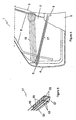
- each beam 88 is provided by two members 82 defining two cavities 83.
- An intermediate web section 84 consisting of a double sheet of material connects the members 82 and the members 82 are closed by a seam weld 87 extending between the longitudinal edges of the members 82.
- One end of each beam 88 is formed with a female part 85 and the other end of each beam 88 is formed with a male part 86.
- a longitudinal groove 81 is provided on opposite walls of each member 82.
- the beams 88 are stacked one on top of another to form a structural element.
Applications Claiming Priority (3)
| Application Number | Priority Date | Filing Date | Title |
|---|---|---|---|
| SE0102914A SE523371C2 (sv) | 2001-08-31 | 2001-08-31 | Balk |
| SE0102914 | 2001-08-31 | ||
| PCT/SE2002/001566 WO2003018338A1 (en) | 2001-08-31 | 2002-09-02 | A beam |
Publications (2)
| Publication Number | Publication Date |
|---|---|
| EP1420968A1 EP1420968A1 (en) | 2004-05-26 |
| EP1420968B1 true EP1420968B1 (en) | 2007-04-04 |
Family
ID=20285204
Family Applications (1)
| Application Number | Title | Priority Date | Filing Date |
|---|---|---|---|
| EP02768249A Expired - Lifetime EP1420968B1 (en) | 2001-08-31 | 2002-09-02 | A beam |
Country Status (7)
| Country | Link |
|---|---|
| US (1) | US7144072B2 (sv) |
| EP (1) | EP1420968B1 (sv) |
| JP (1) | JP4288162B2 (sv) |
| AT (1) | ATE358605T1 (sv) |
| DE (1) | DE60219327T2 (sv) |
| SE (1) | SE523371C2 (sv) |
| WO (1) | WO2003018338A1 (sv) |
Cited By (1)
| Publication number | Priority date | Publication date | Assignee | Title |
|---|---|---|---|---|
| US11027600B2 (en) | 2014-09-22 | 2021-06-08 | Arcelormittal | Reinforcement element for a vehicle, method for producing the same and door assembly |
Families Citing this family (25)
| Publication number | Priority date | Publication date | Assignee | Title |
|---|---|---|---|---|
| WO2004110850A2 (de) * | 2003-06-11 | 2004-12-23 | Brose Fahrzeugteile Gmbh & Co. Kg, Coburg | Verfahren zur herstellung einer kraftfahrzeugtür |
| JP4388340B2 (ja) | 2003-10-03 | 2009-12-24 | 新日本製鐵株式会社 | 自動車用強度部材 |
| US7585017B2 (en) * | 2005-05-10 | 2009-09-08 | Noble Advanced Technologies, Inc. | One-piece, tubular member with an integrated welded flange and associated method for producing |
| US20070222256A1 (en) * | 2006-03-23 | 2007-09-27 | Jeffrey Valentage | Hybrid door core and trim module with integrated components |
| BRPI0712529B1 (pt) * | 2006-05-11 | 2019-01-15 | Magna Closures Inc | conjunto de porta para um veículo motor e painel interno para um conjunto de porta |
| JP4240064B2 (ja) * | 2006-06-09 | 2009-03-18 | トヨタ自動車株式会社 | 車両用ドア構造 |
| US20080072428A1 (en) * | 2006-09-15 | 2008-03-27 | Hirotec Corporation | Method and system for manufacturing vehicle lid body |
| DE102007034313A1 (de) * | 2007-07-24 | 2009-01-29 | Lisa Dräxlmaier GmbH | Energieabsorber zur Verwendung als Aufprallschutz in einem Kraftfahrzeug |
| DE102007057855B3 (de) | 2007-11-29 | 2008-10-30 | Benteler Automobiltechnik Gmbh | Verfahren zur Herstellung eines Formbauteils mit mindestens zwei Gefügebereichen unterschiedlicher Duktilität |
| WO2009126617A1 (en) * | 2008-04-10 | 2009-10-15 | Noble Advanced Technologies, Inc. | Energy absorbing beam with controlled crush characteristics |
| DE102009011378B4 (de) * | 2009-03-05 | 2012-03-22 | Benteler Automobiltechnik Gmbh | Türaufprallträger |
| RU2495763C2 (ru) * | 2011-11-02 | 2013-10-20 | Общество с ограниченной ответственностью "Мобиль" | Способ изготовления бруса безопасности легкового автомобиля |
| US8979161B2 (en) * | 2013-03-15 | 2015-03-17 | GM Global Technology Operations LLC | Low mass truck end gate utilizing aluminum stampings and extrusions |
| JP5997836B2 (ja) * | 2013-04-03 | 2016-09-28 | 本田技研工業株式会社 | 車両用ドア |
| CN103559354A (zh) * | 2013-11-08 | 2014-02-05 | 吉林大学 | 汽车车身薄壁曲梁碰撞弯曲的简化分析方法 |
| WO2015081507A1 (en) * | 2013-12-04 | 2015-06-11 | GM Global Technology Operations LLC | Inner vehicle door panel including impact beam |
| CN103738279B (zh) * | 2013-12-24 | 2017-03-01 | 湖南湖大三佳车辆技术装备有限公司 | 一种轿车车门防撞梁 |
| JP6170895B2 (ja) * | 2014-10-22 | 2017-07-26 | 株式会社神戸製鋼所 | 自動車用耐衝突部品 |
| WO2016168588A1 (en) * | 2015-04-17 | 2016-10-20 | Shape Corp. | Impact beam for vehicle side door intrusion resistance |
| CN104943753A (zh) * | 2015-06-30 | 2015-09-30 | 宝山钢铁股份有限公司 | 一种变厚度汽车门槛梁及其制造方法 |
| DE102016112344A1 (de) * | 2016-07-06 | 2018-01-11 | Benteler Automobiltechnik Gmbh | Verstärkungsvorrichtung für eine Kraftfahrzeugtür |
| RU2715603C1 (ru) * | 2016-07-28 | 2020-03-02 | Ниппон Стил Корпорейшн | Внешняя панель транспортного средства |
| CN109229210B (zh) * | 2018-09-26 | 2024-03-22 | 凌云工业股份有限公司汽车零部件研发分公司 | 一种具有高抗弯性能的汽车横梁及加工方法 |
| DE102020115900A1 (de) | 2020-06-17 | 2021-12-23 | Audi Aktiengesellschaft | Versteifungsprofil für eine Fahrzeugtüre eines Fahrzeugs sowie Fahrzeugtüre mit einem Versteifungsprofil |
| DE102020116065A1 (de) * | 2020-06-18 | 2021-04-22 | Audi Aktiengesellschaft | Verstärkungsprofil, insbesondere Schachtverstärkung für einen als Türblech ausgebildeten Grundträger einer Fahrzeugkarosserie sowie Fahrzeugtüre mit einer solchen Schachtverstärkung |
Family Cites Families (13)
| Publication number | Priority date | Publication date | Assignee | Title |
|---|---|---|---|---|
| US3905630A (en) * | 1974-02-11 | 1975-09-16 | Houdaille Industries Inc | Lightweight, low cost impact resistant bumpers |
| GB2101535A (en) | 1981-05-12 | 1983-01-19 | Bl Tech Ltd | Vehicle door |
| SE434245B (sv) | 1982-02-01 | 1984-07-16 | Dobel Ab | Skyddsbalk, samt forfarande for dess framstellning |
| NO168517C (no) | 1990-01-09 | 1992-03-04 | Norsk Hydro As | Bjelke. |
| US5222564A (en) * | 1991-11-06 | 1993-06-29 | Boa Drilling Equipment Inc. | Drilling unit |
| DE4224303A1 (de) | 1992-07-23 | 1994-01-27 | Albert Griesemer | Verstärkungselement für Seitenwände von Automobilen sowie Verfahren zur Herstellung derartiger Verstärkungselemente |
| DE4421934A1 (de) | 1994-06-23 | 1996-01-04 | Ford Werke Ag | Metallisches Profil als Verstärkung einer Kraftfahrzeugtür |
| DE19525347C1 (de) | 1995-07-12 | 1996-07-11 | Ymos Ag Ind Produkte | Leistenförmiges Strukturbauteil und Verfahren zu seiner Herstellung |
| KR100206023B1 (en) * | 1997-04-10 | 1999-07-01 | Hyundai Motor Co Ltd | Method of roll-forming an automotive bumper |
| DE19748970B4 (de) | 1997-11-06 | 2005-12-08 | Ford Global Technologies, LLC (n.d.Ges.d. Staates Delaware), Dearborn | Integrale Türinnenverstärkung |
| SE514615C2 (sv) | 1998-09-22 | 2001-03-19 | Rolf Nystroem | Bjälklagsbalk |
| NO985846L (no) | 1998-12-14 | 2000-06-15 | Norsk Hydro As | FremgangsmÕte ved fremstilling av elementer |
| SE516762C2 (sv) | 1999-12-14 | 2002-02-26 | Accra Teknik Ab | Stötfångarbalk och förfarande vid tillverkning av densamma |
-
2001
- 2001-08-31 SE SE0102914A patent/SE523371C2/sv not_active IP Right Cessation
-
2002
- 2002-09-02 WO PCT/SE2002/001566 patent/WO2003018338A1/en active IP Right Grant
- 2002-09-02 US US10/486,980 patent/US7144072B2/en not_active Expired - Lifetime
- 2002-09-02 JP JP2003522826A patent/JP4288162B2/ja not_active Expired - Fee Related
- 2002-09-02 EP EP02768249A patent/EP1420968B1/en not_active Expired - Lifetime
- 2002-09-02 AT AT02768249T patent/ATE358605T1/de not_active IP Right Cessation
- 2002-09-02 DE DE60219327T patent/DE60219327T2/de not_active Expired - Lifetime
Cited By (1)
| Publication number | Priority date | Publication date | Assignee | Title |
|---|---|---|---|---|
| US11027600B2 (en) | 2014-09-22 | 2021-06-08 | Arcelormittal | Reinforcement element for a vehicle, method for producing the same and door assembly |
Also Published As
| Publication number | Publication date |
|---|---|
| JP4288162B2 (ja) | 2009-07-01 |
| SE0102914L (sv) | 2003-03-01 |
| SE0102914D0 (sv) | 2001-08-31 |
| US20050225115A1 (en) | 2005-10-13 |
| DE60219327D1 (de) | 2007-05-16 |
| US7144072B2 (en) | 2006-12-05 |
| SE523371C2 (sv) | 2004-04-13 |
| DE60219327T2 (de) | 2008-01-03 |
| EP1420968A1 (en) | 2004-05-26 |
| ATE358605T1 (de) | 2007-04-15 |
| WO2003018338A1 (en) | 2003-03-06 |
| JP2005500933A (ja) | 2005-01-13 |
Similar Documents
| Publication | Publication Date | Title |
|---|---|---|
| EP1420968B1 (en) | A beam | |
| EP2509849B2 (en) | B-pillar for a vehicle | |
| US6082811A (en) | Reinforcement for vehicle hollow structural member, having decreasing-thickness end portions | |
| US6726259B2 (en) | Method of making a steel crossbeam which crossbeam forms a component of a bumper for motor vehicles, and crossbeam | |
| US9216767B2 (en) | Front axle mounting with crash grooves | |
| JP4636799B2 (ja) | 自動車用の中空鋼長尺断面材製支持構造 | |
| JP4993142B2 (ja) | 一体化溶接フランジを有するワンピース管状部材およびそれを製造するための関連した方法 | |
| CN101977786B (zh) | 车门构造体及其制造方法 | |
| US20130140851A1 (en) | B-Pillar Reinforcement of a Motor Vehicle | |
| US6517142B2 (en) | Side impact support | |
| JP2005532207A5 (sv) | ||
| CN102529859A (zh) | 汽车保险杠横梁及其增强构件和保险杠横梁的制造方法 | |
| CN109789897B (zh) | 用于机动车辆车体的结构部件 | |
| US4750779A (en) | Vehicle with a cabin encasement with internal reinforcing elements | |
| JP2004051065A (ja) | 車体構造材および耐衝突補強材 | |
| JP2007055414A (ja) | 車両用エネルギ吸収ビーム及び車両用ドア構造 | |
| EP2113423B1 (en) | Bumper system for vehicle | |
| JP5243872B2 (ja) | 自動車サイドドアの下部構造 | |
| JP2003285703A (ja) | ステイ付きバンパー補強材 |
Legal Events
| Date | Code | Title | Description |
|---|---|---|---|
| PUAI | Public reference made under article 153(3) epc to a published international application that has entered the european phase |
Free format text: ORIGINAL CODE: 0009012 |
|
| 17P | Request for examination filed |
Effective date: 20040216 |
|
| AK | Designated contracting states |
Kind code of ref document: A1 Designated state(s): AT BE BG CH CY CZ DE DK EE ES FI FR GB GR IE IT LI LU MC NL PT SE SK TR |
|
| AX | Request for extension of the european patent |
Extension state: AL LT LV MK RO SI |
|
| GRAP | Despatch of communication of intention to grant a patent |
Free format text: ORIGINAL CODE: EPIDOSNIGR1 |
|
| GRAS | Grant fee paid |
Free format text: ORIGINAL CODE: EPIDOSNIGR3 |
|
| GRAA | (expected) grant |
Free format text: ORIGINAL CODE: 0009210 |
|
| AK | Designated contracting states |
Kind code of ref document: B1 Designated state(s): AT BE BG CH CY CZ DE DK EE ES FI FR GB GR IE IT LI LU MC NL PT SE SK TR |
|
| PG25 | Lapsed in a contracting state [announced via postgrant information from national office to epo] |
Ref country code: CH Free format text: LAPSE BECAUSE OF FAILURE TO SUBMIT A TRANSLATION OF THE DESCRIPTION OR TO PAY THE FEE WITHIN THE PRESCRIBED TIME-LIMIT Effective date: 20070404 Ref country code: FI Free format text: LAPSE BECAUSE OF FAILURE TO SUBMIT A TRANSLATION OF THE DESCRIPTION OR TO PAY THE FEE WITHIN THE PRESCRIBED TIME-LIMIT Effective date: 20070404 Ref country code: LI Free format text: LAPSE BECAUSE OF FAILURE TO SUBMIT A TRANSLATION OF THE DESCRIPTION OR TO PAY THE FEE WITHIN THE PRESCRIBED TIME-LIMIT Effective date: 20070404 |
|
| REG | Reference to a national code |
Ref country code: GB Ref legal event code: FG4D |
|
| REG | Reference to a national code |
Ref country code: CH Ref legal event code: EP |
|
| REF | Corresponds to: |
Ref document number: 60219327 Country of ref document: DE Date of ref document: 20070516 Kind code of ref document: P |
|
| REG | Reference to a national code |
Ref country code: IE Ref legal event code: FG4D |
|
| PG25 | Lapsed in a contracting state [announced via postgrant information from national office to epo] |
Ref country code: SE Free format text: LAPSE BECAUSE OF FAILURE TO SUBMIT A TRANSLATION OF THE DESCRIPTION OR TO PAY THE FEE WITHIN THE PRESCRIBED TIME-LIMIT Effective date: 20070704 |
|
| PG25 | Lapsed in a contracting state [announced via postgrant information from national office to epo] |
Ref country code: ES Free format text: LAPSE BECAUSE OF FAILURE TO SUBMIT A TRANSLATION OF THE DESCRIPTION OR TO PAY THE FEE WITHIN THE PRESCRIBED TIME-LIMIT Effective date: 20070715 |
|
| PG25 | Lapsed in a contracting state [announced via postgrant information from national office to epo] |
Ref country code: PT Free format text: LAPSE BECAUSE OF FAILURE TO SUBMIT A TRANSLATION OF THE DESCRIPTION OR TO PAY THE FEE WITHIN THE PRESCRIBED TIME-LIMIT Effective date: 20070904 |
|
| NLV1 | Nl: lapsed or annulled due to failure to fulfill the requirements of art. 29p and 29m of the patents act | ||
| REG | Reference to a national code |
Ref country code: CH Ref legal event code: PL |
|
| PG25 | Lapsed in a contracting state [announced via postgrant information from national office to epo] |
Ref country code: AT Free format text: LAPSE BECAUSE OF FAILURE TO SUBMIT A TRANSLATION OF THE DESCRIPTION OR TO PAY THE FEE WITHIN THE PRESCRIBED TIME-LIMIT Effective date: 20070404 |
|
| PG25 | Lapsed in a contracting state [announced via postgrant information from national office to epo] |
Ref country code: BE Free format text: LAPSE BECAUSE OF FAILURE TO SUBMIT A TRANSLATION OF THE DESCRIPTION OR TO PAY THE FEE WITHIN THE PRESCRIBED TIME-LIMIT Effective date: 20070404 |
|
| PG25 | Lapsed in a contracting state [announced via postgrant information from national office to epo] |
Ref country code: DK Free format text: LAPSE BECAUSE OF FAILURE TO SUBMIT A TRANSLATION OF THE DESCRIPTION OR TO PAY THE FEE WITHIN THE PRESCRIBED TIME-LIMIT Effective date: 20070404 Ref country code: CZ Free format text: LAPSE BECAUSE OF FAILURE TO SUBMIT A TRANSLATION OF THE DESCRIPTION OR TO PAY THE FEE WITHIN THE PRESCRIBED TIME-LIMIT Effective date: 20070404 Ref country code: NL Free format text: LAPSE BECAUSE OF FAILURE TO SUBMIT A TRANSLATION OF THE DESCRIPTION OR TO PAY THE FEE WITHIN THE PRESCRIBED TIME-LIMIT Effective date: 20070404 Ref country code: BG Free format text: LAPSE BECAUSE OF FAILURE TO SUBMIT A TRANSLATION OF THE DESCRIPTION OR TO PAY THE FEE WITHIN THE PRESCRIBED TIME-LIMIT Effective date: 20070704 |
|
| PLBE | No opposition filed within time limit |
Free format text: ORIGINAL CODE: 0009261 |
|
| STAA | Information on the status of an ep patent application or granted ep patent |
Free format text: STATUS: NO OPPOSITION FILED WITHIN TIME LIMIT |
|
| PG25 | Lapsed in a contracting state [announced via postgrant information from national office to epo] |
Ref country code: SK Free format text: LAPSE BECAUSE OF FAILURE TO SUBMIT A TRANSLATION OF THE DESCRIPTION OR TO PAY THE FEE WITHIN THE PRESCRIBED TIME-LIMIT Effective date: 20070404 |
|
| 26N | No opposition filed |
Effective date: 20080107 |
|
| PG25 | Lapsed in a contracting state [announced via postgrant information from national office to epo] |
Ref country code: MC Free format text: LAPSE BECAUSE OF NON-PAYMENT OF DUE FEES Effective date: 20070930 Ref country code: IT Free format text: LAPSE BECAUSE OF FAILURE TO SUBMIT A TRANSLATION OF THE DESCRIPTION OR TO PAY THE FEE WITHIN THE PRESCRIBED TIME-LIMIT Effective date: 20070404 Ref country code: GR Free format text: LAPSE BECAUSE OF FAILURE TO SUBMIT A TRANSLATION OF THE DESCRIPTION OR TO PAY THE FEE WITHIN THE PRESCRIBED TIME-LIMIT Effective date: 20070705 |
|
| PG25 | Lapsed in a contracting state [announced via postgrant information from national office to epo] |
Ref country code: IE Free format text: LAPSE BECAUSE OF NON-PAYMENT OF DUE FEES Effective date: 20070903 |
|
| PG25 | Lapsed in a contracting state [announced via postgrant information from national office to epo] |
Ref country code: EE Free format text: LAPSE BECAUSE OF FAILURE TO SUBMIT A TRANSLATION OF THE DESCRIPTION OR TO PAY THE FEE WITHIN THE PRESCRIBED TIME-LIMIT Effective date: 20070404 |
|
| PG25 | Lapsed in a contracting state [announced via postgrant information from national office to epo] |
Ref country code: CY Free format text: LAPSE BECAUSE OF FAILURE TO SUBMIT A TRANSLATION OF THE DESCRIPTION OR TO PAY THE FEE WITHIN THE PRESCRIBED TIME-LIMIT Effective date: 20070404 |
|
| PG25 | Lapsed in a contracting state [announced via postgrant information from national office to epo] |
Ref country code: LU Free format text: LAPSE BECAUSE OF NON-PAYMENT OF DUE FEES Effective date: 20070902 |
|
| PG25 | Lapsed in a contracting state [announced via postgrant information from national office to epo] |
Ref country code: TR Free format text: LAPSE BECAUSE OF FAILURE TO SUBMIT A TRANSLATION OF THE DESCRIPTION OR TO PAY THE FEE WITHIN THE PRESCRIBED TIME-LIMIT Effective date: 20070404 |
|
| PGFP | Annual fee paid to national office [announced via postgrant information from national office to epo] |
Ref country code: DE Payment date: 20140930 Year of fee payment: 13 |
|
| PGFP | Annual fee paid to national office [announced via postgrant information from national office to epo] |
Ref country code: FR Payment date: 20140919 Year of fee payment: 13 Ref country code: GB Payment date: 20140919 Year of fee payment: 13 |
|
| REG | Reference to a national code |
Representative=s name: DR. MUELLER PATENTANWAELTE, DE Ref country code: DE Ref legal event code: R082 Ref document number: 60219327 Country of ref document: DE |
|
| REG | Reference to a national code |
Ref country code: DE Ref legal event code: R082 Ref document number: 60219327 Country of ref document: DE Representative=s name: DR. MUELLER PATENTANWAELTE, DE |
|
| REG | Reference to a national code |
Ref country code: DE Ref legal event code: R119 Ref document number: 60219327 Country of ref document: DE |
|
| GBPC | Gb: european patent ceased through non-payment of renewal fee |
Effective date: 20150902 |
|
| REG | Reference to a national code |
Ref country code: FR Ref legal event code: ST Effective date: 20160531 |
|
| PG25 | Lapsed in a contracting state [announced via postgrant information from national office to epo] |
Ref country code: DE Free format text: LAPSE BECAUSE OF NON-PAYMENT OF DUE FEES Effective date: 20160401 Ref country code: GB Free format text: LAPSE BECAUSE OF NON-PAYMENT OF DUE FEES Effective date: 20150902 |
|
| PG25 | Lapsed in a contracting state [announced via postgrant information from national office to epo] |
Ref country code: FR Free format text: LAPSE BECAUSE OF NON-PAYMENT OF DUE FEES Effective date: 20150930 |