EP1420521A2 - System und Verfahren zur Kanaldiagnose - Google Patents
System und Verfahren zur Kanaldiagnose Download PDFInfo
- Publication number
- EP1420521A2 EP1420521A2 EP03016209A EP03016209A EP1420521A2 EP 1420521 A2 EP1420521 A2 EP 1420521A2 EP 03016209 A EP03016209 A EP 03016209A EP 03016209 A EP03016209 A EP 03016209A EP 1420521 A2 EP1420521 A2 EP 1420521A2
- Authority
- EP
- European Patent Office
- Prior art keywords
- filter
- channel
- filter coefficients
- thresholds
- determining
- Prior art date
- Legal status (The legal status is an assumption and is not a legal conclusion. Google has not performed a legal analysis and makes no representation as to the accuracy of the status listed.)
- Withdrawn
Links
Images


Classifications
-
- H—ELECTRICITY
- H04—ELECTRIC COMMUNICATION TECHNIQUE
- H04L—TRANSMISSION OF DIGITAL INFORMATION, e.g. TELEGRAPHIC COMMUNICATION
- H04L25/00—Baseband systems
- H04L25/02—Details ; arrangements for supplying electrical power along data transmission lines
- H04L25/03—Shaping networks in transmitter or receiver, e.g. adaptive shaping networks
- H04L25/03878—Line equalisers; line build-out devices
- H04L25/03885—Line equalisers; line build-out devices adaptive
-
- H—ELECTRICITY
- H04—ELECTRIC COMMUNICATION TECHNIQUE
- H04L—TRANSMISSION OF DIGITAL INFORMATION, e.g. TELEGRAPHIC COMMUNICATION
- H04L1/00—Arrangements for detecting or preventing errors in the information received
- H04L1/24—Testing correct operation
-
- H—ELECTRICITY
- H04—ELECTRIC COMMUNICATION TECHNIQUE
- H04L—TRANSMISSION OF DIGITAL INFORMATION, e.g. TELEGRAPHIC COMMUNICATION
- H04L25/00—Baseband systems
- H04L25/02—Details ; arrangements for supplying electrical power along data transmission lines
- H04L25/0202—Channel estimation
Definitions
- the present invention relates generally to communication devices and related methods, and more particularly, to such a device using an adaptive filter.
- a known communication system includes a pair of transceivers that communicate with each other over a communication channel, such as a wire or optical cable.
- a fault in the communication channel inhibits communication between the transceivers. It is desirable to be able to determine whether such a fault exists. If such a channel fault exists, it may be difficult to determine useful information about the fault upon basic inspection, such as its location in the channel. Thus, it is also desirable to be able to determine information about the fault, such as its location in the channel. It is also desirable to be able to determine other information about the communication channel, such as the length of the channel in the absence of a fault. It is also desirable to be able to determine the above-mentioned information about the channel without having to examine the channel physically.
- a known receiver includes an analog-to-digital converter (ADC) for sampling a receive signal in accordance with a sample clock having a sample clock phase, to produce a digitized receive signal.
- ADC analog-to-digital converter
- An adaptive filter in a demodulator following the ADC, adaptively filters the digitized signal.
- the sample clock phase affects the performance of the adaptive filter. Therefore, it is desirable to set the sample clock phase to a phase value that maximizes performance.
- Embodiments of the present invention include systems and related methods for determining information about a communication channel.
- the system includes an adaptive filter coupled to the communication channel.
- the adaptive filter includes a set of adaptive filter coefficients.
- a memory stores a predetermined set of filter coefficient thresholds for comparison against the filter coefficients.
- the filter coefficient thresholds may be indicative of channel faults or a length of the channel, for example.
- a controller is configured to compare the set of filter coefficients to the predetermined set of filter coefficient thresholds.
- the controller is configured to determine the information about the channel based on compare results from the compare step.
- the information about the channel includes (i) whether there is a channel fault, such as an open or short circuit condition in the channel, and (ii) if there is a channel fault, a distance between the adaptive filter and the fault, and (iii) a length of the channel in the case where there is no channel fault.
- a channel fault such as an open or short circuit condition in the channel
- a method of selecting a best sampling phase to be used in the apparatus comprising:
- the filter coefficient thresholds include different thresholds
- step (c) comprises comparing each of the converged filter coefficients to a corresponding one of the different thresholds.
- step (b) comprises:
- an apparatus configured to process a received signal, comprising:
- the controller further includes:
- the filter coefficient thresholds include different thresholds.
- the different filter coefficient thresholds have stepped values.
- the compare module is configured to compare each filter coefficient of the converged filter coefficients to a corresponding one of the different thresholds.
- the adaptive filter includes at least one of an adaptive echo canceller and an adaptive equalizer.
- FIG. 1 is a block diagram of an example communication system in which the present invention can operate.
- FIG. 2 is a block diagram of an example system, constructed and operated in accordance with the principles of the present invention, which expands on a transceiver of FIG. 1.
- FIG. 3 is a block diagram of an example arrangement of an adaptive filter of FIG. 2.
- FIG. 4 is a block diagram of an example arrangement of a post filter stage of FIG. 2.
- FIG. 5 is a flowchart of an example method of determining information about a channel based on filter coefficients and corresponding filter coefficient thresholds.
- FIG. 5A is a flowchart of an alternative method related to the method of FIG. 5.
- FIG. 6 is a flowchart of another example method of determining information about a communication channel.
- FIG. 7 is a flowchart further expanding on the method of FIG. 6.
- FIG. 7A is a block diagram of a diagnostic module in a controller of the transceiver of FIG. 2.
- FIG. 8 is a flowchart of an example method of fine-tuning a received signal sampling phase in a transceiver based on filter coefficients.
- FIG. 9 is a block diagram of an example arrangement of a controller module used to implement portions of the method of FIG. 8.
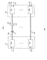
- FIG. 1 is an example communication system 100 in which the present invention can operate.
- System or environment 100 includes a transmitter/receiver (transceiver) assembly 102 and a transceiver assembly 104, that communicate with each other over communication channels 106a-106n.
- Transceiver assembly 102 includes transceivers 108a-108n, coupled respectively to communication channels 106a-106n.
- Transceiver assembly 104 includes transceivers 110a-110n respectively coupled to communication channels 106a-106n.
- Communication channels 106 may include wire and/or optical cables.
- the terms "channel” and “cable” are used equivalently and interchangeably herein.
- transceiver 108a receives an input symbol stream 112T from an external data source, not shown.
- Transceiver 108a generates a transmit symbol stream or signal 114T from input symbol stream 112T, and transmits the symbol stream to corresponding transceiver 110a over communication channel 106a.
- Transceivers 108a and 110a are said to be communication "link partners,” because they establish a communication link between, and then communicate with, each other over communication channel 106a.
- Transceiver 108a receives a receive signal 114R from communication channel 106a.
- Receive signal 114R may include a transmit signal originated from transceiver 110a. Additionally and/or alternatively, receive signal 114R represents energy from transmit signal 114T that has been reflected back toward transceiver 108a. Transmit signal 114T may be reflected from a channel fault 116 in channel 106a (such as a break in the channel) and/or from an impedance mismatch at a coupling section between channel 106a and transceiver assembly 104. Such reflected energy represents an "echo.”
- Transceiver 108a receives symbol stream 114R, and derives a corrected, adaptively filtered output stream 118R from symbol stream 114R.
- FIG. 2 is a block diagram of an example arrangement of transceiver 108a.
- Transceiver 108a includes a transmit path 202, a line interface 204, a receive path 206, a controller module 208, and a receive sample clock generator 210.
- Transmit path 202 includes a modulator 214 and a transmit amplifier 216. Together, modulator 214 and transmit amplifier 216 generate transmit symbol stream or signal 114T from input symbol stream 112T.
- Line interface 204 couples transmit signal 114T to communication channel 106a.
- transmit path 202 provides a signal 217 representative of transmit symbol stream 114T to receive path 206.
- Signal 217 may be a digital signal or an analog signal representation of transmit signal 114T.
- Line interface 204 couples receive signal 114R to receive path 206.
- Receive path 206 includes a variable gain amplifier 224, an analog-to-digital converter (ADC) 226, and a demodulator 228, connected in series.
- Amplifier 224 amplifies signal 222R, and provides an amplified receive signal 230 to ADC 226.
- ADC 226 samples signal 230 in accordance with an ADC sample clock 229, generated by sample clock generator 210, to produce a digitized receive signal 232.
- ADC 226 provides signal 232 to demodulator 228.
- Demodulator 228 includes an adaptive filter 234 followed by a post-filtering stage 238.
- Demodulator 228 and adaptive filter 234 receive transmit replica signal 217 from transmit path 202.
- adaptive filter 234 is coupled to communication channel 106a through components 204, 224 and 226.
- other arrangements for coupling the adaptive filter to the communication channel are possible, as would be apparent to one of ordinary skill in the relevant arts) given the present description.
- Adaptive filter 234 generally represents any number of adaptive signal processors including, but not limited to, an echo canceler and an equalizer.
- adaptive filter 234 includes an adaptive echo canceler that uses transmit replica signal 217 to subtract-out echoes included in receive signal 114R.
- adaptive filter 234 includes an adaptive equalizer that equalizes receive signal 114R.
- Adaptive filter 234 may operate as both an equalizer and an echo canceler, and may also provide adaptive filtering in addition to echo canceling and equalization.
- adaptive filter 234 may include at least one of an adaptive echo canceler and an adaptive equalizer. Further details regarding the operation of such signal processing elements are provided in copending U.S. Non-Provisional Application No.
- Adaptive filter 234 processes signal 232, in accordance with a set of adaptive filter coefficients 236 produced by the filter, to produce a processed (e.g., adaptively filtered) receive signal 240.
- Adaptive filter coefficients 236 generally represent adaptive filter, adaptive echo canceler, and/or adaptive equalizer coefficients, whereby adaptive filter 234 adaptively filters, adaptively echo cancels, and/or adaptively equalizes signal 232, respectively.
- Post-filtering stage 238 further processes signal 240 to produce corrected, adaptively filtered output stream 118R.
- Post-filtering stage 238 also derives a feedback error signal 244, and provides the error signal to adaptive filter 234.
- Controller module 208 controls transceiver 108a.
- Controller module 208 includes controller logic 246, a memory 248 for storing a polynomial constant database, and a memory 250 for storing a threshold database.
- Controller logic 246 includes a channel diagnostic module 252 and a phase tuner and timing recovery module 254.
- the polynomial constant database stored in memory 248 includes a first set of polynomial constants 256 indicative of channel faults, and a second set of polynomial constants 258 indicative of channel length.
- the threshold database stored in memory 250 includes a first set of thresholds 260 indicative of channel faults, and a second set of thresholds 262 indicative of channel length.
- Controller logic 246 accesses the polynomial constant database stored in memory 248 and the threshold database stored in memory 250 as needed by channel diagnostic module 252 in order to execute methods of the present invention.
- Controller logic 246 controls adaptive filter 234 through an interface 264.
- controller 208 issues commands to filter 234, and accesses filter coefficients 236 through interface 264.
- Controller 208 stores filter coefficients in a controller memory 270.
- Transceiver 108a includes a user interface 268 that supports user interaction with the transceiver through input/output (I/O) operations.
- I/O input/output
- a user may program databases memories 248 and 250 through interface 268, and controller 208 may report test results to the user through the interface.
- Controller 208 also controls sample clock generator 210 over an interface 270. For example, controller 208 issues sampling phase commands to generator 210 over interface 270. In turn, generator 210 generates sample clock 229 at sampling phases in accordance with the sampling phase commands. ADC 226 samples signal 230 in accordance with the sampling phases of clock 229 to produce sampled signal 232.
- Controller 208 also controls the gain of variable gain amplifier 224.
- FIG. 3 is a block diagram of an example arrangement of adaptive filter 234.
- Adaptive filter 234 includes a series of time delay elements 302, a set of signal taps 304 coupled to delay elements 302, a set of multipliers 306 coupled to taps 304, an adaptive coefficient adjustment module 308, and a summer 310.
- Time delay elements 302 1 - 302 n successively delay digitized receive signal 232 and feed taps 304 1 to 304 n (where subscripts 1-n indicate tap numbers) with successively delayed representations or portions of signal 232. As depicted in FIG.
- non-delayed signal 232 feeds tap 304 0 directly, while successively delayed representations or portions of signal 232 produced by delay elements 302 1 - 302 n feed respective taps 304 1 - 304 n .
- Each tap 304 0 - 304 n feeds a respective one of multipliers 306 0 - 306 n .
- an increase in tap number corresponds to an increase in time delay in filter 234.
- Module 308 generates adaptive filter coefficients 236 (labeled in FIG. 3 as filter coefficients C 0 - C n ) based on feedback error signal 244, and provides each of the coefficients to a respective one of multipliers 306 0 -306 n , as depicted in FIG. 3.
- Multipliers 306 0 - 306 n produce product signals 312 0 - 312 n based on filter coefficients C 0 - C n and the respective successively delayed signals associated with taps 304 0 - 304 n .
- Summer 310 sums product signals 312 0 - 312 n to produce processed signal 240.
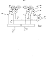
- FIG. 4 is a block diagram of an example arrangement of post-filtering stage 238.
- a signal summer 402 sums processed signal 240 with signals 408 from other filters (not shown) to produce a "soft decision" signal 410.
- soft decision it is meant that signal 410 may take on a range of different values, instead of just one of two logic values (for example, logic “1” and logic “0").
- signals 408 are omitted.
- a slicer 404 processes soft decision signal 410 to produce corrected output stream 118R, including a stream of "hard decisions” (such as logic "1s and logic "0s". Corrected output stream 118R includes hard decisions made by slicer 404.
- a comparator 406 compares soft decision signal 410 to corrected output stream 118R to produce feedback error signal 244.
- the adaptive filter (for example, filter 234) reverses the negative effects of a noisy and distortive transmission medium (such as channel 106a).
- the output of the filter (for example, signal 240 or signal 118R) is a best-guess estimate of the symbol stream the link partner's transmitter sends (for example, the symbol stream transmitted by the transmitter in remote transceiver 110a).
- the filter includes a series of multiply-and-add stages (for example, components 306 and 310) that operate on the received data stream (for example, signal 232).
- Each multiplier (for example, multiplier 306 i ) has an associated filter coefficient (for example, filter coefficient C i ) that adapts itself to the characteristics of the received data stream such that the filter reverses the noise and distortion effects of the channel.
- filter coefficients adapt to channel conditions, and when interpreted properly, provide valuable information about the channel.
- cable faults including a severed connection or "open circuit," and a fused connection or “short circuit”
- filter coefficient fault thresholds that set a limit on reasonable values of the filter coefficients corresponding to non-fault channel conditions.
- An abnormally enlarged filter coefficient that exceeds one such predetermined threshold indicates a fault in the channel.
- a good approximation of the distance between the filter (in the transceiver) and such an indicated channel fault can be calculated based on the tap number corresponding to the enlarged coefficient.
- a good approximation of the channel length can be determined by comparing the filter coefficients to a different set of predetermined thresholds indicative of channel length when no channel fault exists, and finding the tap number of any coefficient that exceeds one of these thresholds.
- the filter coefficients exceed the above mentioned thresholds for the following reason.
- Channel faults and similarly, the coupling between the end of the channel and the remote transceiver or link partner
- the fault or channel-end coupling
- the adaptive filter attempts to remove the effects of the reflections or echoes by enlarging some of the filter coefficients.
- the longer the distance between the transceiver (for example, transceiver 108a) and the channel fault the longer it takes for the reflection to return to the adaptive filter, and the larger the tap number(s) of the enlarged coefficients.
- the longer the distance between the transceiver and the channel fault or coupling the smaller the amplitude of the reflected signal, and the less the corresponding filter coefficient values are enlarged.
- the adaptive filter receives the transmitted signal from its associated transmitter, as the line interface initially couples the transmitted signal to the channel.
- the adaptive filter adjusts to the "timing" of the transmitted signal in the channel.
- Such timing of the transmitted signal is inherently represented by the adapted filter coefficients.
- FIG. 5 is a flowchart of an example method 500 of diagnosing one or more communication channels, such as channels 106a - 106n depicted in FIG. 1, based on filter coefficients and corresponding filter coefficient thresholds. That is, method 500 determines information about the communication channels.
- method 500 is described in the context of transceiver 108a. Method 500 may be implemented under control of controller 208 in the transceiver 108a.
- Method 500 includes a first step 502 ("idle"). Idle is the state where the method is at rest.
- transceivers 108a and 110a attempt to establish a valid communication link between themselves, to enable communication over the valid link (and communication channel 106a). To do this, transceivers 108a and 110a traverse a communication link setup protocol. Typically, this includes exchanging initial hand-shaking signals, and verifying a valid link has been established, as would be apparent to one of ordinary skill in the relevant art(s).
- filter coefficients C When a valid link exists, filter coefficients C 0 - C n (collectively referred to as filter coefficients C) have properly converged to settled coefficient values. That is, filter coefficients C have had sufficient time to adapt to, and therefore indicate, the characteristics and/or conditions of communication channel 106a. Thus, converged coefficients provide useful information about communication channel 106a,
- a valid link may not exist between link partner transceivers 108a and 110a
- filter coefficients C can be in an indeterminate (non-converged) state, thus provide little or no useful information about channel 106a.
- Method 500 overcomes or avoids indeterminate filter coefficients in a step 504 ("converge").
- controller 208 instructs adaptive filter 234, over interface 264, to converge filter coefficients C.
- adaptive filter 234 performs a convergence, and filter coefficients C adapt properly to characteristics of channel 106a.
- Step 504 includes initializing the filter coefficients C to initial values, and then permitting the initialized coefficients to settle to converged values based on the receive signal (e.g., signal 232), for example, while adaptive filter 234 performs filtering, echo canceling, and/or equalization. After convergence, converged filter coefficients C indicate useful information about channel 106a. Note that step 504 is an optional step.
- controller 208 accesses converged filter coefficients C and stores them in memory 270 of the controller.
- a next step 508 is a comparison step that is part of testing channel 106a for open or short channel fault conditions that may be caused, for example, by a break in the channel.
- This step includes comparing filter coefficients C to thresholds 260 indicative of channel faults (also referred to as open/short thresholds 260).
- step 508 includes comparing an absolute value of each of the filter coefficients C to a corresponding one of the open/short thresholds 260, sequentially beginning with the filter coefficient corresponding to the signal tap having the least amount of time delay (e.g., in the signal tap order 304 0 - 304 n ). This comparison searches for the first one of filter coefficients C that is found to exceed its corresponding one of the open/short thresholds 260. Such a filter coefficient would represent the existence of a fault. Processing the filter coefficients in an order of increasing tap number (i.e., time delay) identifies channel faults nearest transceiver 108a.
- tap number i.e., time delay
- a next step 510 (“open/short found?") is a decision step. If step 508 detected a filter coefficient among filter coefficients C that exceeded its corresponding one of the open/short thresholds 260, then a channel fault (e.g., channel fault 116 in channel 106a) is identified, and step 510 returns a "YES" signal. Method 500 then proceeds to a step 512 ("calculate and report results"). If step 508 did not detect a coefficient representing the existence of a channel fault, then step 510 returns a "NO” signal and method 500 proceeds to a step 514 ("valid channel length").
- a channel fault e.g., channel fault 116 in channel 106a
- Step 512 includes calculating a distance to the channel fault detected in step 508 and reporting the results over user interface 268.
- a and B are predetermined polynomial values in the first set of constants 256 indicative of channel faults
- t is the tap number corresponding to the coefficient that exceeds its corresponding one of the open/short thresholds 260
- length is the distance from the transceiver/adaptive filter to the channel fault (e.g. channel fault 116).
- the length can be reported over user interface 268.
- status flags may be set, such as status bits in a register associated with controller 208, indicating the fault process has completed and that a channel fault was found.
- Step 514 is a comparison step, wherein filter coefficients C are compared to thresholds 262 indicative of channel length (also referred to as length thresholds 262).
- Step 514 is similar to step 508, except that the thresholds used are length thresholds 262. Also, filter coefficients C are compared to corresponding ones of length thresholds 262 in a reverse order with respect to the order of comparison of step 508. That is, the filter coefficients C are traversed sequentially beginning with the coefficient corresponding to the signal tap having the most amount of time delay (e.g., in the signal tap order 304 n - 304 0 ). If a filter coefficient is found to exceed its corresponding one of the length thresholds 262, then such a coefficient would be useful for calculating channel length in a later step (step 519, discussed below).
- the thresholds used are length thresholds 262.
- filter coefficients C are compared to corresponding ones of length thresholds 262 in a reverse order with respect to the order of comparison of step 508. That is, the filter coefficients C are traversed sequentially beginning with the coefficient corresponding to the signal tap having the most amount of time delay (e.g., in the signal tap order 304 n - 304
- a next step 518 is a decision step. If step 514 detected a filter coefficient among filter coefficients C that exceeded its corresponding one of the length thresholds 262, then step 518 returns a "YES" signal. Method 500 then proceeds to a step 519 ("calculate length and report results”). If step 514 did not detect a coefficient useful for calculating length, then step 518 returns a "NO” signal and method 500 proceeds to a step 520 ("report error").
- C and D are predetermined polynomial values in the second set of constants 258 indicative of channel length
- t is the tap number
- length is the channel length (e.g. the length of channel 106a).
- the length can be reported to or accessed by a user through user interface 268.
- status flags may be set, such as bits in a register associated with controller 208, indicating that length has been determined and that no channel fault was found.
- Step 520 includes reporting an error to user interface 268 if no filter coefficient among filter coefficients C is found to exceed its corresponding one of the length thresholds 262
- Step 516 includes determining whether a further non-diagnosed channel exists. For example, if only channel 106a has been diagnosed, channels 106b - 106n are yet to be diagnosed. If a non-diagnosed channel exists, step 516 returns a "YES" signal and method 500 returns to step 506. If no non-diagnosed channel exists, step 516 returns a "NO" signal and flow returns to step 502.
- step 500 In the case of some Ethernet systems, for example, there are four wire pairs (that is, channels) connected to each transceiver, so method 500 continues to analyze the next three wire pairs in search of channel faults, until all four wire pairs (that is, channels) are completed. After all the channels are analyzed, flow returns to step 502.
- FIG. 5A is a flowchart of an alternate method 500A related to the beginning portion of method 500.
- This alternative method 500A is referred to as "the Natural Link" variation of method 500.
- Method 500A takes advantage of the fact that if a valid link has already been achieved, then filter coefficients C are guaranteed to be converged properly and thus information about the channel is readily available. Forcing a new convergence of the adaptive filter would not be beneficial, and could even result in a loss of receive data. Thus, the convergence step 504 may be skipped under such circumstances.
- a decision step 503 is inserted after idle step 502. If a valid communication link partner exists, step 503 returns a "YES” and flow skips to next step 506. That is, flow bypasses convergence step 504 of method 500. On the other hand, if a valid communication link partner does not exist, then step 503 returns a "NO" and flow continues to step 504.
- variable gain amplifier 224 When method 500A is enabled, the gain of variable gain amplifier 224 is maintained at a proper gain value, which in turn, decreases the absolute values of many of the filter coefficients C. In this case, a more uniform threshold can be applied to all the coefficients, instead of the stepped thresholds that are used for both the Open/Short and cable length comparisons/determinations discussed above.
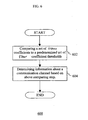
- FIG. 6 is a flowchart of another example method 600 of determining information about a communication channel.
- a first step 602 includes comparing the set of adaptive filter coefficients 236 to a predetermined set of filter coefficient thresholds, such as the first set of thresholds 260 indicative of fault, and/or the second set of thresholds 262 indicative of channel length. Step 602 corresponds to comparison step 508 or comparison step 514 of method 500.
- Step 604 includes determining information about the channel based on comparing step 602. Step 604 corresponds to determining steps 510 and 512 or determining steps 518 and 519 of method 500. According to method 600, determining (i) channel faults and distances thereto, and (ii) channel length, may be considered as independent methods.
- step 604 includes determining a filter coefficient corresponding to a minimum time delay (that is, corresponding to a lowest tap number) among filter coefficients that exceed their respective threshold. For example, if more than one enlarged filter coefficients among filter coefficients C exceed their respective thresholds indicative of channel faults, then step 604 determines fault information based on the enlarged filter coefficient corresponding to the lowest time delay (that is, lowest tap number) among the enlarged filter coefficients.
- step 604 includes determining a filter coefficient corresponding to a maximum time delay (that is, corresponding to a highest tap number) among filter coefficients that exceed their respective threshold. For example, if more than one enlarged filter coefficients among filter coefficients C exceed their respective thresholds indicative of channel length, then step 604 determines channel length based on the enlarged filter coefficient corresponding to the highest time delay (that is, highest tap number) among the enlarged filter coefficients.
- FIG. 7 is a flowchart expanding on step 604.
- a decisions step 702 includes determining whether a channel fault exists based on comparison step 602. If a channel fault exists, step 702 returns a "YES" signal, and flow proceeds to a step 704. If no channel fault exists, step 702 returns a "NO" signal, and flow proceeds to a step 706.
- Step 704 includes calculating a distance to the channel fault (and corresponds to step 512 in FIG. 5).
- Step 706 includes calculating a channel length (and corresponds to step 519 in FIG. 5).
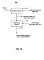
- FIG. 7A is a block diagram of an example arrangement of diagnostic module 252 of controller 208.
- Module 252 includes a compare module 750 coupled to a determining module 752.
- Compare module 750 includes comparing logic (such as one or more comparators) for comparing filter coefficients C to corresponding members of the coefficient threshold sets 256 and 258, in the manner described above. Compare module 750 produces compare results 756 based on these comparisons. Compare results 756 may include flags indicating which, if any, of the filter coefficients exceed their respective thresholds, for example.
- determining module 752 receives compare results 756, polynomial coefficients from databases 260 and 262, and tap numbers corresponding to filter coefficients C. Based on these inputs, determining module 752 can determine whether a channel fault exists, the distance to such a fault, or the channel length, in the manner described above. Determining module 752 produces these determinations as a results signal 760.
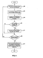
- FIG. 8 is a flowchart of an example method 800 of fine-tuning a received signal sampling phase in an individual transceiver, using a set of filter coefficients and a predetermined set of filter coefficient thresholds corresponding to the set of filter coefficients.
- Method 800 may be implemented in an apparatus, such as a receiver (for example, receive path 206), or more generally, a transceiver 108a, under the control of controller module 254.
- a step 802 includes producing a sampled signal using a candidate sampling phase.
- ADC 226 produces digitized signal 232 using a candidate sampling phase of sample clock 229.
- a next step 804 includes converging a set of filter coefficients based on the candidate sampling phase. For example, this may involve initializing the set of filter coefficients 236, then allowing the set of filter coefficients 236 to adapt to the sampled signal having the candidate sampling phase. For example, adaptive filter 234 converges filter coefficients C based on receive signal 232, in response to a converge command from controller 208.
- a next step 805 includes comparing each filter coefficient in the set of converged filter coefficients 236 to a corresponding filter coefficient threshold in the set of filter coefficient thresholds (e.g., thresholds 260), in a manner as discussed above, for example, as in methods 500 and 600.
- a next step 806 is a decision step.
- Step 806 includes determining if any of converged filter coefficients 236 exceed their corresponding coefficient thresholds (e.g., thresholds 260), as indicated at step 805.
- steps 805 and 806 comprise determining if any of converged filter coefficients 236 are excessive, that is, if they exceed their corresponding thresholds (e.g., thresholds 260).
- Controller 208 performs steps 805 and 806.
- Step 807 includes determining a largest excessive converged filter coefficient among the excessive converged filter coefficients 236 determined at steps 805 and 806. For example, controller 208 determines a largest one of the excessive converged filter coefficients. This largest excessive coefficient corresponds to the candidate sampling phase used in step 802 to produce signal 232. Steps 802-807 alone are considered an independent method of processing a received signal in a receiver.
- a next step 808 is a decision step. If there is an additional candidate sampling phase to be tested, step 808 returns a "YES" signal and flow returns to step 802. If all candidate sampling phases have been tested, then step 808 returns a "NO" signal and flow continues to a step 812.
- Step 812 includes selecting as the best sampling phase the candidate sampling phase corresponding to a largest one of the largest excessive converged filter coefficients.
- steps 802-807 taken alone may be considered an independent method of processing a received signal in a receiver.
- the further steps 808-812, and the repetition of steps 802-807 for different candidate sampling phases, are necessary to select a best sampling phase among a plurality of candidate sampling phases.
- Method 800 selects a best sampling phase that maximizes the adaptive filter coefficients. Once method 800 selects the best sampling phase, transceiver 108 executes the channel diagnostic methods described above, such as methods 500-604, using the best sampling phase. Method 800 and methods 500-604 may be used alternately to continuously fine tune the sampling phase used in transceiver 108 and in channel diagnostic methods 500-604.
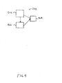
- FIG. 9 is a block diagram of an example arrangement of controller module 254, used to implement portions of method 800.
- Module 254 includes a compare module 904 for performing compare step 805 of method 800. Compare module 904 may include portions of compare module 750 discussed in connection with FIG. 7.
- Module 254 further includes a determining module 906 for performing steps 806 and 807.
- Module 254 also includes a select module 908 for performing step 812.
- Method 500 uses two main sets of filter coefficient thresholds stored in memory 250 to compare against the absolute values of the filter coefficients C.
- the first set of thresholds 260 indicative of channel faults i.e., open/short thresholds 260
- the second set of thresholds 262 indicative of channel length i.e., length thresholds 262
- a set of thresholds including thresholds of different values is used in the present invention.
- a staircase approach is used in the present invention for the open/short thresholds 260 and length thresholds 262.
- Filter coefficients C are divided into three or four groups, and each group has its own corresponding fixed threshold for open short thresholds 260 and length thresholds 262, each being somewhat smaller than the threshold for the previous group.
- the different threshold values follow a staircase of values.
- Initial estimates for values of the open/short thresholds 260 and the length thresholds 262 for an Ethernet system have been determined using an exhaustive system and lab analysis of digital adaptive filtering of many actual twisted pair wires. This analysis has helped to determine that four (4) threshold groups in the open/short thresholds 260 are sufficient for the detection of channel faults. Three threshold groups in the length thresholds 262 are sufficient for the calculation of channel length. Furthermore, the analysis has given reasonable initial estimates for the sizes of each of the threshold groups, and the associated values corresponding to each threshold group. The initial estimates are shown in the following tables:
- the variable C (not to be confused with filter coefficients C) is called the Channel Length Polynomial Linear term, and D is called the Channel Length Polynomial Constant term, and C and D are contained in the second set of constants 258 indicative of channel length.
- the resulting channel fault distance is 0.87109 * 72 - 6.0, or approximately 57 meters.
- the resulting channel length is 0.83594 * 45-6.75, or approximately 31 meters.
Applications Claiming Priority (6)
| Application Number | Priority Date | Filing Date | Title |
|---|---|---|---|
| US39612702P | 2002-07-17 | 2002-07-17 | |
| US396127P | 2002-07-17 | ||
| US281992 | 2002-10-29 | ||
| US282206 | 2002-10-29 | ||
| US10/281,992 US7190718B2 (en) | 2002-07-17 | 2002-10-29 | Method and apparatus for determining a receiver sampling phase for use in diagnosing a channel |
| US10/282,206 US7480326B2 (en) | 2002-07-17 | 2002-10-29 | Channel diagnostic systems and methods |
Publications (2)
| Publication Number | Publication Date |
|---|---|
| EP1420521A2 true EP1420521A2 (de) | 2004-05-19 |
| EP1420521A3 EP1420521A3 (de) | 2005-11-09 |
Family
ID=30448111
Family Applications (1)
| Application Number | Title | Priority Date | Filing Date |
|---|---|---|---|
| EP03016209A Withdrawn EP1420521A3 (de) | 2002-07-17 | 2003-07-17 | System und Verfahren zur Kanaldiagnose |
Country Status (2)
| Country | Link |
|---|---|
| US (2) | US7480326B2 (de) |
| EP (1) | EP1420521A3 (de) |
Cited By (3)
| Publication number | Priority date | Publication date | Assignee | Title |
|---|---|---|---|---|
| WO2007111560A3 (en) * | 2006-03-28 | 2007-12-13 | Ericsson Telefon Ab L M | Filter adaptive frequency resolution |
| US8331430B2 (en) * | 2006-08-02 | 2012-12-11 | Broadcom Corporation | Channel diagnostic systems and methods |
| KR101380448B1 (ko) * | 2005-04-21 | 2014-04-11 | 메르크 세로노 에스. 에이. | 2,3치환된 피라진 술폰아미드 |
Families Citing this family (22)
| Publication number | Priority date | Publication date | Assignee | Title |
|---|---|---|---|---|
| US7239680B2 (en) * | 2002-07-17 | 2007-07-03 | Broadcom Corporation | Methods for performing channel diagnostics |
| US7480326B2 (en) * | 2002-07-17 | 2009-01-20 | Broadcom Corporation | Channel diagnostic systems and methods |
| US7254217B2 (en) * | 2002-12-12 | 2007-08-07 | Adc Dsl Systems, Inc. | Fault characterization using information indicative of echo |
| US7480367B2 (en) * | 2002-12-12 | 2009-01-20 | Adc Dsl Systems, Inc. | Fault characterization using information indicative of echo |
| US7082157B2 (en) * | 2002-12-24 | 2006-07-25 | Realtek Semiconductor Corp. | Residual echo reduction for a full duplex transceiver |
| US7231415B1 (en) * | 2003-04-08 | 2007-06-12 | At&T Corp. | Method and system for provisioning facility-based displays in support of repairing outside network facilities |
| US7460498B2 (en) | 2003-12-04 | 2008-12-02 | Adtran, Inc. | System and method for detecting anomalies along telecommunication lines |
| US7245129B2 (en) * | 2005-02-14 | 2007-07-17 | Texas Instruments Incorporated | Apparatus for and method of cable diagnostics utilizing time domain reflectometry |
| TWI350673B (en) * | 2006-03-07 | 2011-10-11 | Realtek Semiconductor Corp | Method for determining connection status of wired network |
| US20080166122A1 (en) * | 2007-01-08 | 2008-07-10 | Inventec Multimedia & Telecom Corporation | Optical network backup channel switching control device |
| US20080310617A1 (en) * | 2007-06-14 | 2008-12-18 | Infineon Technologies Ag | Transmission Links |
| US8513952B2 (en) | 2007-12-11 | 2013-08-20 | Marvell International Ltd. | Sub-symbol rate cable tester |
| JP5239774B2 (ja) * | 2008-11-18 | 2013-07-17 | 富士通株式会社 | ノード装置 |
| US8452002B2 (en) * | 2009-09-18 | 2013-05-28 | At&T Intellectual Property I, L.P. | Methods, apparatus and articles of manufacture to cancel echo for communication paths having long bulk delays |
| US9077572B1 (en) * | 2012-01-17 | 2015-07-07 | Clariphy Communications, Inc. | Reset in a receiver using center of gravity of equalizer coefficients |
| US8867598B1 (en) | 2012-08-14 | 2014-10-21 | Pmc-Sierra Us, Inc. | Timing and data recovery in feed-forward equalization |
| CN107275726B (zh) * | 2017-06-08 | 2019-06-04 | 西北工业大学 | 一种5节螺旋形滤波器组的汇接方法 |
| WO2020091918A1 (en) * | 2018-10-31 | 2020-05-07 | Commscope Technologies Llc | Systems and methods for automated network cabling integrity monitoring |
| TWI730422B (zh) * | 2019-09-23 | 2021-06-11 | 瑞昱半導體股份有限公司 | 接收器及相關的訊號處理方法 |
| CN112583431B (zh) * | 2019-09-29 | 2022-05-17 | 瑞昱半导体股份有限公司 | 接收器及相关的信号处理方法 |
| US11496254B2 (en) * | 2020-08-28 | 2022-11-08 | Rockwell Automation Technologies, Inc. | System and method for testing filters in redundant signal paths |
| TWI819276B (zh) * | 2021-02-20 | 2023-10-21 | 瑞昱半導體股份有限公司 | 通道估測方法 |
Citations (2)
| Publication number | Priority date | Publication date | Assignee | Title |
|---|---|---|---|---|
| US4547633A (en) | 1982-12-09 | 1985-10-15 | International Standard Electric Corporation | Method of and circuit for locating faults in a digital telecommunication subscriber termination |
| EP0268391A1 (de) | 1986-10-22 | 1988-05-25 | BRITISH TELECOMMUNICATIONS public limited company | Aufspüren von Fehlern in Übertragungsleitungen |
Family Cites Families (54)
| Publication number | Priority date | Publication date | Assignee | Title |
|---|---|---|---|---|
| US3962637A (en) | 1974-11-11 | 1976-06-08 | Hycom Incorporated | Ultrafast adaptive digital modem |
| GB2111354B (en) | 1981-11-19 | 1985-06-19 | Standard Telephones Cables Ltd | Echo canceller |
| JPS6165551A (ja) | 1984-09-06 | 1986-04-04 | Nec Corp | タイミング位相制御装置 |
| US4789994A (en) | 1987-08-12 | 1988-12-06 | American Telephone And Telegraph Company, At&T Bell Laboratories | Adaptive equalizer using precursor error signal for convergence control |
| US5099436A (en) | 1988-11-03 | 1992-03-24 | Allied-Signal Inc. | Methods and apparatus for performing system fault diagnosis |
| US5351247A (en) | 1988-12-30 | 1994-09-27 | Digital Equipment Corporation | Adaptive fault identification system |
| CA2047557C (en) | 1990-07-20 | 1996-12-10 | Mitsuo Kakuishi | Received data adjusting device |
| US5166954A (en) | 1991-03-05 | 1992-11-24 | At&T Bell Laboratories | Adaptive system for measuring the broadband signal-to-noise ratio of a transmission channel |
| US5155742A (en) | 1991-05-03 | 1992-10-13 | Bell Communications Research, Inc. | Time dispersion equalizer receiver with a time-reversal structure for TDMA portable radio systems |
| EP0515761A1 (de) | 1991-05-31 | 1992-12-02 | International Business Machines Corporation | Verfahren und Einrichtung zur adaptiven Entzerrung eines Signals in einer Datenendeinrichtung |
| DE4220410C1 (de) | 1992-06-19 | 1993-11-25 | Siemens Ag | Verfahren zum Bestimmen eines Fehlers auf einer elektrischen Übertragungsleitung |
| GB9222103D0 (en) * | 1992-10-21 | 1992-12-02 | Lotus Car | Adaptive control system |
| EP0612186B1 (de) | 1993-02-13 | 1999-06-09 | Lg Electronics Inc. | Vorrichtung zur Aufnahme/Wiedergabe von Videosignalen mit hoher Auflösung |
| US5528516A (en) | 1994-05-25 | 1996-06-18 | System Management Arts, Inc. | Apparatus and method for event correlation and problem reporting |
| US6233274B1 (en) | 1995-04-27 | 2001-05-15 | Wavetek Wandel Goltermann | Non-invasive digital cable test system |
| US5751766A (en) | 1995-04-27 | 1998-05-12 | Applied Signal Technology, Inc. | Non-invasive digital communications test system |
| US5872815A (en) | 1996-02-16 | 1999-02-16 | Sarnoff Corporation | Apparatus for generating timing signals for a digital television signal receiver |
| GB9620288D0 (en) | 1996-09-28 | 1996-11-13 | Univ Strathclyde | Automatic fault location in cabling systems |
| JP3335862B2 (ja) * | 1997-01-28 | 2002-10-21 | シャープ株式会社 | 波形等化器及びこれを備えたディジタル記録再生装置 |
| KR100224837B1 (ko) | 1997-02-21 | 1999-10-15 | 윤종용 | 디지털 vcr의 적응적인 신호 처리방법 및 그 회로 |
| US6144697A (en) * | 1998-02-02 | 2000-11-07 | Purdue Research Foundation | Equalization techniques to reduce intersymbol interference |
| US6650768B1 (en) | 1998-02-19 | 2003-11-18 | International Business Machines Corporation | Using time resolved light emission from VLSI circuit devices for navigation on complex systems |
| US6226356B1 (en) | 1998-06-12 | 2001-05-01 | Legerity Inc. | Method and apparatus for power regulation of digital data transmission |
| US6289047B1 (en) * | 1998-08-28 | 2001-09-11 | Broadcom Corporation | Dynamic regulation of power consumption of a high-speed communication system |
| US6414990B1 (en) | 1998-09-29 | 2002-07-02 | Conexant Systems, Inc. | Timing recovery for a high speed digital data communication system based on adaptive equalizer impulse response characteristics |
| US6434233B1 (en) * | 1998-09-30 | 2002-08-13 | Conexant Systems, Inc. | Method and apparatus for canceling periodic interference signals in a digital data communication system |
| US6650699B1 (en) | 1999-01-21 | 2003-11-18 | International Business Machines Corporation | Methods and apparatus for timing recovery from a sampled and equalized data signal |
| US6590930B1 (en) * | 1999-07-22 | 2003-07-08 | Mysticom Ltd. | Local area network diagnosis |
| US6833875B1 (en) * | 1999-09-02 | 2004-12-21 | Techwell, Inc. | Multi-standard video decoder |
| US6898185B1 (en) | 1999-10-20 | 2005-05-24 | Broadcom Corporation | Diagnostics of cable and link performance for a high-speed communication system |
| US6744854B2 (en) | 1999-12-09 | 2004-06-01 | Harris Corporation | Detection of bridge taps by frequency domain reflectometry-based signal processing with precursor signal conditioning |
| US6856655B1 (en) | 1999-12-21 | 2005-02-15 | Texas Instruments Incorporated | Timing recovery device and method for telecommunications systems |
| EP2267914A3 (de) | 2000-01-07 | 2012-09-26 | Aware, Inc. | Verfahren und Vorrichtung zur Bestimmung der Leitungslänge und der Brückenabgrifflänge in einer Übertragungsleitung |
| US6985521B1 (en) * | 2000-01-07 | 2006-01-10 | Ikanos Communication, Inc | Method and apparatus for channel estimation for X-DSL communications |
| US6534996B1 (en) | 2000-03-27 | 2003-03-18 | Globespanvirata, Inc. | System and method for phone line characterization by time domain reflectometry |
| JP3786343B2 (ja) * | 2000-05-12 | 2006-06-14 | 日本ビクター株式会社 | 光ディスク再生装置 |
| DE10025566C2 (de) | 2000-05-24 | 2003-04-30 | Infineon Technologies Ag | Verfahren und Vorrichtung zur Taktregelung eines digitalen Empfängers |
| US6529549B1 (en) | 2000-07-27 | 2003-03-04 | 2Wire, Inc. | System and method for an equalizer-based symbol timing loop |
| US6448781B1 (en) | 2000-10-06 | 2002-09-10 | Northrop Grumman Corporation | Method and system for analyzing cable faults |
| US6934655B2 (en) | 2001-03-16 | 2005-08-23 | Mindspeed Technologies, Inc. | Method and apparatus for transmission line analysis |
| US6885954B2 (en) | 2001-03-16 | 2005-04-26 | Mindspeed Technologies, Inc. | Sequence time domain reflectometry using complementary golay codes |
| US6947857B2 (en) | 2001-03-16 | 2005-09-20 | Mindspeed Technologies, Inc. | Optical sequence time domain reflectometry during data transmission |
| US20020168001A1 (en) | 2001-05-09 | 2002-11-14 | Jeffrey Ramsey | Systems and method for determining the phase angle response in a CATV system |
| US20030018981A1 (en) | 2001-07-17 | 2003-01-23 | Jeffrey Ramsey | System and method for displaying CATV diagnostic data |
| US6901243B2 (en) * | 2001-11-08 | 2005-05-31 | Qualcomm, Incorporated | Method and apparatus for mitigating adjacent channel interference in a wireless communication system |
| US7305050B2 (en) | 2002-05-13 | 2007-12-04 | Marvell Dspc Ltd. | Method and apparatus for processing signals received from a channel having a variable channel length |
| US6674518B1 (en) | 2002-07-01 | 2004-01-06 | At&T Corp. | Method and apparatus for optical time domain reflectometry (OTDR) analysis |
| US7239680B2 (en) | 2002-07-17 | 2007-07-03 | Broadcom Corporation | Methods for performing channel diagnostics |
| US7480326B2 (en) | 2002-07-17 | 2009-01-20 | Broadcom Corporation | Channel diagnostic systems and methods |
| US7373282B2 (en) | 2002-07-31 | 2008-05-13 | Tektronix, Inc. | Fault severity check and source identification |
| US7636388B2 (en) | 2004-07-01 | 2009-12-22 | Broadcom Corporation | Channel fault detection for channel diagnostic systems |
| US7627026B2 (en) | 2004-07-01 | 2009-12-01 | Broadcom Corporation | Threshold setting using piecewise linear approximation for channel diagnostic systems |
| US7627025B2 (en) * | 2004-07-01 | 2009-12-01 | Broadcom Corporation | Echo canceller gain control for channel diagnostic systems |
| WO2006032124A1 (en) | 2004-09-24 | 2006-03-30 | Bce Inc. | System and method for fault identification |
-
2002
- 2002-10-29 US US10/282,206 patent/US7480326B2/en not_active Expired - Fee Related
- 2002-10-29 US US10/281,992 patent/US7190718B2/en not_active Expired - Fee Related
-
2003
- 2003-07-17 EP EP03016209A patent/EP1420521A3/de not_active Withdrawn
Patent Citations (2)
| Publication number | Priority date | Publication date | Assignee | Title |
|---|---|---|---|---|
| US4547633A (en) | 1982-12-09 | 1985-10-15 | International Standard Electric Corporation | Method of and circuit for locating faults in a digital telecommunication subscriber termination |
| EP0268391A1 (de) | 1986-10-22 | 1988-05-25 | BRITISH TELECOMMUNICATIONS public limited company | Aufspüren von Fehlern in Übertragungsleitungen |
Cited By (3)
| Publication number | Priority date | Publication date | Assignee | Title |
|---|---|---|---|---|
| KR101380448B1 (ko) * | 2005-04-21 | 2014-04-11 | 메르크 세로노 에스. 에이. | 2,3치환된 피라진 술폰아미드 |
| WO2007111560A3 (en) * | 2006-03-28 | 2007-12-13 | Ericsson Telefon Ab L M | Filter adaptive frequency resolution |
| US8331430B2 (en) * | 2006-08-02 | 2012-12-11 | Broadcom Corporation | Channel diagnostic systems and methods |
Also Published As
| Publication number | Publication date |
|---|---|
| US20040013178A1 (en) | 2004-01-22 |
| US7480326B2 (en) | 2009-01-20 |
| US20040013208A1 (en) | 2004-01-22 |
| EP1420521A3 (de) | 2005-11-09 |
| US7190718B2 (en) | 2007-03-13 |
Similar Documents
| Publication | Publication Date | Title |
|---|---|---|
| US7190718B2 (en) | Method and apparatus for determining a receiver sampling phase for use in diagnosing a channel | |
| US7239680B2 (en) | Methods for performing channel diagnostics | |
| US7636388B2 (en) | Channel fault detection for channel diagnostic systems | |
| US7627025B2 (en) | Echo canceller gain control for channel diagnostic systems | |
| US7627026B2 (en) | Threshold setting using piecewise linear approximation for channel diagnostic systems | |
| US7245129B2 (en) | Apparatus for and method of cable diagnostics utilizing time domain reflectometry | |
| EP1222767B1 (de) | Diagnose von kabel und verbindungsleistung für ein kommunikationssystem mit hoher datenübertragungsgeschwindigkeit | |
| JP4694093B2 (ja) | 多数搬送波dsl環境でブロードバンド信号を使用して伝送回線を特性付けるためのシステムおよび方法 | |
| US8331508B2 (en) | Narrowband interference cancellation method and circuit | |
| EP1246398B1 (de) | Verfahren und Vorrichtung zur Durchführung eines diagnostischen Tests unter Zuhilfenahme eines Transceivers | |
| US5521908A (en) | Method and apparatus for providing reduced complexity echo cancellation in a multicarrier communication system | |
| JP2679000B2 (ja) | 適応等化システムおよび方法 | |
| US5577116A (en) | Apparatus and method for echo characterization of a communication channel | |
| US20060182014A1 (en) | Apparatus for and method of characterization of ethernet cable impairments | |
| US8331430B2 (en) | Channel diagnostic systems and methods | |
| US20020191779A1 (en) | System for convolutional echo cancellation by iterative autocorrelation | |
| US20050063323A1 (en) | Method and circuit arrangement for determination of transmission parameters | |
| US20210014087A1 (en) | Receiver with selectable digital equalization filter options | |
| US20050123031A1 (en) | System and method for detecting anomalies along telecommunication lines | |
| US20020181699A1 (en) | System for convolutional echo cancellation by iterative autocorrelation | |
| JP7417492B2 (ja) | 通信装置、通信システム、通信方法 | |
| JP4410098B2 (ja) | 等化用遅延時間推定 | |
| US7239665B2 (en) | Selection of pre-computed equalizer based on channel characteristic | |
| EP1376997A1 (de) | Verfahren zum Testen und Anpassen der Audioeinheitsparameter für ein Telekommunikationssystem | |
| CN114731317A (zh) | 用于确定通信信道的逆脉冲响应的方法 |
Legal Events
| Date | Code | Title | Description |
|---|---|---|---|
| PUAI | Public reference made under article 153(3) epc to a published international application that has entered the european phase |
Free format text: ORIGINAL CODE: 0009012 |
|
| AK | Designated contracting states |
Kind code of ref document: A2 Designated state(s): AT BE BG CH CY CZ DE DK EE ES FI FR GB GR HU IE IT LI LU MC NL PT RO SE SI SK TR |
|
| AX | Request for extension of the european patent |
Extension state: AL LT LV MK |
|
| PUAL | Search report despatched |
Free format text: ORIGINAL CODE: 0009013 |
|
| AK | Designated contracting states |
Kind code of ref document: A3 Designated state(s): AT BE BG CH CY CZ DE DK EE ES FI FR GB GR HU IE IT LI LU MC NL PT RO SE SI SK TR |
|
| AX | Request for extension of the european patent |
Extension state: AL LT LV MK |
|
| 17P | Request for examination filed |
Effective date: 20060509 |
|
| AKX | Designation fees paid |
Designated state(s): DE FR GB |
|
| RAP1 | Party data changed (applicant data changed or rights of an application transferred) |
Owner name: BROADCOM CORPORATION |
|
| 17Q | First examination report despatched |
Effective date: 20110216 |
|
| STAA | Information on the status of an ep patent application or granted ep patent |
Free format text: STATUS: THE APPLICATION IS DEEMED TO BE WITHDRAWN |
|
| 18D | Application deemed to be withdrawn |
Effective date: 20130201 |