EP1420504B1 - Interrupteur de fin de course pour actionneur linéaire - Google Patents
Interrupteur de fin de course pour actionneur linéaire Download PDFInfo
- Publication number
- EP1420504B1 EP1420504B1 EP03405802A EP03405802A EP1420504B1 EP 1420504 B1 EP1420504 B1 EP 1420504B1 EP 03405802 A EP03405802 A EP 03405802A EP 03405802 A EP03405802 A EP 03405802A EP 1420504 B1 EP1420504 B1 EP 1420504B1
- Authority
- EP
- European Patent Office
- Prior art keywords
- limit switch
- switch unit
- slider
- switching
- drive
- Prior art date
- Legal status (The legal status is an assumption and is not a legal conclusion. Google has not performed a legal analysis and makes no representation as to the accuracy of the status listed.)
- Expired - Lifetime
Links
- 230000033001 locomotion Effects 0.000 claims description 30
- 230000005540 biological transmission Effects 0.000 claims description 14
- 230000004044 response Effects 0.000 claims description 7
- 238000006073 displacement reaction Methods 0.000 claims description 4
- 230000001419 dependent effect Effects 0.000 claims 1
- 230000000694 effects Effects 0.000 description 10
- 230000007935 neutral effect Effects 0.000 description 5
- 230000009471 action Effects 0.000 description 2
- 230000006378 damage Effects 0.000 description 2
- 238000001514 detection method Methods 0.000 description 2
- 230000007246 mechanism Effects 0.000 description 2
- 230000009467 reduction Effects 0.000 description 2
- 102000004315 Forkhead Transcription Factors Human genes 0.000 description 1
- 108090000852 Forkhead Transcription Factors Proteins 0.000 description 1
- 208000027418 Wounds and injury Diseases 0.000 description 1
- 210000003746 feather Anatomy 0.000 description 1
- 208000014674 injury Diseases 0.000 description 1
- 238000009434 installation Methods 0.000 description 1
- 238000004519 manufacturing process Methods 0.000 description 1
- 238000013021 overheating Methods 0.000 description 1
- 239000011295 pitch Substances 0.000 description 1
- 230000003068 static effect Effects 0.000 description 1
Images


Classifications
-
- H—ELECTRICITY
- H02—GENERATION; CONVERSION OR DISTRIBUTION OF ELECTRIC POWER
- H02K—DYNAMO-ELECTRIC MACHINES
- H02K7/00—Arrangements for handling mechanical energy structurally associated with dynamo-electric machines, e.g. structural association with mechanical driving motors or auxiliary dynamo-electric machines
- H02K7/06—Means for converting reciprocating motion into rotary motion or vice versa
-
- F—MECHANICAL ENGINEERING; LIGHTING; HEATING; WEAPONS; BLASTING
- F16—ENGINEERING ELEMENTS AND UNITS; GENERAL MEASURES FOR PRODUCING AND MAINTAINING EFFECTIVE FUNCTIONING OF MACHINES OR INSTALLATIONS; THERMAL INSULATION IN GENERAL
- F16H—GEARING
- F16H25/00—Gearings comprising primarily only cams, cam-followers and screw-and-nut mechanisms
- F16H25/18—Gearings comprising primarily only cams, cam-followers and screw-and-nut mechanisms for conveying or interconverting oscillating or reciprocating motions
- F16H25/20—Screw mechanisms
- F16H25/2015—Means specially adapted for stopping actuators in the end position; Position sensing means
-
- F—MECHANICAL ENGINEERING; LIGHTING; HEATING; WEAPONS; BLASTING
- F16—ENGINEERING ELEMENTS AND UNITS; GENERAL MEASURES FOR PRODUCING AND MAINTAINING EFFECTIVE FUNCTIONING OF MACHINES OR INSTALLATIONS; THERMAL INSULATION IN GENERAL
- F16H—GEARING
- F16H25/00—Gearings comprising primarily only cams, cam-followers and screw-and-nut mechanisms
- F16H25/18—Gearings comprising primarily only cams, cam-followers and screw-and-nut mechanisms for conveying or interconverting oscillating or reciprocating motions
- F16H25/20—Screw mechanisms
- F16H25/24—Elements essential to such mechanisms, e.g. screws, nuts
- F16H25/2454—Brakes; Rotational locks
-
- H—ELECTRICITY
- H02—GENERATION; CONVERSION OR DISTRIBUTION OF ELECTRIC POWER
- H02K—DYNAMO-ELECTRIC MACHINES
- H02K11/00—Structural association of dynamo-electric machines with electric components or with devices for shielding, monitoring or protection
- H02K11/20—Structural association of dynamo-electric machines with electric components or with devices for shielding, monitoring or protection for measuring, monitoring, testing, protecting or switching
- H02K11/21—Devices for sensing speed or position, or actuated thereby
-
- F—MECHANICAL ENGINEERING; LIGHTING; HEATING; WEAPONS; BLASTING
- F16—ENGINEERING ELEMENTS AND UNITS; GENERAL MEASURES FOR PRODUCING AND MAINTAINING EFFECTIVE FUNCTIONING OF MACHINES OR INSTALLATIONS; THERMAL INSULATION IN GENERAL
- F16H—GEARING
- F16H25/00—Gearings comprising primarily only cams, cam-followers and screw-and-nut mechanisms
- F16H25/18—Gearings comprising primarily only cams, cam-followers and screw-and-nut mechanisms for conveying or interconverting oscillating or reciprocating motions
- F16H25/20—Screw mechanisms
- F16H25/24—Elements essential to such mechanisms, e.g. screws, nuts
- F16H25/2454—Brakes; Rotational locks
- F16H2025/2463—Brakes; Rotational locks using a wrap spring brake, i.e. a helical wind up spring for braking or locking
Definitions
- the invention relates to an end switch unit for a linear drive according to the features of patent claim 1.
- Linear drives with a linearly movable thrust tube and a guided in the thrust tube and driven by a drive unit spindle are now widely used. They are often used to linearly move devices or device parts short distances or to open and close flaps, lids and the like.
- US-A-3682283 discloses a motor-driven actuator comprising an electric motor for driving a spindle and a torque tube engaged therewith, the rotation of the spindle resulting in reciprocal movement of the torque tube.
- a safety mechanism is integrated in the actuator to automatically stop the engine when overloaded.
- the safety mechanism consists of a pair of limit switches which are actuated by displacement of the spindle.
- US-A-5094114 discloses an apparatus for controlling the feed rate of a machine table.
- the rotation of a ball screw is converted into a reciprocal movement of the table.
- a position detector signals the position of the ball screw and a speed reduction device can then reduce the revolutions of the ball screw.
- GB 643,863 A discloses a linear actuator, which is used as an actuator for Anstellklappen an aircraft application.
- This linear drive includes a linearly movable in a jacket tube torque tube, which by a driven Spindle for retraction and extension is performed.
- linear drives including products of the Applicant
- a jacket tube also called guide tube
- the torque tube linearly displaceable shift rod whose effective reciprocating motion by suitably mounted driver parts on the torque tube only a small fraction of the total
- the reciprocating motion of the torque tube is transmitted to limit switches which are fixedly mounted in the vicinity of the drive device.
- spring brakes are an extremely effective and simple means for preventing rotational force transmission in a direction of rotation in which no torque transmission is permitted, they also have the disadvantage that, by design, a small rotational path (angle of rotation) until effective entry of the full braking effect necessary is. This has the consequence that a load lifted by the linear drive when turning off the drive motor in the drive unit is able to turn the spindle again by a small angle of rotation in the opposite direction. This, in turn, causes a small limit to that limit switch used to detect the spindle position in the fully extended position but consequential 'slumping' of spindle and torque tube (ie, it results in a small retraction of the spindle in the torque tube).
- the aim of the invention is to provide a limit switch unit for a linear drive, in which the mentioned problems can be avoided, but nevertheless the advantages of a equipped with a wrap spring brake (or equipped with a same or similar acting device) and switching-bar-operated design can be exploited ,
- a linearly movable between the torque tube and a jacket tube shift rod and between a drive shaft of the drive unit and the spindle built-in Braking device for transmission or deceleration of rotational movements (eg a wrap spring brake, a friction clutch or the like), in which at least one limit switch of the limit switch unit is actuated by the shift rod, which has at least one Limit switch the limit switch unit with respect to a displacement movement of the shift rod, at least in an extended position of the torque tube on a hysteresis.
- the hysteresis is tuned to a conditional on the mainspring brake response path when switching off the drive motor.
- a load is pressed against a load by the linear drive according to the invention (for example the lifting of a window roof)
- at least the limit switch for detecting the maximally extended position of the torque tube must be provided with a switching hysteresis, because here the mentioned disturbing self-interrupting effect can occur.
- the maximum retracted position there is basically no need for a switching hysteresis in this situation, because here the forces always act in a direction in which no self-interrupting effect can occur.
- the detection of the maximum retracted position of the torque tube is equipped with a switching hysteresis, because it is also possible in principle to load the linear drive to train and then occurs the disturbing self-interrupting effect in the detection of the maximum retracted position of the torque tube. With little extra effort, the range of application of the linear drive can be considerably increased.
- a second limit switch is used to detect the maximum extended position of the torque tube, a first limit switch and to detect the maximum retracted position of the torque tube. It can then be two equal, cost effective and easy built limit switches are used. In principle, solutions are also possible in which only one limit switch, for example one with a changeover contact, is used to detect the two end positions of the torque tube. Likewise, contactless limit switches can be used.
- the constructive solution according to the invention preferably uses a shifting part which can be displaced with respect to a slide, wherein the slide is connected to the switching rod and therefore participates in its movements.
- the slide and the switching part are both guided linearly on a guide piece.
- the switching member has a recess in which the slider relative to the switching member is reciprocable, the switching member is entrained by the slide and the entrainment movement according to the sliding movement of the shift rod causes the hysteresis.
- the parts are simple and easy to manufacture, and they can be easily integrated on a circuit board with the limit switches in such a way that assembly, installation, function testing and replacement are particularly easy.
- the unit is also easily replaceable as a replacement for units without a hysteresis function.
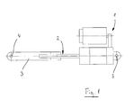
- FIG. 1 shows the basic arrangement of a generic linear actuator. This essentially comprises a drive unit 1 (with a drive motor and a reduction gear) and a driven by the drive unit 1 spindle 2, which is guided in a linearly movable torque tube 3.
- a clevis 4 is used for attachment of a part to be moved (not shown), while the linear drive itself can be fastened by means of a fastening part 5 somewhere.
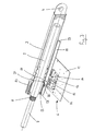
- FIG. 2 shows a 3D partial section through a torque tube 3 with a spindle 2 in the extended position in a linear drive with an inventive end switch unit 6.
- extended position is to be understood as the position in which the spindle 2 is completely turned out of the torque tube 3 (maximum) or moved out.
- retracted position is understood to be the position in which the spindle 2 is completely screwed (or screwed) into the torque tube 3.
- the spindle 2 is driven by a drive shaft 7 of the drive unit 1.
- Drive shaft 7 and spindle 2, however, are not rigidly connected to each other, interposed is a so-called (not shown) wrap spring brake (or more generally: brake device for transmission or deceleration of rotational movements), which is mounted on a toothing 8 of the drive shaft 7.
- the wrap spring brake serves the purpose, on the one hand to enable a transmission of rotational power from the drive shaft 7 to the spindle 2, but on the other hand to brake or prevent a rotational force transmission from the spindle 2 to the drive axle 7.
- the actual transmission of the rotational movement of the spindle 2 to the linear movement of the torque tube 3 is effected by a spindle nut 9 which is fixedly connected to the torque tube 3.
- a spindle thread of the spindle 2 and an internal thread of the spindle nut 9 is not shown.
- a push tube guide 10 is attached at the lower end of the push tube 3. With the push tube guide 10, the torque tube 3 is guided in a fixedly connected to the drive unit 1 casing tube 11. For the sake of clarity, the drive unit 1 with the exception of the drive shaft 7 is not shown here.
- a printed circuit board 12 on which the inventive end switch unit 6 is arranged.
- the latter contains, among other things a first limit switch 13 for detecting the extended position of the push tube 3 and the spindle 2 and a second limit switch 14 for detecting the retracted position of the push tube 3 and the spindle 2.
- a slider 15 and a switching member 16 are also visible.
- the slider 15th is connected via a fixing pin 17 fixed to a shift rod 18.
- the switching member 16 has a guide pin 19 which slides in an elongated guide slot 20 of the shift rod 18. Because of the fixed connection between the shift rod 18 and the slider 15, the latter makes any movement of the shift rod 18 with.
- the switching part 16, however, is displaceable relative to the slider 15. Further explanations on the components and on the function of the limit switch unit cf. the description of FIGS. 5 to 9 ,
- FIG. 2 Furthermore, from the FIG. 2 is a leading edge 21 and a trailing edge 22 of the push tube guide 10.
- the shift rod 18, which in turn is guided between the torque tube 3 and the casing tube 11 is provided at both the front and at the rear end, each with a bend 23.
- the front edge 21 of the push tube guide 10 detects the angling 23 of the shift rod 18 and pulls the latter in the in FIG. 2 shown position. This causes the slide 15 and thus also the switching member 16 are pulled along, whereby the switching part passes into the region of the first limit switch 13, which upon actuation of the first limit switch 13, the extension of the torque tube 3 by turning off the drive unit 1 (electrical switching off the drive motor ) is stopped in the extended position.
- FIG. 3 a 3D partial section through a torque tube 3 with a spindle 2 in the retracted position in a linear drive according to Fig. 2 ,
- the push tube 3 detects the trailing edge 22 of the push tube guide 10, the other bend 23 of the shift rod 18 and pulls the latter in the in FIG. 3 shown position.
- This causes the slider 15 and thus the switching member 16 are pulled along, whereby the switching member 16 enters the region of the second limit switch 14, which upon actuation of the second limit switch 14, the retraction of the torque tube 3 by switching off the drive unit 1 (electrical switching off of Drive motor) is stopped in the retracted position.
- the jacket tube 11 in the FIG. 3 not shown.
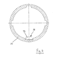
- FIG. 4 shows a cross section through a jacket tube 11.
- the shift rod 18 in the jacket tube 11 and between the jacket tube 11 and not shown here Schubrohr 3 is guided. It can also be seen one of the bends 23 of the shift rod 18th
- wrap spring brakes are an extremely effective and simple means for preventing torque transmission in a direction of rotation in which no torque transmission is allowed, but they also have the disadvantage that, by design, a small rotational path exists until the full braking effect occurs effectively.
- FIG. 1 - 4 described linear drive operated in such a way that a load is lifted via the fork head 4 during extension, this will have the consequence that the load when switching off the drive unit (ie, when the electric drive of the drive motor after the response of the first limit switch 13), the spindle again at a small angle of rotation in the opposite direction Able to turn direction.
- a switching hysteresis is introduced for the limit switch 13, at least for the extended position of the push tube 3.
- the switching hysteresis is introduced equally for both limit switches 13, 14, so that the advantages of the invention can also be utilized with tensile loads. This switching hysteresis is generated in the limit switch unit 6.
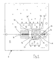
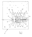
- FIG. 5 shows a plan view of an inventive end switch unit 6 in the retracted position of the spindle 2. All components of the limit switch unit 6 are arranged on the printed circuit board 12.
- the switching part 16 is arranged displaceably relative to the slider 15, both of which are arranged in each case movably on a guide piece 25 and guided linearly. In this case, the slide 15 is supported on both sides with springs 26 relative to the guide piece 25. When the printed circuit board 12 has been removed, this would mean that the slider 15 of the springs 26 in a neutral middle position (see also Fig. 8 and 9 ) is pressed.
- the switching part 16 has a recess 27, in which the slide 15 is reciprocable relative to the switching part 16.
- the switching member 16 is taken from the slider 15.
- the direction of movement of the switching member 16 takes place only when the slider 15 has already covered a path (in the reverse direction) in the recess 27 again. This results in a hysteresis function in the movement.
- the switching part 16 in turn has obliquely applied switching edges 28 ', 28 ", which actuate either a contact pin 29 of the first limit switch 13 or a contact pin 30 of the second limit switch 14 in the maximum deflected positions of the slide 15.
- an emergency limit switch 31 is not relevant in connection with the hysteresis function and is always contacted in normal operation.
- the emergency limit switch 31 is provided in the event that one of the limit switches 13,14 does not work and the deflecting movements of the slider 15 and the switching member 16 are not stopped in time. The switching member 16 then leaves the area in which the contact pin of the emergency limit switch 31 is pressed permanently and as a result, the power supply to the drive motor is completely interrupted.
- FIG. 6 is the spindle 2 relative to the torque tube 3 in the maximum extended position (see also Fig. 2 ), in a position that the torque tube 3 and spindle 2 immediately before the response of the wrap spring brake and thereby caused low return or 'collapse' occupy.
- the slide 15 is in that maximum deflected slide position in which the switching edge 28 'of the switching member 16 contacts the contact pin 29 of the first limit switch 13, whereby the extension movement of the linear drive is stopped in this position.
- the spindle 2 is still opposite the thrust tube 3 in the maximum extended position (see also Fig. 2 ), in a position that the torque tube 3 and spindle 2 immediately after the response of the wrap spring brake and the resulting low return or 'collapse' occupy. Because of the low return of the spindle 2, the shift rod 18 and thus also the slider 15 is shifted slightly in the opposite direction. The switching member 16, however, remains in the position that it is just before the response of the wrap spring brake had reached (cf Fig. 6 ). The first limit switch 13 is still in the contacted state.
- the dimensioning of the recess 27 and the slider 15 must be such that the return or Bremswegeinl the wrap spring brake is not greater than the range of motion, the slider 15 has in the recess 27.
- the desired switching hysteresis is achieved, which prevents the disturbing self-interrupting effect can occur.
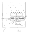
- FIGS. 8 and 9 show finally still top views of the limit switch unit in a first and a second neutral position.
- the spindle 2 is located opposite the torque tube 3 neither in the maximum extended nor in the maximum retracted position. This means that neither the front edge 21 nor the trailing edge 22 of the push tube guide 10 touches one or the other bend 23 of the shift rod 18 and thus the position of the shift rod 18 in these intermediate layers does not depend on the mutual position of the thrust tube 3 and spindle 2. Rather, here the slider 15 (with the shift rod 18) is pressed according to the action of the springs 26 in a middle position and the switching part 16 takes in the sequence, the first or second neutral position, depending on which end position the limit switch unit 6 reached the center position ,
Claims (10)
- Unité d'interrupteur de fin de course (6) pour un entraînement linéaire comprenant- une unité d'entraînement (1) avec un moteur d'entraînement,- une broche (2) guidée dans un tube télescopique (3) pouvant être déplacé linéairement et entraînée par l'unité d'entraînement (1) et- une tige de commutation (18) pouvant être déplacée également linéairement entre le tube télescopique (3) et un tube d'enveloppe (11) et- un dispositif de freinage monté entre un axe d'entraînement (7) de l'unité d'entraînement (1) et la broche (2) pour la transmission ou le ralentissement de mouvements de rotation,
au moins un fin de course de l'unité de fin de course (6) pouvant être actionné par la tige de commutation (18),
caractérisée en ce que
le au moins un fin de course de l'unité de fin de course présente une hystérésis de commutation par rapport à un mouvement de déplacement de la tige de commutation (18) au moins dans une position déployée du tube télescopique (3), l'hystérésis de commutation étant adaptée à une course de réaction conditionnée essentiellement par le dispositif de freinage pour la transmission ou le ralentissement de mouvements de rotation lors de la déconnexion du moteur d'entraînement. - Unité de fin de course selon la revendication 1, caractérisée en ce que le dispositif de freinage pour la transmission ou le ralentissement de mouvements de rotation est un frein à ressort enroulé.
- Unité de fin de course selon la revendication 1 ou 2, caractérisée en ce que le au moins un fin de course de l'unité de fin de course (6) présente une hystérésis de commutation par rapport à une position de commutation de la tige de commutation (18) aussi bien dans une position déployée que dans une position rentrée du tube télescopique (3).
- Unité de fin de course selon l'une des revendications 1 à 3, caractérisée en ce que le au moins un fin de course travaille de façon mécanique ou sans contact.
- Unité de fin de course selon l'une des revendications 1 à 4, caractérisée en ce que l'unité de fin de course (6) présente un premier fin de course mécanique (13) pour une position déployée du tube télescopique (3) et un second fin de course (14) mécanique pour une position rentrée du tube télescopique (3).
- Unité de fin de course selon la revendication 5, caractérisée en ce que le premier et le second fins de course (13, 14) peuvent être actionnés par une partie de commutation (16) coulissante par rapport à un coulisseau (15) et le coulisseau (15) est relié à la tige de commutation (18).
- Unité de fin de course selon la revendication 6, caractérisée en ce que le coulisseau (15) et la partie de commutation (16) coulissante par rapport au coulisseau (15) sont guidés linéairement par une pièce de guidage (25) et le coulisseau (15) est soutenu par rapport à la pièce de guidage (25) des deux côtés par des ressorts (26).
- Unité de fin de course selon la revendication 6 ou 7, caractérisée en ce que la partie de commutation (16) présente un évidement (27) dans lequel le coulisseau (15) peut se déplacer d'un côté et de l'autre par rapport à la partie de commutation (16), la partie de commutation (16) pouvant être entraînée par le coulisseau (15) et le mouvement d'entraînement entraînant l'hystérésis de commutation en raison du mouvement de déplacement de la tige de commutation,
- Unité de fin de course selon la revendication 6, caractérisée en ce que le premier et le second fins de course (13, 14) de l'unité de fin de course peuvent être actionnés par l'intermédiaire de la partie de commutation (16) et du coulisseau (15) et d'une goupille de fixation (17) reliant le coulisseau (15) à la tige de commutation (18) et en ce qu'une broche de guidage (19) est placée également sur la partie de commutation (16), goupille par laquelle l'entraînement linéaire peut être déconnecté lors de la défaillante de la goupille de fixation.
- Unité de fin de course selon la revendication 5, caractérisée en ce que l'entraînement linéaire peut être déconnecté par l'intermédiaire d'un fin de course de secours (31) lors de la défaillance du premier et du second fins de course (13, 14).
Applications Claiming Priority (2)
| Application Number | Priority Date | Filing Date | Title |
|---|---|---|---|
| CH19242002 | 2002-11-15 | ||
| CH19242002 | 2002-11-15 |
Publications (2)
| Publication Number | Publication Date |
|---|---|
| EP1420504A1 EP1420504A1 (fr) | 2004-05-19 |
| EP1420504B1 true EP1420504B1 (fr) | 2012-06-13 |
Family
ID=32111468
Family Applications (1)
| Application Number | Title | Priority Date | Filing Date |
|---|---|---|---|
| EP03405802A Expired - Lifetime EP1420504B1 (fr) | 2002-11-15 | 2003-11-10 | Interrupteur de fin de course pour actionneur linéaire |
Country Status (1)
| Country | Link |
|---|---|
| EP (1) | EP1420504B1 (fr) |
Families Citing this family (7)
| Publication number | Priority date | Publication date | Assignee | Title |
|---|---|---|---|---|
| US7992460B2 (en) | 2006-09-09 | 2011-08-09 | Stabilus Gmbh | Drive device |
| US8358096B2 (en) | 2008-06-27 | 2013-01-22 | Linak A/S | Linear actuator |
| EP2655935B1 (fr) | 2010-12-21 | 2015-01-28 | Linak A/S | Actionneur linéaire |
| CN102647048B (zh) * | 2011-02-17 | 2014-05-07 | 第一传动科技股份有限公司 | 电动缸用行程限制装置及其收线机构 |
| US8714039B2 (en) | 2011-04-09 | 2014-05-06 | Timotion Technology Co., Ltd. | Stroke-restricting device of linear actuator and wire-reeling mechanism thereof |
| DE102011017170B4 (de) * | 2011-04-15 | 2017-05-24 | Timotion Technology Co., Ltd. | Hubbegrenzende Vorrichtung eines Linearantriebs |
| CN113581680B (zh) * | 2021-08-13 | 2022-11-01 | 上海海洋大学 | 一种用于料仓门的柔性双向限位机构 |
Citations (1)
| Publication number | Priority date | Publication date | Assignee | Title |
|---|---|---|---|---|
| GB643863A (en) * | 1946-07-01 | 1950-09-27 | Bendix Aviat Corp | Improvements in or relating to linearly extending actuators |
Family Cites Families (4)
| Publication number | Priority date | Publication date | Assignee | Title |
|---|---|---|---|---|
| US3682283A (en) | 1970-03-02 | 1972-08-08 | Mitumasa Sato | Motor-driven actuator and safety overload mechanism therefor |
| JP2539688B2 (ja) | 1989-11-02 | 1996-10-02 | 東芝機械株式会社 | 移動体の早送り速度制御方法 |
| GB2263465B (en) * | 1992-01-09 | 1995-05-31 | Link Miles Ltd | Electrically powered actuator |
| DK4094A (da) * | 1994-01-10 | 1995-07-11 | Linak As | Lineær aktuator |
-
2003
- 2003-11-10 EP EP03405802A patent/EP1420504B1/fr not_active Expired - Lifetime
Patent Citations (1)
| Publication number | Priority date | Publication date | Assignee | Title |
|---|---|---|---|---|
| GB643863A (en) * | 1946-07-01 | 1950-09-27 | Bendix Aviat Corp | Improvements in or relating to linearly extending actuators |
Also Published As
| Publication number | Publication date |
|---|---|
| EP1420504A1 (fr) | 2004-05-19 |
Similar Documents
| Publication | Publication Date | Title |
|---|---|---|
| EP1390638B1 (fr) | Frein electromecanique avec actionnement sans jeu | |
| EP3691943B1 (fr) | Actionneur de frein mechanique | |
| DE10102685B4 (de) | Betätigungsmechanismus mit Kraftsensor für eine Bremse | |
| DE3309427C2 (fr) | ||
| DE10030409A1 (de) | Verstellantrieb mit Endlageschalter | |
| DE102016207237A1 (de) | Aktuator zur Betätigung einer Kupplung eines Fahrzeugs | |
| DE60027380T2 (de) | Automatische Abschaltvorrichtung | |
| DE102011108977B4 (de) | Aktuator, insbesondere für einenFahrzeugsitz | |
| EP1420504B1 (fr) | Interrupteur de fin de course pour actionneur linéaire | |
| DE10212879A1 (de) | Betätigungsmechanismus für eine Feststellbremse | |
| DE102004002114B4 (de) | Fahrpedaleinheit mit Kraftsprung-Element | |
| DE102009022404A1 (de) | Spindeltrieb | |
| EP3165419B1 (fr) | Frein d`inertie pour remorque | |
| EP1619413A2 (fr) | Actionneur | |
| DE102014009131A1 (de) | Elektromechanische Bremsvorrichtung | |
| EP1557547A2 (fr) | Dispositif d'actionnement | |
| DE19509568C1 (de) | Getriebe mit Überlastschutz | |
| EP1619414A2 (fr) | Actionneur | |
| DE4141460A1 (de) | Druckmittelbetriebener arbeitszylinder | |
| EP3187387B1 (fr) | Frein de stationnement | |
| EP3132170B1 (fr) | Dispositif de commande d'armature et ensemble de commande d'armature | |
| DE10152423C2 (de) | Scheibenbremse | |
| EP1426641A1 (fr) | Dispositif d'actionnement d'embrayage | |
| DE4403740C2 (de) | Elektromechanische, zumindest zweistufige Zuspannvorrichtung für Reibungsbremsen | |
| DE2156736B2 (de) | Bremsfußhebel |
Legal Events
| Date | Code | Title | Description |
|---|---|---|---|
| PUAI | Public reference made under article 153(3) epc to a published international application that has entered the european phase |
Free format text: ORIGINAL CODE: 0009012 |
|
| AK | Designated contracting states |
Kind code of ref document: A1 Designated state(s): AT BE BG CH CY CZ DE DK EE ES FI FR GB GR HU IE IT LI LU MC NL PT RO SE SI SK TR |
|
| AX | Request for extension of the european patent |
Extension state: AL LT LV MK |
|
| 17P | Request for examination filed |
Effective date: 20040921 |
|
| AKX | Designation fees paid |
Designated state(s): AT BE BG CH CY CZ DE DK EE ES FI FR GB GR HU IE IT LI LU MC NL PT RO SE SI SK TR |
|
| 17Q | First examination report despatched |
Effective date: 20090310 |
|
| GRAP | Despatch of communication of intention to grant a patent |
Free format text: ORIGINAL CODE: EPIDOSNIGR1 |
|
| RIC1 | Information provided on ipc code assigned before grant |
Ipc: H02K 7/06 20060101AFI20120110BHEP Ipc: F16H 25/20 20060101ALI20120110BHEP Ipc: F16H 25/24 20060101ALI20120110BHEP Ipc: H02K 11/00 20060101ALI20120110BHEP |
|
| GRAS | Grant fee paid |
Free format text: ORIGINAL CODE: EPIDOSNIGR3 |
|
| GRAA | (expected) grant |
Free format text: ORIGINAL CODE: 0009210 |
|
| AK | Designated contracting states |
Kind code of ref document: B1 Designated state(s): AT BE BG CH CY CZ DE DK EE ES FI FR GB GR HU IE IT LI LU MC NL PT RO SE SI SK TR |
|
| REG | Reference to a national code |
Ref country code: GB Ref legal event code: FG4D Free format text: NOT ENGLISH |
|
| REG | Reference to a national code |
Ref country code: CH Ref legal event code: EP Ref country code: AT Ref legal event code: REF Ref document number: 562364 Country of ref document: AT Kind code of ref document: T Effective date: 20120615 |
|
| REG | Reference to a national code |
Ref country code: DE Ref legal event code: R082 Ref document number: 50314371 Country of ref document: DE Representative=s name: KOHL, THOMAS, DIPL.-ING. UNIV., DE Ref country code: DE Ref legal event code: R082 Ref document number: 50314371 Country of ref document: DE Representative=s name: THOMAS KOHL, DE |
|
| REG | Reference to a national code |
Ref country code: IE Ref legal event code: FG4D Free format text: LANGUAGE OF EP DOCUMENT: GERMAN |
|
| REG | Reference to a national code |
Ref country code: DE Ref legal event code: R096 Ref document number: 50314371 Country of ref document: DE Effective date: 20120809 |
|
| REG | Reference to a national code |
Ref country code: NL Ref legal event code: VDEP Effective date: 20120613 |
|
| PG25 | Lapsed in a contracting state [announced via postgrant information from national office to epo] |
Ref country code: SE Free format text: LAPSE BECAUSE OF FAILURE TO SUBMIT A TRANSLATION OF THE DESCRIPTION OR TO PAY THE FEE WITHIN THE PRESCRIBED TIME-LIMIT Effective date: 20120613 Ref country code: CY Free format text: LAPSE BECAUSE OF FAILURE TO SUBMIT A TRANSLATION OF THE DESCRIPTION OR TO PAY THE FEE WITHIN THE PRESCRIBED TIME-LIMIT Effective date: 20120613 Ref country code: FI Free format text: LAPSE BECAUSE OF FAILURE TO SUBMIT A TRANSLATION OF THE DESCRIPTION OR TO PAY THE FEE WITHIN THE PRESCRIBED TIME-LIMIT Effective date: 20120613 |
|
| PG25 | Lapsed in a contracting state [announced via postgrant information from national office to epo] |
Ref country code: GR Free format text: LAPSE BECAUSE OF FAILURE TO SUBMIT A TRANSLATION OF THE DESCRIPTION OR TO PAY THE FEE WITHIN THE PRESCRIBED TIME-LIMIT Effective date: 20120914 Ref country code: SI Free format text: LAPSE BECAUSE OF FAILURE TO SUBMIT A TRANSLATION OF THE DESCRIPTION OR TO PAY THE FEE WITHIN THE PRESCRIBED TIME-LIMIT Effective date: 20120613 |
|
| PG25 | Lapsed in a contracting state [announced via postgrant information from national office to epo] |
Ref country code: CZ Free format text: LAPSE BECAUSE OF FAILURE TO SUBMIT A TRANSLATION OF THE DESCRIPTION OR TO PAY THE FEE WITHIN THE PRESCRIBED TIME-LIMIT Effective date: 20120613 Ref country code: EE Free format text: LAPSE BECAUSE OF FAILURE TO SUBMIT A TRANSLATION OF THE DESCRIPTION OR TO PAY THE FEE WITHIN THE PRESCRIBED TIME-LIMIT Effective date: 20120613 Ref country code: RO Free format text: LAPSE BECAUSE OF FAILURE TO SUBMIT A TRANSLATION OF THE DESCRIPTION OR TO PAY THE FEE WITHIN THE PRESCRIBED TIME-LIMIT Effective date: 20120613 Ref country code: SK Free format text: LAPSE BECAUSE OF FAILURE TO SUBMIT A TRANSLATION OF THE DESCRIPTION OR TO PAY THE FEE WITHIN THE PRESCRIBED TIME-LIMIT Effective date: 20120613 |
|
| PG25 | Lapsed in a contracting state [announced via postgrant information from national office to epo] |
Ref country code: IT Free format text: LAPSE BECAUSE OF FAILURE TO SUBMIT A TRANSLATION OF THE DESCRIPTION OR TO PAY THE FEE WITHIN THE PRESCRIBED TIME-LIMIT Effective date: 20120613 Ref country code: PT Free format text: LAPSE BECAUSE OF FAILURE TO SUBMIT A TRANSLATION OF THE DESCRIPTION OR TO PAY THE FEE WITHIN THE PRESCRIBED TIME-LIMIT Effective date: 20121015 |
|
| PG25 | Lapsed in a contracting state [announced via postgrant information from national office to epo] |
Ref country code: NL Free format text: LAPSE BECAUSE OF FAILURE TO SUBMIT A TRANSLATION OF THE DESCRIPTION OR TO PAY THE FEE WITHIN THE PRESCRIBED TIME-LIMIT Effective date: 20120613 |
|
| PLBE | No opposition filed within time limit |
Free format text: ORIGINAL CODE: 0009261 |
|
| STAA | Information on the status of an ep patent application or granted ep patent |
Free format text: STATUS: NO OPPOSITION FILED WITHIN TIME LIMIT |
|
| PG25 | Lapsed in a contracting state [announced via postgrant information from national office to epo] |
Ref country code: ES Free format text: LAPSE BECAUSE OF FAILURE TO SUBMIT A TRANSLATION OF THE DESCRIPTION OR TO PAY THE FEE WITHIN THE PRESCRIBED TIME-LIMIT Effective date: 20120924 Ref country code: DK Free format text: LAPSE BECAUSE OF FAILURE TO SUBMIT A TRANSLATION OF THE DESCRIPTION OR TO PAY THE FEE WITHIN THE PRESCRIBED TIME-LIMIT Effective date: 20120613 |
|
| 26N | No opposition filed |
Effective date: 20130314 |
|
| BERE | Be: lapsed |
Owner name: A.B. SKF Effective date: 20121130 |
|
| REG | Reference to a national code |
Ref country code: CH Ref legal event code: PL |
|
| REG | Reference to a national code |
Ref country code: DE Ref legal event code: R097 Ref document number: 50314371 Country of ref document: DE Effective date: 20130314 |
|
| GBPC | Gb: european patent ceased through non-payment of renewal fee |
Effective date: 20121110 |
|
| PG25 | Lapsed in a contracting state [announced via postgrant information from national office to epo] |
Ref country code: CH Free format text: LAPSE BECAUSE OF NON-PAYMENT OF DUE FEES Effective date: 20121130 Ref country code: LI Free format text: LAPSE BECAUSE OF NON-PAYMENT OF DUE FEES Effective date: 20121130 Ref country code: BG Free format text: LAPSE BECAUSE OF FAILURE TO SUBMIT A TRANSLATION OF THE DESCRIPTION OR TO PAY THE FEE WITHIN THE PRESCRIBED TIME-LIMIT Effective date: 20120913 |
|
| REG | Reference to a national code |
Ref country code: IE Ref legal event code: MM4A |
|
| REG | Reference to a national code |
Ref country code: FR Ref legal event code: ST Effective date: 20130731 |
|
| PG25 | Lapsed in a contracting state [announced via postgrant information from national office to epo] |
Ref country code: BE Free format text: LAPSE BECAUSE OF NON-PAYMENT OF DUE FEES Effective date: 20121130 |
|
| PG25 | Lapsed in a contracting state [announced via postgrant information from national office to epo] |
Ref country code: IE Free format text: LAPSE BECAUSE OF NON-PAYMENT OF DUE FEES Effective date: 20121110 |
|
| PG25 | Lapsed in a contracting state [announced via postgrant information from national office to epo] |
Ref country code: GB Free format text: LAPSE BECAUSE OF NON-PAYMENT OF DUE FEES Effective date: 20121110 Ref country code: FR Free format text: LAPSE BECAUSE OF NON-PAYMENT OF DUE FEES Effective date: 20121130 |
|
| REG | Reference to a national code |
Ref country code: AT Ref legal event code: MM01 Ref document number: 562364 Country of ref document: AT Kind code of ref document: T Effective date: 20121130 |
|
| PG25 | Lapsed in a contracting state [announced via postgrant information from national office to epo] |
Ref country code: AT Free format text: LAPSE BECAUSE OF NON-PAYMENT OF DUE FEES Effective date: 20121130 |
|
| PG25 | Lapsed in a contracting state [announced via postgrant information from national office to epo] |
Ref country code: TR Free format text: LAPSE BECAUSE OF FAILURE TO SUBMIT A TRANSLATION OF THE DESCRIPTION OR TO PAY THE FEE WITHIN THE PRESCRIBED TIME-LIMIT Effective date: 20120613 Ref country code: MC Free format text: LAPSE BECAUSE OF NON-PAYMENT OF DUE FEES Effective date: 20121130 |
|
| PG25 | Lapsed in a contracting state [announced via postgrant information from national office to epo] |
Ref country code: LU Free format text: LAPSE BECAUSE OF NON-PAYMENT OF DUE FEES Effective date: 20121110 |
|
| PG25 | Lapsed in a contracting state [announced via postgrant information from national office to epo] |
Ref country code: HU Free format text: LAPSE BECAUSE OF FAILURE TO SUBMIT A TRANSLATION OF THE DESCRIPTION OR TO PAY THE FEE WITHIN THE PRESCRIBED TIME-LIMIT Effective date: 20031110 |
|
| REG | Reference to a national code |
Ref country code: DE Ref legal event code: R082 Ref document number: 50314371 Country of ref document: DE Representative=s name: HEYERHOFF GEIGER GMBH & CO. KG, DE Ref country code: DE Ref legal event code: R082 Ref document number: 50314371 Country of ref document: DE Representative=s name: HEYERHOFF GEIGER & PARTNER PATENTANWAELTE PART, DE |
|
| REG | Reference to a national code |
Ref country code: DE Ref legal event code: R082 Ref document number: 50314371 Country of ref document: DE Representative=s name: HEYERHOFF GEIGER & PARTNER PATENTANWAELTE PART, DE Ref country code: DE Ref legal event code: R081 Ref document number: 50314371 Country of ref document: DE Owner name: EWELLIX AB, SE Free format text: FORMER OWNER: AB SKF, GOETEBORG, SE |
|
| PGFP | Annual fee paid to national office [announced via postgrant information from national office to epo] |
Ref country code: DE Payment date: 20221123 Year of fee payment: 20 |
|
| P01 | Opt-out of the competence of the unified patent court (upc) registered |
Effective date: 20230514 |
|
| REG | Reference to a national code |
Ref country code: DE Ref legal event code: R071 Ref document number: 50314371 Country of ref document: DE |