EP1420504B1 - Limit switch for a linear drive - Google Patents
Limit switch for a linear drive Download PDFInfo
- Publication number
- EP1420504B1 EP1420504B1 EP03405802A EP03405802A EP1420504B1 EP 1420504 B1 EP1420504 B1 EP 1420504B1 EP 03405802 A EP03405802 A EP 03405802A EP 03405802 A EP03405802 A EP 03405802A EP 1420504 B1 EP1420504 B1 EP 1420504B1
- Authority
- EP
- European Patent Office
- Prior art keywords
- limit switch
- switch unit
- slider
- switching
- drive
- Prior art date
- Legal status (The legal status is an assumption and is not a legal conclusion. Google has not performed a legal analysis and makes no representation as to the accuracy of the status listed.)
- Expired - Lifetime
Links
- 230000033001 locomotion Effects 0.000 claims description 30
- 230000005540 biological transmission Effects 0.000 claims description 14
- 230000004044 response Effects 0.000 claims description 7
- 238000006073 displacement reaction Methods 0.000 claims description 4
- 230000001419 dependent effect Effects 0.000 claims 1
- 230000000694 effects Effects 0.000 description 10
- 230000007935 neutral effect Effects 0.000 description 5
- 230000009471 action Effects 0.000 description 2
- 230000006378 damage Effects 0.000 description 2
- 238000001514 detection method Methods 0.000 description 2
- 230000007246 mechanism Effects 0.000 description 2
- 230000009467 reduction Effects 0.000 description 2
- 102000004315 Forkhead Transcription Factors Human genes 0.000 description 1
- 108090000852 Forkhead Transcription Factors Proteins 0.000 description 1
- 208000027418 Wounds and injury Diseases 0.000 description 1
- 210000003746 feather Anatomy 0.000 description 1
- 208000014674 injury Diseases 0.000 description 1
- 238000009434 installation Methods 0.000 description 1
- 238000004519 manufacturing process Methods 0.000 description 1
- 238000013021 overheating Methods 0.000 description 1
- 239000011295 pitch Substances 0.000 description 1
- 230000003068 static effect Effects 0.000 description 1
Images


Classifications
-
- H—ELECTRICITY
- H02—GENERATION; CONVERSION OR DISTRIBUTION OF ELECTRIC POWER
- H02K—DYNAMO-ELECTRIC MACHINES
- H02K7/00—Arrangements for handling mechanical energy structurally associated with dynamo-electric machines, e.g. structural association with mechanical driving motors or auxiliary dynamo-electric machines
- H02K7/06—Means for converting reciprocating motion into rotary motion or vice versa
-
- F—MECHANICAL ENGINEERING; LIGHTING; HEATING; WEAPONS; BLASTING
- F16—ENGINEERING ELEMENTS AND UNITS; GENERAL MEASURES FOR PRODUCING AND MAINTAINING EFFECTIVE FUNCTIONING OF MACHINES OR INSTALLATIONS; THERMAL INSULATION IN GENERAL
- F16H—GEARING
- F16H25/00—Gearings comprising primarily only cams, cam-followers and screw-and-nut mechanisms
- F16H25/18—Gearings comprising primarily only cams, cam-followers and screw-and-nut mechanisms for conveying or interconverting oscillating or reciprocating motions
- F16H25/20—Screw mechanisms
- F16H25/2015—Means specially adapted for stopping actuators in the end position; Position sensing means
-
- F—MECHANICAL ENGINEERING; LIGHTING; HEATING; WEAPONS; BLASTING
- F16—ENGINEERING ELEMENTS AND UNITS; GENERAL MEASURES FOR PRODUCING AND MAINTAINING EFFECTIVE FUNCTIONING OF MACHINES OR INSTALLATIONS; THERMAL INSULATION IN GENERAL
- F16H—GEARING
- F16H25/00—Gearings comprising primarily only cams, cam-followers and screw-and-nut mechanisms
- F16H25/18—Gearings comprising primarily only cams, cam-followers and screw-and-nut mechanisms for conveying or interconverting oscillating or reciprocating motions
- F16H25/20—Screw mechanisms
- F16H25/24—Elements essential to such mechanisms, e.g. screws, nuts
- F16H25/2454—Brakes; Rotational locks
-
- H—ELECTRICITY
- H02—GENERATION; CONVERSION OR DISTRIBUTION OF ELECTRIC POWER
- H02K—DYNAMO-ELECTRIC MACHINES
- H02K11/00—Structural association of dynamo-electric machines with electric components or with devices for shielding, monitoring or protection
- H02K11/20—Structural association of dynamo-electric machines with electric components or with devices for shielding, monitoring or protection for measuring, monitoring, testing, protecting or switching
- H02K11/21—Devices for sensing speed or position, or actuated thereby
-
- F—MECHANICAL ENGINEERING; LIGHTING; HEATING; WEAPONS; BLASTING
- F16—ENGINEERING ELEMENTS AND UNITS; GENERAL MEASURES FOR PRODUCING AND MAINTAINING EFFECTIVE FUNCTIONING OF MACHINES OR INSTALLATIONS; THERMAL INSULATION IN GENERAL
- F16H—GEARING
- F16H25/00—Gearings comprising primarily only cams, cam-followers and screw-and-nut mechanisms
- F16H25/18—Gearings comprising primarily only cams, cam-followers and screw-and-nut mechanisms for conveying or interconverting oscillating or reciprocating motions
- F16H25/20—Screw mechanisms
- F16H25/24—Elements essential to such mechanisms, e.g. screws, nuts
- F16H25/2454—Brakes; Rotational locks
- F16H2025/2463—Brakes; Rotational locks using a wrap spring brake, i.e. a helical wind up spring for braking or locking
Definitions
- the invention relates to an end switch unit for a linear drive according to the features of patent claim 1.
- Linear drives with a linearly movable thrust tube and a guided in the thrust tube and driven by a drive unit spindle are now widely used. They are often used to linearly move devices or device parts short distances or to open and close flaps, lids and the like.
- US-A-3682283 discloses a motor-driven actuator comprising an electric motor for driving a spindle and a torque tube engaged therewith, the rotation of the spindle resulting in reciprocal movement of the torque tube.
- a safety mechanism is integrated in the actuator to automatically stop the engine when overloaded.
- the safety mechanism consists of a pair of limit switches which are actuated by displacement of the spindle.
- US-A-5094114 discloses an apparatus for controlling the feed rate of a machine table.
- the rotation of a ball screw is converted into a reciprocal movement of the table.
- a position detector signals the position of the ball screw and a speed reduction device can then reduce the revolutions of the ball screw.
- GB 643,863 A discloses a linear actuator, which is used as an actuator for Anstellklappen an aircraft application.
- This linear drive includes a linearly movable in a jacket tube torque tube, which by a driven Spindle for retraction and extension is performed.
- linear drives including products of the Applicant
- a jacket tube also called guide tube
- the torque tube linearly displaceable shift rod whose effective reciprocating motion by suitably mounted driver parts on the torque tube only a small fraction of the total
- the reciprocating motion of the torque tube is transmitted to limit switches which are fixedly mounted in the vicinity of the drive device.
- spring brakes are an extremely effective and simple means for preventing rotational force transmission in a direction of rotation in which no torque transmission is permitted, they also have the disadvantage that, by design, a small rotational path (angle of rotation) until effective entry of the full braking effect necessary is. This has the consequence that a load lifted by the linear drive when turning off the drive motor in the drive unit is able to turn the spindle again by a small angle of rotation in the opposite direction. This, in turn, causes a small limit to that limit switch used to detect the spindle position in the fully extended position but consequential 'slumping' of spindle and torque tube (ie, it results in a small retraction of the spindle in the torque tube).
- the aim of the invention is to provide a limit switch unit for a linear drive, in which the mentioned problems can be avoided, but nevertheless the advantages of a equipped with a wrap spring brake (or equipped with a same or similar acting device) and switching-bar-operated design can be exploited ,
- a linearly movable between the torque tube and a jacket tube shift rod and between a drive shaft of the drive unit and the spindle built-in Braking device for transmission or deceleration of rotational movements (eg a wrap spring brake, a friction clutch or the like), in which at least one limit switch of the limit switch unit is actuated by the shift rod, which has at least one Limit switch the limit switch unit with respect to a displacement movement of the shift rod, at least in an extended position of the torque tube on a hysteresis.
- the hysteresis is tuned to a conditional on the mainspring brake response path when switching off the drive motor.
- a load is pressed against a load by the linear drive according to the invention (for example the lifting of a window roof)
- at least the limit switch for detecting the maximally extended position of the torque tube must be provided with a switching hysteresis, because here the mentioned disturbing self-interrupting effect can occur.
- the maximum retracted position there is basically no need for a switching hysteresis in this situation, because here the forces always act in a direction in which no self-interrupting effect can occur.
- the detection of the maximum retracted position of the torque tube is equipped with a switching hysteresis, because it is also possible in principle to load the linear drive to train and then occurs the disturbing self-interrupting effect in the detection of the maximum retracted position of the torque tube. With little extra effort, the range of application of the linear drive can be considerably increased.
- a second limit switch is used to detect the maximum extended position of the torque tube, a first limit switch and to detect the maximum retracted position of the torque tube. It can then be two equal, cost effective and easy built limit switches are used. In principle, solutions are also possible in which only one limit switch, for example one with a changeover contact, is used to detect the two end positions of the torque tube. Likewise, contactless limit switches can be used.
- the constructive solution according to the invention preferably uses a shifting part which can be displaced with respect to a slide, wherein the slide is connected to the switching rod and therefore participates in its movements.
- the slide and the switching part are both guided linearly on a guide piece.
- the switching member has a recess in which the slider relative to the switching member is reciprocable, the switching member is entrained by the slide and the entrainment movement according to the sliding movement of the shift rod causes the hysteresis.
- the parts are simple and easy to manufacture, and they can be easily integrated on a circuit board with the limit switches in such a way that assembly, installation, function testing and replacement are particularly easy.
- the unit is also easily replaceable as a replacement for units without a hysteresis function.
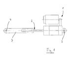
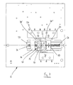
- FIG. 1 shows the basic arrangement of a generic linear actuator. This essentially comprises a drive unit 1 (with a drive motor and a reduction gear) and a driven by the drive unit 1 spindle 2, which is guided in a linearly movable torque tube 3.
- a clevis 4 is used for attachment of a part to be moved (not shown), while the linear drive itself can be fastened by means of a fastening part 5 somewhere.
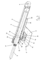
- FIG. 2 shows a 3D partial section through a torque tube 3 with a spindle 2 in the extended position in a linear drive with an inventive end switch unit 6.
- extended position is to be understood as the position in which the spindle 2 is completely turned out of the torque tube 3 (maximum) or moved out.
- retracted position is understood to be the position in which the spindle 2 is completely screwed (or screwed) into the torque tube 3.
- the spindle 2 is driven by a drive shaft 7 of the drive unit 1.
- Drive shaft 7 and spindle 2, however, are not rigidly connected to each other, interposed is a so-called (not shown) wrap spring brake (or more generally: brake device for transmission or deceleration of rotational movements), which is mounted on a toothing 8 of the drive shaft 7.
- the wrap spring brake serves the purpose, on the one hand to enable a transmission of rotational power from the drive shaft 7 to the spindle 2, but on the other hand to brake or prevent a rotational force transmission from the spindle 2 to the drive axle 7.
- the actual transmission of the rotational movement of the spindle 2 to the linear movement of the torque tube 3 is effected by a spindle nut 9 which is fixedly connected to the torque tube 3.
- a spindle thread of the spindle 2 and an internal thread of the spindle nut 9 is not shown.
- a push tube guide 10 is attached at the lower end of the push tube 3. With the push tube guide 10, the torque tube 3 is guided in a fixedly connected to the drive unit 1 casing tube 11. For the sake of clarity, the drive unit 1 with the exception of the drive shaft 7 is not shown here.
- a printed circuit board 12 on which the inventive end switch unit 6 is arranged.
- the latter contains, among other things a first limit switch 13 for detecting the extended position of the push tube 3 and the spindle 2 and a second limit switch 14 for detecting the retracted position of the push tube 3 and the spindle 2.
- a slider 15 and a switching member 16 are also visible.
- the slider 15th is connected via a fixing pin 17 fixed to a shift rod 18.
- the switching member 16 has a guide pin 19 which slides in an elongated guide slot 20 of the shift rod 18. Because of the fixed connection between the shift rod 18 and the slider 15, the latter makes any movement of the shift rod 18 with.
- the switching part 16, however, is displaceable relative to the slider 15. Further explanations on the components and on the function of the limit switch unit cf. the description of FIGS. 5 to 9 ,
- FIG. 2 Furthermore, from the FIG. 2 is a leading edge 21 and a trailing edge 22 of the push tube guide 10.
- the shift rod 18, which in turn is guided between the torque tube 3 and the casing tube 11 is provided at both the front and at the rear end, each with a bend 23.
- the front edge 21 of the push tube guide 10 detects the angling 23 of the shift rod 18 and pulls the latter in the in FIG. 2 shown position. This causes the slide 15 and thus also the switching member 16 are pulled along, whereby the switching part passes into the region of the first limit switch 13, which upon actuation of the first limit switch 13, the extension of the torque tube 3 by turning off the drive unit 1 (electrical switching off the drive motor ) is stopped in the extended position.
- FIG. 3 a 3D partial section through a torque tube 3 with a spindle 2 in the retracted position in a linear drive according to Fig. 2 ,
- the push tube 3 detects the trailing edge 22 of the push tube guide 10, the other bend 23 of the shift rod 18 and pulls the latter in the in FIG. 3 shown position.
- This causes the slider 15 and thus the switching member 16 are pulled along, whereby the switching member 16 enters the region of the second limit switch 14, which upon actuation of the second limit switch 14, the retraction of the torque tube 3 by switching off the drive unit 1 (electrical switching off of Drive motor) is stopped in the retracted position.
- the jacket tube 11 in the FIG. 3 not shown.
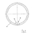
- FIG. 4 shows a cross section through a jacket tube 11.
- the shift rod 18 in the jacket tube 11 and between the jacket tube 11 and not shown here Schubrohr 3 is guided. It can also be seen one of the bends 23 of the shift rod 18th
- wrap spring brakes are an extremely effective and simple means for preventing torque transmission in a direction of rotation in which no torque transmission is allowed, but they also have the disadvantage that, by design, a small rotational path exists until the full braking effect occurs effectively.
- FIG. 1 - 4 described linear drive operated in such a way that a load is lifted via the fork head 4 during extension, this will have the consequence that the load when switching off the drive unit (ie, when the electric drive of the drive motor after the response of the first limit switch 13), the spindle again at a small angle of rotation in the opposite direction Able to turn direction.
- a switching hysteresis is introduced for the limit switch 13, at least for the extended position of the push tube 3.
- the switching hysteresis is introduced equally for both limit switches 13, 14, so that the advantages of the invention can also be utilized with tensile loads. This switching hysteresis is generated in the limit switch unit 6.
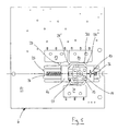
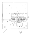
- FIG. 5 shows a plan view of an inventive end switch unit 6 in the retracted position of the spindle 2. All components of the limit switch unit 6 are arranged on the printed circuit board 12.
- the switching part 16 is arranged displaceably relative to the slider 15, both of which are arranged in each case movably on a guide piece 25 and guided linearly. In this case, the slide 15 is supported on both sides with springs 26 relative to the guide piece 25. When the printed circuit board 12 has been removed, this would mean that the slider 15 of the springs 26 in a neutral middle position (see also Fig. 8 and 9 ) is pressed.
- the switching part 16 has a recess 27, in which the slide 15 is reciprocable relative to the switching part 16.
- the switching member 16 is taken from the slider 15.
- the direction of movement of the switching member 16 takes place only when the slider 15 has already covered a path (in the reverse direction) in the recess 27 again. This results in a hysteresis function in the movement.
- the switching part 16 in turn has obliquely applied switching edges 28 ', 28 ", which actuate either a contact pin 29 of the first limit switch 13 or a contact pin 30 of the second limit switch 14 in the maximum deflected positions of the slide 15.
- an emergency limit switch 31 is not relevant in connection with the hysteresis function and is always contacted in normal operation.
- the emergency limit switch 31 is provided in the event that one of the limit switches 13,14 does not work and the deflecting movements of the slider 15 and the switching member 16 are not stopped in time. The switching member 16 then leaves the area in which the contact pin of the emergency limit switch 31 is pressed permanently and as a result, the power supply to the drive motor is completely interrupted.
- FIG. 6 is the spindle 2 relative to the torque tube 3 in the maximum extended position (see also Fig. 2 ), in a position that the torque tube 3 and spindle 2 immediately before the response of the wrap spring brake and thereby caused low return or 'collapse' occupy.
- the slide 15 is in that maximum deflected slide position in which the switching edge 28 'of the switching member 16 contacts the contact pin 29 of the first limit switch 13, whereby the extension movement of the linear drive is stopped in this position.
- the spindle 2 is still opposite the thrust tube 3 in the maximum extended position (see also Fig. 2 ), in a position that the torque tube 3 and spindle 2 immediately after the response of the wrap spring brake and the resulting low return or 'collapse' occupy. Because of the low return of the spindle 2, the shift rod 18 and thus also the slider 15 is shifted slightly in the opposite direction. The switching member 16, however, remains in the position that it is just before the response of the wrap spring brake had reached (cf Fig. 6 ). The first limit switch 13 is still in the contacted state.
- the dimensioning of the recess 27 and the slider 15 must be such that the return or Bremswegeinl the wrap spring brake is not greater than the range of motion, the slider 15 has in the recess 27.
- the desired switching hysteresis is achieved, which prevents the disturbing self-interrupting effect can occur.
- FIGS. 8 and 9 show finally still top views of the limit switch unit in a first and a second neutral position.
- the spindle 2 is located opposite the torque tube 3 neither in the maximum extended nor in the maximum retracted position. This means that neither the front edge 21 nor the trailing edge 22 of the push tube guide 10 touches one or the other bend 23 of the shift rod 18 and thus the position of the shift rod 18 in these intermediate layers does not depend on the mutual position of the thrust tube 3 and spindle 2. Rather, here the slider 15 (with the shift rod 18) is pressed according to the action of the springs 26 in a middle position and the switching part 16 takes in the sequence, the first or second neutral position, depending on which end position the limit switch unit 6 reached the center position ,
Description
Die Erfindung betrifft eine Endschaltereinheit für einen Linearantrieb gemäss den Merkmalen des Patentanspruchs 1.The invention relates to an end switch unit for a linear drive according to the features of patent claim 1.
Linearantriebe mit einem linear bewegbaren Schubrohr und einer im Schubrohr geführten und von einer Antriebseinheit angetriebenen Spindel finden heute weitverbreitete Verwendung. Sie werden häufig verwendet, um Vorrichtungen oder Vorrichtungsteile linear um kurze Strecken zu verschieben oder um Klappen, Deckel und dergleichen zu öffnen und zu schliessen.Linear drives with a linearly movable thrust tube and a guided in the thrust tube and driven by a drive unit spindle are now widely used. They are often used to linearly move devices or device parts short distances or to open and close flaps, lids and the like.
Tendenziell geht die Entwicklung von Linearantrieben dieser Art in eine Richtung, dass versucht wird, immer grössere Wirkungsgrade zu erzielen. Dabei werden Spindeln mit so grossen Gewindesteigungen eingesetzt, dass die Selbsthemmungsgrenzen überschritten werden. In der Folge müssen zwischen den Spindeln und den Antriebsachsen der Antriebseinheit zusätzliche Bauteile, wie beispielsweise Schlingfederbremsen (wrap spring clutches/brakes) eingesetzt werden, um zu verhindern, dass die vom Linearantrieb angehobene Last beim Abstellen des Antriebsmotors in der Antriebseinheit die Spindel wieder in der entgegengesetzten Richtung zu drehen vermag. Derartige Schlingfederbremsen (oder allgemeiner ausgedrückt: Bremsvorrichtungen zur Übertragung oder Abbremsung von Drehbewegungen) sind bereits wohlbekannt. Sie werden wegen ihrer Einfachheit und rein mechanischen Bauweise häufig eingesetzt und sie bewirken, dass eine Drehkraftübertragung nur von der Antriebseinheit (bzw. vom Motor der Antriebseinheit) auf die Spindel, nicht aber von der Spindel auf die Antriebseinheit erfolgen kann.The trend of linear drives of this kind tends to be in a direction that attempts to achieve ever greater efficiencies. Spindles are used with thread pitches that are so large that the self-locking limits are exceeded. As a result, additional components, such as wrap spring clutches / brakes must be used between the spindles and the drive axles of the drive unit to prevent the lifted by the linear drive load when stopping the drive motor in the drive unit, the spindle back in the is able to turn in the opposite direction. Such wrap spring brakes (or, more generally, braking devices for transmission or deceleration of rotational movements) are already well known. They are often used because of their simplicity and purely mechanical design and they cause a torque transmission can only be done by the drive unit (or by the motor of the drive unit) on the spindle, but not from the spindle to the drive unit.
Eine weitere gegenwärtige Entwicklungstendenz geht dahin, dass zur Detektierung der Endstellungen der Spindeln in den Schubrohren (d.h. in den Positionen, in denen die Spindel ganz eingefahren oder ganz ausgefahren ist) Endschalter verwendet werden, die fest mit der Antriebseinheit verbunden und in der Nähe derselben angeordnet sind. Hier geht es grundsätzlich darum, störungs- und verletzungsanfällige bewegliche elektrische Drahtverbindungen oder elektrische Drahtverbindungen, die sich in unmittelbarer Nähe beweglicher Teile befinden, zu vermeiden. Damit kann die Störanfälligkeit der ganzen Vorrichtung beträchtlich reduziert werden.Another current trend is that to detect the end positions of the spindles in the Thrust tubes (ie, in the positions where the spindle is fully retracted or fully extended) limit switches are used which are fixedly connected to and near the drive unit. The basic idea here is to avoid moving electrical wire connections that are susceptible to interference and injury or electrical wire connections that are located in the immediate vicinity of moving parts. Thus, the susceptibility of the whole device can be considerably reduced.
Es sind Linearantriebe bekannt (unter anderem Produkte der Anmelderin), bei denen mittels einer zwischen einem Mantelrohr (auch Führungsrohr genannt) und dem Schubrohr linear verschieblich angeordneten Schaltstange, deren effektive Hin-und Herbewegung durch geeignet angebrachte Mitnehmerteile am Schubrohr nur einen kleinen Bruchteil der gesamten Hin- und Herbewegung des Schubrohres ausmacht, auf Endschalter, die fest in der Nähe der Antriebsvorrichtung angebracht sind, übertragen wird.There are known linear drives (including products of the Applicant), in which by means of a between a jacket tube (also called guide tube) and the torque tube linearly displaceable shift rod whose effective reciprocating motion by suitably mounted driver parts on the torque tube only a small fraction of the total The reciprocating motion of the torque tube is transmitted to limit switches which are fixedly mounted in the vicinity of the drive device.
Die Kombination dieser beiden Entwicklungstendenzen führt allerdings in der Anwendung zu neuen Problemen.However, the combination of these two development tendencies leads to new problems in the application.
Schlingfederbremsen sind zwar ein äusserst wirksames und einfaches in eine Drehachse einsetzbares Mittel zur Verhinderung von Drehkraftübertragungen in eine Drehrichtung, in die keine Drehkraftübertragung erfolgen darf, sie haben aber auch den Nachteil, dass konstruktionsbedingt ein kleiner Drehweg (Drehwinkel) bis zum wirksamen Eintritt der vollen Bremswirkung notwendig ist. Dies hat zur Folge, dass eine vom Linearantrieb angehobene Last beim Abstellen des Antriebsmotors in der Antriebseinheit die Spindel wieder um einen kleinen Drehwinkel in die entgegengesetzten Richtung zu drehen vermag. Dies bewirkt wiederum ein zwar kleines, für denjenigen Endschalter, der zur Detektierung der Spindelposition in der voll ausgefahrenen Stellung verwendet wird, unter Umständen aber folgenreiches 'Zusammensacken' von Spindel und Schubrohr (d.h. es resultiert ein kleines Einfahren der Spindel in das Schubrohr). Wird nämlich eine Dauerkontaktsteuerung für das Ein- und Ausfahren verwendet, was meist der Fall und meist sogar gefordert ist, so genügt das erwähnte Zusammensacken um den elektrischen Kontakt des Endschalters wieder freizugeben, was bedeutet, dass die Information an die Motorsteuerung ergeht, dass das Schubrohr die Endstellung noch nicht erreicht habe. In der Folge kommt es (solange der Dauerkontaktbefehl ansteht) zu einer andauernden Selbstunterbrecherschaltung (d.h. es resultiert ein dauerndes Ein- und Ausschalten des Antriebs), wobei in der Folge die elektrische und mechanische Belastung rasch zu einer Überhitzung des Antriebs und sogar zur Zerstörung von Bauteilen führen kann.Although spring brakes are an extremely effective and simple means for preventing rotational force transmission in a direction of rotation in which no torque transmission is permitted, they also have the disadvantage that, by design, a small rotational path (angle of rotation) until effective entry of the full braking effect necessary is. This has the consequence that a load lifted by the linear drive when turning off the drive motor in the drive unit is able to turn the spindle again by a small angle of rotation in the opposite direction. This, in turn, causes a small limit to that limit switch used to detect the spindle position in the fully extended position but consequential 'slumping' of spindle and torque tube (ie, it results in a small retraction of the spindle in the torque tube). Namely, if a permanent contact control for the extension and retraction used, which is usually the case and usually even required, so the mentioned collapse sufficient to release the electrical contact of the limit switch again, which means that the information goes to the engine control that the torque tube the end position has not yet reached. As a result, (as long as the permanent contact command is present), a continuous self-breaker circuit (ie, permanent power on / off) results, as a result of which the electrical and mechanical load rapidly overheats the drive and even destroys components can lead.
Ziel der Erfindung ist es, eine Endschaltereinheit für einen Linearantrieb anzugeben, bei der die erwähnten Probleme vermieden werden können, bei der aber dennoch die Vorteile einer mit einer Schlingfederbremse bestückten (oder mit einer gleich oder ähnlichen wirkenden Vorrichtung bestückten) und schaltstangenbetätigten Bauweise ausgenützt werden können.The aim of the invention is to provide a limit switch unit for a linear drive, in which the mentioned problems can be avoided, but nevertheless the advantages of a equipped with a wrap spring brake (or equipped with a same or similar acting device) and switching-bar-operated design can be exploited ,
Diese Aufgabe wird durch die Merkmale des Patentanspruchs 1 gelöst.This object is solved by the features of patent claim 1.
Bei einer Endschaltereinheit für einen Linearantrieb mit einer von einem Antriebsmotor angetriebenen Antriebseinheit, einer in einem linear bewegbaren Schubrohr geführten und von der Antriebseinheit angetriebenen Spindel, einer zwischen dem Schubrohr und einem Mantelrohr ebenfalls linear bewegbaren Schaltstange und einer zwischen einer Antriebsachse der Antriebseinheit und der Spindel eingebauten Bremsvorrichtung zur Übertragung oder Abbremsung von Drehbewegungen (z.B. eine Schlingfederbremse, eine Reibungskupplung oder dergleichen), bei der mindestens ein Endschalter der Endschaltereinheit von der Schaltstange betätigbar ist, weist der mindestens eine Endschalter der Endschaltereinheit bezüglich einer Verschiebebewegung der Schaltstange zumindest in einer ausgefahrenen Position des Schubrohrs eine Schalthysterese auf. Die Schalthysterese ist dabei auf einen im wesentlichen von der Schlingfederbremse bedingten Ansprechweg beim Ausschalten des Antriebsmotors abgestimmt.In a limit switch unit for a linear drive with a driven by a drive motor drive unit, guided in a linearly movable thrust tube and driven by the drive unit spindle, a linearly movable between the torque tube and a jacket tube shift rod and between a drive shaft of the drive unit and the spindle built-in Braking device for transmission or deceleration of rotational movements (eg a wrap spring brake, a friction clutch or the like), in which at least one limit switch of the limit switch unit is actuated by the shift rod, which has at least one Limit switch the limit switch unit with respect to a displacement movement of the shift rod, at least in an extended position of the torque tube on a hysteresis. The hysteresis is tuned to a conditional on the mainspring brake response path when switching off the drive motor.
Durch die Einführung der Schalthysterese gelingt es, Selbstunterbrecherschaltungseffekte in den Endlagen des Schubrohrs zu vermeiden.The introduction of the switching hysteresis makes it possible to avoid self-interrupting circuit effects in the end positions of the torque tube.
Wird mit dem erfindungsgemässen Linearantrieb gegen eine Last gedrückt (z.B. das Hochheben eines Fensterdaches), so muss zumindest der Endschalter für die Detektierung der maximal ausgefahrenen Position des Schubrohres mit einer Schalthysterese versehen werden, weil hier der erwähnte störende Selbstunterbrechungseffekt auftreten kann. Bei der Detektierung der maximal eingefahrenen Position braucht es in dieser Situation grundsätzlich keine Schalthysterese, weil hier die Kräfte immer in eine Richtung wirken, in der kein Selbstunterbrechungseffekt auftreten kann.If a load is pressed against a load by the linear drive according to the invention (for example the lifting of a window roof), then at least the limit switch for detecting the maximally extended position of the torque tube must be provided with a switching hysteresis, because here the mentioned disturbing self-interrupting effect can occur. When detecting the maximum retracted position, there is basically no need for a switching hysteresis in this situation, because here the forces always act in a direction in which no self-interrupting effect can occur.
Vorteilhaft wird aber auch die Detektierung der maximal eingefahrenen Position des Schubrohres mit einer Schalthysterese ausgestattet, weil es grundsätzlich auch möglich ist, den Linearantrieb auf Zug zu belasten und dann tritt der störende Selbstunterbrechungseffekt bei der Detektierung der maximal eingefahrenen Position des Schubrohres auf. Mit geringem Mehraufwand lässt sich der Einsatzbereich des Linearantriebs beträchtlich erhöhen.Advantageously, however, the detection of the maximum retracted position of the torque tube is equipped with a switching hysteresis, because it is also possible in principle to load the linear drive to train and then occurs the disturbing self-interrupting effect in the detection of the maximum retracted position of the torque tube. With little extra effort, the range of application of the linear drive can be considerably increased.
Als vorteilhaft erweist es sich auch, wenn zur Detektierung der maximal ausgefahrenen Position des Schubrohrs ein erster Endschalter und zur Detektierung der maximal eingefahrenen Position des Schubrohrs ein zweiter Endschalter verwendet wird. Es können dann zwei gleiche, kostengünstige und einfach gebaute Endschalter verwendet werden. Grundsätzlich sind auch Lösungen möglich, bei denen zur Detektierung der beiden Endlagen des Schubrohrs nur ein einziger Endschalter, beispielsweise ein solcher mit einem Umschaltkontakt, verwendet wird. Ebenso können auch kontaktlos arbeitende Endschalter eingesetzt werden.It proves to be advantageous if a second limit switch is used to detect the maximum extended position of the torque tube, a first limit switch and to detect the maximum retracted position of the torque tube. It can then be two equal, cost effective and easy built limit switches are used. In principle, solutions are also possible in which only one limit switch, for example one with a changeover contact, is used to detect the two end positions of the torque tube. Likewise, contactless limit switches can be used.
Die konstruktive erfindungsgemässe Lösung verwendet vorzugsweise einen gegenüber einem Schieber verschiebbaren Schaltteil, wobei der Schieber mit der Schaltstange verbunden ist und demzufolge deren Bewegungen mitmacht. Der Schieber und das Schaltteil sind beide auf einem Führungsstück linear geführt. Das Schaltteil weist eine Ausnehmung auf, in der der Schieber gegenüber dem Schaltteil hin- und herbewegbar ist, das Schaltteil ist vom Schieber mitnehmbar und die Mitnahmebewegung zufolge der Verschiebebewegung der Schaltstange bewirkt die Schalthysterese. Die Teile sind einfach und leicht herstellbar und sie lassen sich ohne Schwierigkeiten auf einer Platine mit den Endschaltern in einer Weise integrieren, dass Zusammenbau, Einbau, Funktionsüberprüfung und Ersatz besonders einfach sind. Ausserdem ist die Einheit auch als Ersatz zu Einheiten ohne Hysteresefunktion leicht austauschbar.The constructive solution according to the invention preferably uses a shifting part which can be displaced with respect to a slide, wherein the slide is connected to the switching rod and therefore participates in its movements. The slide and the switching part are both guided linearly on a guide piece. The switching member has a recess in which the slider relative to the switching member is reciprocable, the switching member is entrained by the slide and the entrainment movement according to the sliding movement of the shift rod causes the hysteresis. The parts are simple and easy to manufacture, and they can be easily integrated on a circuit board with the limit switches in such a way that assembly, installation, function testing and replacement are particularly easy. In addition, the unit is also easily replaceable as a replacement for units without a hysteresis function.
In den Zeichnungen zeigen:
- Fig. 1
- die grundsätzliche Anordnung eines gattungsgemässen Linearantriebs,
- Fig. 2
- ein 3D-Teilschnitt durch ein Schubrohr mit einer Spindel in ausgefahrener Position bei einem Linear- antrieb mit einer erfindungsgemässen Endschalter- einheit,
- Fig. 3
- ein 3D-Teilschnitt durch ein Schubrohr mit einer Spindel in eingefahrener Position bei einem Linear- antrieb gemäss
Fig. 2 , - Fig. 4
- einen Querschnitt durch ein Mantelrohr,
- Fig. 5
- eine Draufsicht auf eine erfindungsgemässe End- schaltereinheit in der eingefahrenen Position der Spindel,
- Fig. 6
- eine Draufsicht auf eine erfindungsgemässe End- schaltereinheit in der ausgefahrenen Position der Spindel, ohne Rücklauf,
- Fig. 7
- eine Draufsicht auf eine erfindungsgemässe End- schaltereinheit in der ausgefahrenen Position der Spindel, mit Rücklauf,
- Fig. 8
- eine Draufsicht auf eine erfindungsgemässe End- schaltereinheit in einer ersten Neutralstellung, und
- Fig. 9
- eine Draufsicht auf eine erfindungsgemässe End- schaltereinheit in einer zweiten Neutral-Stellung.
- Fig. 1
- the basic arrangement of a generic linear drive,
- Fig. 2
- 3 shows a partial 3D section through a torque tube with a spindle in the extended position in a linear drive with a limit switch unit according to the invention,
- Fig. 3
- a 3D partial section through a torque tube with a spindle in the retracted position in a linear drive according to
Fig. 2 . - Fig. 4
- a cross section through a jacket tube,
- Fig. 5
- a top view of an inventive end switch unit in the retracted position of the spindle,
- Fig. 6
- a top view of an inventive end switch unit in the extended position of the spindle, without return,
- Fig. 7
- a top view of an inventive end switch unit in the extended position of the spindle, with return,
- Fig. 8
- a plan view of an inventive end switch unit in a first neutral position, and
- Fig. 9
- a plan view of an inventive end switch unit in a second neutral position.
Die
Die Spindel 2 wird von einer Antriebsachse 7 der Antriebseinheit 1 angetrieben. Antriebsachse 7 und Spindel 2 sind allerdings nicht starr miteinander verbunden, zwischengeschaltet ist eine sogenannte (nicht dargestellte) Schlingfederbremse (oder allgemeiner ausgedrückt: Bremsvorrichtung zur Übertragung oder Abbremsung von Drehbewegungen), die auf eine Verzahnung 8 der Antriebsachse 7 aufgesetzt ist. Die Schlingfederbremse dient dem Zweck, einerseits eine Drehkraftübertragung von der Antriebsachse 7 auf die Spindel 2 zu ermöglichen, andererseits aber eine Drehkraftübertragung von der Spindel 2 auf die Antriebsachse 7 zu bremsen bzw. zu verhindern.The
Die eigentliche Übertragung der Drehbewegung der Spindel 2 auf die lineare Bewegung des Schubrohrs 3 erfolgt durch eine Spindelmutter 9, die fest mit dem Schubrohr 3 verbunden ist. Der Einfachheit halber ist ein Spindelgewinde der Spindel 2 und ein Innengewinde der Spindelmutter 9 nicht dargestellt.The actual transmission of the rotational movement of the
Am unteren Ende des Schubrohrs 3 ist eine Schubrohrführung 10 angebracht. Mit der Schubrohrführung 10 wird das Schubrohr 3 in einem fest mit der Antriebseinheit 1 verbundenen Mantelrohr 11 geführt. Der besseren Übersicht wegen ist die Antriebseinheit 1 mit Ausnahme der Antriebsachse 7 hier nicht dargestellt.At the lower end of the
Ebenfalls fest verbunden mit der Antriebseinheit 1 ist eine Printplatine 12, auf der die erfindungsgemässe Endschaltereinheit 6 angeordnet ist. Die letztere enthält unter anderem einen ersten Endschalter 13 zur Detektierung der ausgefahrenen Position des Schubrohrs 3 bzw. der Spindel 2 und einen zweiten Endschalter 14 zur Detektierung der eingefahrenen Position des Schubrohrs 3 bzw. der Spindel 2. Ebenfalls sichtbar sind ein Schieber 15 und ein Schaltteil 16. Der Schieber 15 ist über einen Befestigungsstift 17 fest mit einer Schaltstange 18 verbunden. Das Schaltteil 16 hat einen Führungsstift 19, der in einem länglichen Führungsschlitz 20 der Schaltstange 18 gleitet. Wegen der festen Verbindung zwischen der Schaltstange 18 und dem Schieber 15 macht der letztere jede Bewegung der Schaltstange 18 mit. Das Schaltteil 16 hingegen ist gegenüber dem Schieber 15 verschiebbar. Weitere Erläuterungen zu den Bestandteilen und zu der Funktion der Endschaltereinheit vgl. die Beschreibung der
Weiterhin ersichtlich aus der
Die
Die
Die
Schlingfederbremsen sind wie erwähnt ein äusserst wirksames und einfaches Mittel zur Verhinderung von Drehkraftübertragungen in eine Drehrichtung, in die keine Drehkraftübertragung erfolgen darf, sie haben aber auch den Nachteil, dass konstruktionsbedingt ein kleiner Drehweg bis zum wirksamen Eintritt der vollen Bremswirkung existiert. Wird nun beispielsweise der in den
Die
Ergänzend ist noch zu erwähnen, dass die Haftreibung des Schaltteils 16 auf dem Führungsstück 25 natürlich gross genug sein muss, damit das Schaltteil 16 nicht schon allein durch die Rückstellkraft der Kontaktstifte 29,30 auf die Schaltflanken 28',28" verschoben werden kann.In addition, it should be mentioned that the static friction of the switching
In der
Im weiteren ist aus der
In der
In der
Die
Eine weitere Sicherheitsmassnahme ist im übrigen auch noch für den Fall vorgesehen, dass der Befestigungsstift 17, der den Schieber 15 mit der Schaltstange 18 verbindet, bricht. Im Normalbetrieb wird die Bewegung der Schaltstange 18 via den Befestigungsstift 17 auf den Schieber 15 und schliesslich auf das Schaltteil 16 übertragen (vgl. dazu
- 11
- Antriebseinheitdrive unit
- 22
- Spindelspindle
- 33
- Schubrohrtorque tube
- 44
- Gabelkopfclevis
- 55
- Befestigungsteilattachment portion
- 66
- Endschaltereinheitlimit switch
- 77
- Antriebsachsedrive axle
- 88th
- Verzahnunggearing
- 99
- Spindelmutterspindle nut
- 1010
- SchubrohrführungTorque tube guide
- 1111
- Mantelrohr (auch Führungsrohr)Jacket tube (also guide tube)
- 1212
- PrintplatinePrint board
- 1313
- erster Endschalter (für ausgefahrene Position)first limit switch (for extended position)
- 1414
- zweiter Endschalter (für eingefahrene Position)second limit switch (for retracted position)
- 1515
- Schieberpusher
- 1616
- Schaltteilswitching part
- 1717
- Befestigungsstift (des Schiebers)Fixing pin (of the slider)
- 1818
- Schaltstangeshift rod
- 1919
- Führungsstift (des Schaltteils)Guide pin (of the switching part)
- 2020
- Führungsschlitzguide slot
- 2121
- Vorderkante (der Schubrohrführung)Leading edge (the push tube guide)
- 2222
- Hinterkante (der Schubrohrführung)Trailing edge (the thrust tube guide)
- 2323
- Abwinkelung (der Schaltstange)Bend (the shift rod)
- 2424
- nicht verwendetnot used
- 2525
- Führungsstückguide piece
- 2626
- Federfeather
- 2727
- Ausnehmungrecess
- 28', 28"28 ', 28 "
- Schaltflankenswitching edges
- 2929
- Kontaktstift des ersten EndschaltersContact pin of the first limit switch
- 3030
- Kontaktstift des zweiten EndschaltersContact pin of the second limit switch
- 3131
- Not-EndschalterEmergency limit switch
Claims (10)
- A limit switch unit (6) for a linear drive with- a drive unit (1) with a drive motor,- a spindle (2) guided in a linearly movable thrust tube (3) and driven by the drive unit (1) and- an actuating rod (18) likewise linearly movable between the thrust tube (3) and a casing tube (3) and- a braking device installed between a drive axis (7) of the drive unit (1) and the spindle (2) for the transmission or braking of rotary movements,
wherein at least one limit switch of the limit switch unit (6) is able to be actuated by the actuating rod (18),
characterized in that
the at least one limit switch of the limit switch unit has a switching hysteresis with respect to a displacement movement of the actuating rod (18) at least in an extended position of the thrust tube (3), wherein the switching hysteresis is matched to a response path dependent substantially on the braking device for the transmission or braking of rotary movements, on switching off the drive motor. - The limit switch unit according to Claim 1, characterized in that the braking device for the transmission or braking of rotary movements is a wrap spring brake.
- The limit switch unit according to Claim 1 or 2, characterized in that the at least one limit switch of the limit switch unit (6) has a switching hysteresis with respect to a switching position of the actuating rod (18) both in an extended position and also in a retracted position of the thrust tube (3).
- The limit switch unit according to one of Claims 1 to 3, characterized in that the at least one limit switch operates mechanically or in a non-contact manner.
- The limit switch unit according to one of Claims 1 to 4, characterized in that the limit switch unit (6) has a first mechanical limit switch (13) for an extended position of the thrust tube (3) and a second mechanical limit switch (14) for a retracted position of the thrust tube (3).
- The limit switch unit according to Claim 5, characterized in that the first and the second limit switches (13, 14) are able to be actuated by a switching part (16) which is displaceable with respect to a slider (15), and the slider (15) is connected to the actuating rod (18).
- The limit switch unit according to Claim 6, characterized in that the slider (15) and the switching part (16) which is displaceable with respect to the slider (15) are guided linearly by a guide piece (25), and the slider (15) is supported on both sides with respect to the guide piece (25) by springs (26).
- The limit switch unit according to Claim 6 or 7, characterized in that the switching part (16) has a recess (27) in which the slider (16) is movable to and fro with respect to the switching part (16), the switching part (16) is able to be entrained by the slider (15) and the entrainment movement brings about the switching hysteresis as a result of the displacement movement of the actuating rod.
- The limit switch unit according to Claim 6, characterized in that the first and the second limit switches (13, 14) of the limit switch unit is able to be actuated via the switching part (16) and the slider (15) and a fastening pin (17) connecting the slider (15) with the actuating rod (18), and that in addition a guide pin (19) is arranged on the switching part (16), via which guide pin the linear drive is able to be switched off on failure of the fastening pin.
- The limit switch unit according to Claim 5, characterized in that on failure of the first and the second limit switch (13, 14), the linear drive is able to be switched off by means of an emergency limit switch (31).
Applications Claiming Priority (2)
| Application Number | Priority Date | Filing Date | Title |
|---|---|---|---|
| CH19242002 | 2002-11-15 | ||
| CH19242002 | 2002-11-15 |
Publications (2)
| Publication Number | Publication Date |
|---|---|
| EP1420504A1 EP1420504A1 (en) | 2004-05-19 |
| EP1420504B1 true EP1420504B1 (en) | 2012-06-13 |
Family
ID=32111468
Family Applications (1)
| Application Number | Title | Priority Date | Filing Date |
|---|---|---|---|
| EP03405802A Expired - Lifetime EP1420504B1 (en) | 2002-11-15 | 2003-11-10 | Limit switch for a linear drive |
Country Status (1)
| Country | Link |
|---|---|
| EP (1) | EP1420504B1 (en) |
Families Citing this family (7)
| Publication number | Priority date | Publication date | Assignee | Title |
|---|---|---|---|---|
| US7992460B2 (en) | 2006-09-09 | 2011-08-09 | Stabilus Gmbh | Drive device |
| WO2009155922A1 (en) * | 2008-06-27 | 2009-12-30 | Linak A/S | Linear actuator |
| RU2582744C2 (en) | 2010-12-21 | 2016-04-27 | Линак А/С | Linear drive |
| CN102647048B (en) * | 2011-02-17 | 2014-05-07 | 第一传动科技股份有限公司 | Stroke limit device used for linear actuator and take-up mechanism thereof |
| US8714039B2 (en) | 2011-04-09 | 2014-05-06 | Timotion Technology Co., Ltd. | Stroke-restricting device of linear actuator and wire-reeling mechanism thereof |
| DE102011017170B4 (en) * | 2011-04-15 | 2017-05-24 | Timotion Technology Co., Ltd. | Hubbegrenzende device of a linear drive |
| CN113581680B (en) * | 2021-08-13 | 2022-11-01 | 上海海洋大学 | Flexible bidirectional limiting mechanism for bin door |
Citations (1)
| Publication number | Priority date | Publication date | Assignee | Title |
|---|---|---|---|---|
| GB643863A (en) * | 1946-07-01 | 1950-09-27 | Bendix Aviat Corp | Improvements in or relating to linearly extending actuators |
Family Cites Families (4)
| Publication number | Priority date | Publication date | Assignee | Title |
|---|---|---|---|---|
| US3682283A (en) | 1970-03-02 | 1972-08-08 | Mitumasa Sato | Motor-driven actuator and safety overload mechanism therefor |
| JP2539688B2 (en) | 1989-11-02 | 1996-10-02 | 東芝機械株式会社 | Rapid traverse speed control method for moving body |
| GB2263465B (en) * | 1992-01-09 | 1995-05-31 | Link Miles Ltd | Electrically powered actuator |
| DK4094A (en) * | 1994-01-10 | 1995-07-11 | Linak As | Linear actuator |
-
2003
- 2003-11-10 EP EP03405802A patent/EP1420504B1/en not_active Expired - Lifetime
Patent Citations (1)
| Publication number | Priority date | Publication date | Assignee | Title |
|---|---|---|---|---|
| GB643863A (en) * | 1946-07-01 | 1950-09-27 | Bendix Aviat Corp | Improvements in or relating to linearly extending actuators |
Also Published As
| Publication number | Publication date |
|---|---|
| EP1420504A1 (en) | 2004-05-19 |
Similar Documents
| Publication | Publication Date | Title |
|---|---|---|
| EP1390638B1 (en) | Electromechanical brake with zero backlash actuation | |
| EP3691943B1 (en) | Mechanical brake actuator | |
| DE10102685B4 (en) | Actuating mechanism with force sensor for one brake | |
| DE3309427C2 (en) | ||
| DE10030409A1 (en) | Adjustment drive has deployed piston rod position limit end switch in contact with tube if drive has not reached end position, and retracted position switch contacting nut in other end position | |
| DE102016207237A1 (en) | Actuator for actuating a clutch of a vehicle | |
| DE60027380T2 (en) | Automatic switch-off device | |
| DE102011108977B4 (en) | Actuator, in particular for a vehicle seat | |
| EP1420504B1 (en) | Limit switch for a linear drive | |
| DE10212879A1 (en) | Actuation mechanism for a parking brake | |
| DE102004002114B4 (en) | Accelerator pedal unit with force jump element | |
| DE102009022404A1 (en) | spindle drive | |
| EP3165419B1 (en) | Overrun brake for a trailer | |
| EP1619413A2 (en) | Actuator | |
| DE102014009131A1 (en) | Electromechanical brake device | |
| DE19509568C1 (en) | Gear, especially worm gear | |
| EP1619414A2 (en) | Actuator | |
| DE4141460A1 (en) | Pressure driven ram with piston and tubular piston rod - has sliding screw-bush placed axially beside ball-screw-bush, connected together by clutch pins | |
| EP3187387B1 (en) | Parking brake | |
| DE10152423C2 (en) | disc brake | |
| EP1426641A1 (en) | Clutch actuator device | |
| DE4403740C2 (en) | Electromechanical, at least two-stage application device for friction brakes | |
| DE2156736B2 (en) | Foot brake pedal for motor vehicle - has mechanically connected control switch for disconnecting drive in emergency | |
| DE102004049796B4 (en) | linear actuator | |
| DE10245363A1 (en) | Switchable stabilizer for motor vehicles |
Legal Events
| Date | Code | Title | Description |
|---|---|---|---|
| PUAI | Public reference made under article 153(3) epc to a published international application that has entered the european phase |
Free format text: ORIGINAL CODE: 0009012 |
|
| AK | Designated contracting states |
Kind code of ref document: A1 Designated state(s): AT BE BG CH CY CZ DE DK EE ES FI FR GB GR HU IE IT LI LU MC NL PT RO SE SI SK TR |
|
| AX | Request for extension of the european patent |
Extension state: AL LT LV MK |
|
| 17P | Request for examination filed |
Effective date: 20040921 |
|
| AKX | Designation fees paid |
Designated state(s): AT BE BG CH CY CZ DE DK EE ES FI FR GB GR HU IE IT LI LU MC NL PT RO SE SI SK TR |
|
| 17Q | First examination report despatched |
Effective date: 20090310 |
|
| GRAP | Despatch of communication of intention to grant a patent |
Free format text: ORIGINAL CODE: EPIDOSNIGR1 |
|
| RIC1 | Information provided on ipc code assigned before grant |
Ipc: H02K 7/06 20060101AFI20120110BHEP Ipc: F16H 25/20 20060101ALI20120110BHEP Ipc: F16H 25/24 20060101ALI20120110BHEP Ipc: H02K 11/00 20060101ALI20120110BHEP |
|
| GRAS | Grant fee paid |
Free format text: ORIGINAL CODE: EPIDOSNIGR3 |
|
| GRAA | (expected) grant |
Free format text: ORIGINAL CODE: 0009210 |
|
| AK | Designated contracting states |
Kind code of ref document: B1 Designated state(s): AT BE BG CH CY CZ DE DK EE ES FI FR GB GR HU IE IT LI LU MC NL PT RO SE SI SK TR |
|
| REG | Reference to a national code |
Ref country code: GB Ref legal event code: FG4D Free format text: NOT ENGLISH |
|
| REG | Reference to a national code |
Ref country code: CH Ref legal event code: EP Ref country code: AT Ref legal event code: REF Ref document number: 562364 Country of ref document: AT Kind code of ref document: T Effective date: 20120615 |
|
| REG | Reference to a national code |
Ref country code: DE Ref legal event code: R082 Ref document number: 50314371 Country of ref document: DE Representative=s name: KOHL, THOMAS, DIPL.-ING. UNIV., DE Ref country code: DE Ref legal event code: R082 Ref document number: 50314371 Country of ref document: DE Representative=s name: THOMAS KOHL, DE |
|
| REG | Reference to a national code |
Ref country code: IE Ref legal event code: FG4D Free format text: LANGUAGE OF EP DOCUMENT: GERMAN |
|
| REG | Reference to a national code |
Ref country code: DE Ref legal event code: R096 Ref document number: 50314371 Country of ref document: DE Effective date: 20120809 |
|
| REG | Reference to a national code |
Ref country code: NL Ref legal event code: VDEP Effective date: 20120613 |
|
| PG25 | Lapsed in a contracting state [announced via postgrant information from national office to epo] |
Ref country code: SE Free format text: LAPSE BECAUSE OF FAILURE TO SUBMIT A TRANSLATION OF THE DESCRIPTION OR TO PAY THE FEE WITHIN THE PRESCRIBED TIME-LIMIT Effective date: 20120613 Ref country code: CY Free format text: LAPSE BECAUSE OF FAILURE TO SUBMIT A TRANSLATION OF THE DESCRIPTION OR TO PAY THE FEE WITHIN THE PRESCRIBED TIME-LIMIT Effective date: 20120613 Ref country code: FI Free format text: LAPSE BECAUSE OF FAILURE TO SUBMIT A TRANSLATION OF THE DESCRIPTION OR TO PAY THE FEE WITHIN THE PRESCRIBED TIME-LIMIT Effective date: 20120613 |
|
| PG25 | Lapsed in a contracting state [announced via postgrant information from national office to epo] |
Ref country code: GR Free format text: LAPSE BECAUSE OF FAILURE TO SUBMIT A TRANSLATION OF THE DESCRIPTION OR TO PAY THE FEE WITHIN THE PRESCRIBED TIME-LIMIT Effective date: 20120914 Ref country code: SI Free format text: LAPSE BECAUSE OF FAILURE TO SUBMIT A TRANSLATION OF THE DESCRIPTION OR TO PAY THE FEE WITHIN THE PRESCRIBED TIME-LIMIT Effective date: 20120613 |
|
| PG25 | Lapsed in a contracting state [announced via postgrant information from national office to epo] |
Ref country code: CZ Free format text: LAPSE BECAUSE OF FAILURE TO SUBMIT A TRANSLATION OF THE DESCRIPTION OR TO PAY THE FEE WITHIN THE PRESCRIBED TIME-LIMIT Effective date: 20120613 Ref country code: EE Free format text: LAPSE BECAUSE OF FAILURE TO SUBMIT A TRANSLATION OF THE DESCRIPTION OR TO PAY THE FEE WITHIN THE PRESCRIBED TIME-LIMIT Effective date: 20120613 Ref country code: RO Free format text: LAPSE BECAUSE OF FAILURE TO SUBMIT A TRANSLATION OF THE DESCRIPTION OR TO PAY THE FEE WITHIN THE PRESCRIBED TIME-LIMIT Effective date: 20120613 Ref country code: SK Free format text: LAPSE BECAUSE OF FAILURE TO SUBMIT A TRANSLATION OF THE DESCRIPTION OR TO PAY THE FEE WITHIN THE PRESCRIBED TIME-LIMIT Effective date: 20120613 |
|
| PG25 | Lapsed in a contracting state [announced via postgrant information from national office to epo] |
Ref country code: IT Free format text: LAPSE BECAUSE OF FAILURE TO SUBMIT A TRANSLATION OF THE DESCRIPTION OR TO PAY THE FEE WITHIN THE PRESCRIBED TIME-LIMIT Effective date: 20120613 Ref country code: PT Free format text: LAPSE BECAUSE OF FAILURE TO SUBMIT A TRANSLATION OF THE DESCRIPTION OR TO PAY THE FEE WITHIN THE PRESCRIBED TIME-LIMIT Effective date: 20121015 |
|
| PG25 | Lapsed in a contracting state [announced via postgrant information from national office to epo] |
Ref country code: NL Free format text: LAPSE BECAUSE OF FAILURE TO SUBMIT A TRANSLATION OF THE DESCRIPTION OR TO PAY THE FEE WITHIN THE PRESCRIBED TIME-LIMIT Effective date: 20120613 |
|
| PLBE | No opposition filed within time limit |
Free format text: ORIGINAL CODE: 0009261 |
|
| STAA | Information on the status of an ep patent application or granted ep patent |
Free format text: STATUS: NO OPPOSITION FILED WITHIN TIME LIMIT |
|
| PG25 | Lapsed in a contracting state [announced via postgrant information from national office to epo] |
Ref country code: ES Free format text: LAPSE BECAUSE OF FAILURE TO SUBMIT A TRANSLATION OF THE DESCRIPTION OR TO PAY THE FEE WITHIN THE PRESCRIBED TIME-LIMIT Effective date: 20120924 Ref country code: DK Free format text: LAPSE BECAUSE OF FAILURE TO SUBMIT A TRANSLATION OF THE DESCRIPTION OR TO PAY THE FEE WITHIN THE PRESCRIBED TIME-LIMIT Effective date: 20120613 |
|
| 26N | No opposition filed |
Effective date: 20130314 |
|
| BERE | Be: lapsed |
Owner name: A.B. SKF Effective date: 20121130 |
|
| REG | Reference to a national code |
Ref country code: CH Ref legal event code: PL |
|
| REG | Reference to a national code |
Ref country code: DE Ref legal event code: R097 Ref document number: 50314371 Country of ref document: DE Effective date: 20130314 |
|
| GBPC | Gb: european patent ceased through non-payment of renewal fee |
Effective date: 20121110 |
|
| PG25 | Lapsed in a contracting state [announced via postgrant information from national office to epo] |
Ref country code: CH Free format text: LAPSE BECAUSE OF NON-PAYMENT OF DUE FEES Effective date: 20121130 Ref country code: LI Free format text: LAPSE BECAUSE OF NON-PAYMENT OF DUE FEES Effective date: 20121130 Ref country code: BG Free format text: LAPSE BECAUSE OF FAILURE TO SUBMIT A TRANSLATION OF THE DESCRIPTION OR TO PAY THE FEE WITHIN THE PRESCRIBED TIME-LIMIT Effective date: 20120913 |
|
| REG | Reference to a national code |
Ref country code: IE Ref legal event code: MM4A |
|
| REG | Reference to a national code |
Ref country code: FR Ref legal event code: ST Effective date: 20130731 |
|
| PG25 | Lapsed in a contracting state [announced via postgrant information from national office to epo] |
Ref country code: BE Free format text: LAPSE BECAUSE OF NON-PAYMENT OF DUE FEES Effective date: 20121130 |
|
| PG25 | Lapsed in a contracting state [announced via postgrant information from national office to epo] |
Ref country code: IE Free format text: LAPSE BECAUSE OF NON-PAYMENT OF DUE FEES Effective date: 20121110 |
|
| PG25 | Lapsed in a contracting state [announced via postgrant information from national office to epo] |
Ref country code: GB Free format text: LAPSE BECAUSE OF NON-PAYMENT OF DUE FEES Effective date: 20121110 Ref country code: FR Free format text: LAPSE BECAUSE OF NON-PAYMENT OF DUE FEES Effective date: 20121130 |
|
| REG | Reference to a national code |
Ref country code: AT Ref legal event code: MM01 Ref document number: 562364 Country of ref document: AT Kind code of ref document: T Effective date: 20121130 |
|
| PG25 | Lapsed in a contracting state [announced via postgrant information from national office to epo] |
Ref country code: AT Free format text: LAPSE BECAUSE OF NON-PAYMENT OF DUE FEES Effective date: 20121130 |
|
| PG25 | Lapsed in a contracting state [announced via postgrant information from national office to epo] |
Ref country code: TR Free format text: LAPSE BECAUSE OF FAILURE TO SUBMIT A TRANSLATION OF THE DESCRIPTION OR TO PAY THE FEE WITHIN THE PRESCRIBED TIME-LIMIT Effective date: 20120613 Ref country code: MC Free format text: LAPSE BECAUSE OF NON-PAYMENT OF DUE FEES Effective date: 20121130 |
|
| PG25 | Lapsed in a contracting state [announced via postgrant information from national office to epo] |
Ref country code: LU Free format text: LAPSE BECAUSE OF NON-PAYMENT OF DUE FEES Effective date: 20121110 |
|
| PG25 | Lapsed in a contracting state [announced via postgrant information from national office to epo] |
Ref country code: HU Free format text: LAPSE BECAUSE OF FAILURE TO SUBMIT A TRANSLATION OF THE DESCRIPTION OR TO PAY THE FEE WITHIN THE PRESCRIBED TIME-LIMIT Effective date: 20031110 |
|
| REG | Reference to a national code |
Ref country code: DE Ref legal event code: R082 Ref document number: 50314371 Country of ref document: DE Representative=s name: HEYERHOFF GEIGER GMBH & CO. KG, DE Ref country code: DE Ref legal event code: R082 Ref document number: 50314371 Country of ref document: DE Representative=s name: HEYERHOFF GEIGER & PARTNER PATENTANWAELTE PART, DE |
|
| REG | Reference to a national code |
Ref country code: DE Ref legal event code: R082 Ref document number: 50314371 Country of ref document: DE Representative=s name: HEYERHOFF GEIGER & PARTNER PATENTANWAELTE PART, DE Ref country code: DE Ref legal event code: R081 Ref document number: 50314371 Country of ref document: DE Owner name: EWELLIX AB, SE Free format text: FORMER OWNER: AB SKF, GOETEBORG, SE |
|
| PGFP | Annual fee paid to national office [announced via postgrant information from national office to epo] |
Ref country code: DE Payment date: 20221123 Year of fee payment: 20 |
|
| P01 | Opt-out of the competence of the unified patent court (upc) registered |
Effective date: 20230514 |
|
| REG | Reference to a national code |
Ref country code: DE Ref legal event code: R071 Ref document number: 50314371 Country of ref document: DE |