EP1420331A1 - Miniaturcomputer und Verfahren zur Kühlung - Google Patents
Miniaturcomputer und Verfahren zur Kühlung Download PDFInfo
- Publication number
- EP1420331A1 EP1420331A1 EP02257852A EP02257852A EP1420331A1 EP 1420331 A1 EP1420331 A1 EP 1420331A1 EP 02257852 A EP02257852 A EP 02257852A EP 02257852 A EP02257852 A EP 02257852A EP 1420331 A1 EP1420331 A1 EP 1420331A1
- Authority
- EP
- European Patent Office
- Prior art keywords
- heat
- air
- fan
- dissipating
- motherboard
- Prior art date
- Legal status (The legal status is an assumption and is not a legal conclusion. Google has not performed a legal analysis and makes no representation as to the accuracy of the status listed.)
- Withdrawn
Links
Images


Classifications
-
- G—PHYSICS
- G06—COMPUTING OR CALCULATING; COUNTING
- G06F—ELECTRIC DIGITAL DATA PROCESSING
- G06F1/00—Details not covered by groups G06F3/00 - G06F13/00 and G06F21/00
- G06F1/16—Constructional details or arrangements
- G06F1/20—Cooling means
Definitions
- the present invention relates to a miniaturized allocation of a computer and a heat-dissipating method thereof, more particularly, a miniaturized computer employing stackable motherboards and separable heat-dissipating mechanism, and a heat-dissipating method for the miniaturized computer by utilizing a separable heat-dissipating mechanism and an air-channeling device.
- a conventional computer utilizes a plane-surface single-plate motherboard, thus occupying large plane surface area.
- multi-board stackable allocation including a motherboard, a low-speed interface, a high-speed interface and an input/output interface has already been disclosed, such as US Patent No. 6,229,700 and the miniaturized computer manufactured by Saint Song Corp. basing upon the foregoing patent.
- the present invention employs multi-board stackable allocation including a motherboard, a low-speed interface, a high-speed interface and an input/output interface, thus drastically reducing the area of single motherboard; also the separable heat-dissipating mechanism is employed, thus lowering half of the height of the motherboard. Therefore the total space required by the present invention is far less than that for the conventional computer host, and the space thereof is only half of that for the miniaturized computer manufactured basing upon the foregoing US Patent No. 6,229,700.
- the air-channeling device is utilized in accordance with the separable heat-dissipating mechanism, such design totally solves the heat-dissipating problem.
- One object of the present invention is to provide with a miniaturized computer.
- Another object of the present invention is to provide with a heat-dissipating method for a miniaturized computer.
- Yet another object of the present invention is to provide with a miniaturized computer employing a stackable boards in accordance with a separableheat-dissipating mechanism.
- Yet another object of the present invention is to provide with a miniaturized computer employing a stackable boards in accordance with an air-channeling device.
- Yet another object of the present invention is to provide with a miniaturized computer employing an air-channeling device in accordance with a separable heat-dissipating mechanism.
- Yet another object of the present invention is to provide with a miniaturized. computer formed by both stackable motherboard and separable heat-dissipating mechanism in accordance with an air-channeling device.
- a miniaturized computer of the present invention comprising:
- the shape of the computer housing is identical to that of the common computer housing, only with the size thereof being altered to be in accordance with the size of the miniaturized computer.
- the motherboard can be any conventional motherboard commonly utilized in miniaturized computers, for example, the motherboard comprises a CPU, a north bridge chipset, a south bridge chipset, a memory, a USB, a 13994 and main controllers, etc.
- the low-speed interface for example, comprises output ports for a CD-ROM, a printer, a keyboard, a mouse, an audio-video interface and a wireless interface.
- the high-speed interface for example, comprises output ports for a hard disk, a TV output, a UBS, a 13994 and audio effect.
- the input/output interface for example, comprises output ports for a power source control, an amplifier, a UBS, a 13994 and sound effect.
- the heat-dissipating device can be any conventional computer heat-dissipating device such as aluminum extrusion, die casting and folding types of fins.
- the fans can be any conventional computer fans or similar thereto.
- the air-channeling device of the present invention can be any conventional ring-pole shape or ring-pole shape having one or more indentations substantially caused by peripheral surroundings, such as -type cover (in accordance with the motherboard to form substantially ring-pole shape) or motherboard formed as shape or L shape cover(in accordance with the motherboard and the side board of the computer housing to form substantially ring-pole shape).
- the heat-dissipating mechanism formed by both the fan and the heat-dissipating device can be either vertically stackable or separable, preferably separable.
- the separable heat-dissipating mechanism it is preferable for the heat-dissipating device to be mounted on a primary heat source (such as CPU), and for the fan to be mounted on a secondary heat source (such as north bridge chipset).
- a heat-conducting device can be disposed between the fan and the secondary heat source, such as heat-conductive metal plates, so as to further improve the heat-dissipating effect for the secondary heat source.
- the fan can be any kind of conventional fans utilized in computers, preferably fans blowing sideways or more preferably fans blowing sideways with a single air-blowing outlet. It is preferable for the heat-dissipating device to form a plurality of parallel heat-dissipating fins. Moreover, as the fan blowing sideways with a single air-blowing outlet and parallel heat-dissipating fins are employed, an air-blowing direction of the single air-blowing outlet of the fan blowing sideways and the direction of the parallel heat-dissipating fins are substantially identical or parallel to the air-channeling direction of the air-channeling device.
- a miniaturized computer comprising:
- the miniaturized computer can further include an air-channeling device as described previously.
- a heat-dissipating method for a miniaturized computer of the present invention comprising the following steps:
- An air outlet can be disposed on the foregoing computer housing at the end of the air-channeling direction of the air-channeling device, so as to strengthen the air-channeling and heat-dissipating effects.
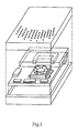
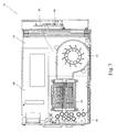
- Figure 1 shows the conventional miniaturized computer, yet there are two drawbacks found in the foregoing miniaturized computer, first the conventional heat-dissipating mechanism by stacking the fan and the heat-dissipating fins is employed, therefore the thickness of the stackable boards cannot be lower, thus requiring larger area; secondly, the conventional heat-dissipating mechanism is simply employed, therefore the problem of heat energy concentration caused by computer miniaturization cannot be solved.
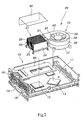
- the preferred embodiments of the present invention are shown in Figures 2, 3, 4, 5, 6, 7 and 8.
- the present invention provides with a miniaturized computer comprising a motherboard 11, a low-speed interface 70, a high-speed interface 60, a computer housing 14 and an input/output interface 80, wherein the low-speed interface 70, the high-speed interface 60 and the input-output interface 80 are all connected to the motherboard 11.
- the motherboard 11 includes a heat-dissipating mechanism 20, more particularly, a heat-dissipating mechanism 20 mounted on the motherboard 11 within the computer host 10 for assisting two heat sources 12 and 13 in dissipating heat generated therefrom, wherein the primary heat source 12 is that like a CPU, whereas the secondary heat source 13 is that like a north bridge chipset which generates lower temperature than that of the primary heat source 12.
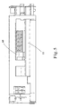
- the heat-dissipating mechanism 20 comprises a heat-dissipating device 21 and a fan 22, wherein the heat-dissipating device 21 can be any type of aluminum extrusion, die casting and folding without limitation.
- the heat-dissipating device 21, made of effective heat-conducting material such as copper or aluminum, comprises a main body 23 having a plurality of fins 24 formed thereon, with fin grooves 25 between the fins 24 so as to expedite the flow of air.
- the bottom surface of the main body 23 of the heat-dissipating device 21 is attached to the heat surface of the primary heat source 12, and a proper fastening means 26 can be mounted for fastening the heat-dissipating device 21 stably on the surface of the primary heat source 12, so as to enable the heat-dissipating device 21 to assist the primary heat source 12 in dissipating heat.
- the fan 22, disposed on the side of the heat-dissipating device 21, is in the identical direction or parallel to the fins 24.
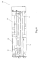
- the fan 22 comprises a lower cover 27, an upper cover 28 and a fan-blade body 29, wherein the lower cover 27 is made of effective heat-conducting material such as copper or aluminum, and the upper cover 28 can be made of metal or plastic,
- the upper cover 28 is mounted on top of the lower cover 27 to be integrally jointed with one another by engagement or utilizing screws to fasten both together, thus forming a housing 40 for the fan 22.
- An air inlet 30 is mounted on the top of the housing 40 (namely the top of the upper cover 28), and a protruding air outlet 31 is disposed on one side of the housing 40 (namely one side of both the upper cover 27 and the lower cover 28).
- a containing chamber 32 disposed within the housing 40, is to link with both the air inlet 30 and the air outlet 31.
- the bottom surface of the lower cover 27 of the fan 22 is attached to the surface of the secondary heat source 13, and the lower cover 27 of the fan 22 is adequately fastened to the motherboard 11, so as to cause the direction of the air outlet 32 to be identical or parallel to the heat-dissipating direction of the heat-dissipating device 21.
- the fan-blade body 29 is pivotally disposed within the containing chamber 32 of the housing 40, and a motor is disposed between the fan-blade body 29 and the housing 40 (not shown in drawings), so as to cause the fan-blade body 29 to rotate, during which air is drawn in through the air inlet 30 and discharged through the air outlet 31, so as to enable the fan to become a fan blowing sideways,
- An air-channeling device 50 covers the periphery of both the heat-dissipating device 21 and the fan 22 so as to enable airflow from the fan 22 to blow off and thus discharge heat energy accumulated by the heat-dissipating device 21 in the air-channeling direction of the air-channeling device 50, thus the heat-dissipating assembly structure of the present invention is formed thereby.
- the heat-dissipating structure can be disposed within the computer host 10, and the heat-dissipating device 21 and the fan 22 is designed to be separate to each other, so as to enable the heat-dissipating device 21 and the fan 22 respectively attach to the primary heat source 12 and the secondary heat source 13.
- Heat energy generated by the secondary heat source 13 such as the north bridge chipset with lesser amount of heat generated can be transferred to the lower cover 27 of the fan 22, and with the rotation of the fan-blade body 29, cold air is to be introduced through the air inlet 30 on the top of the housing 40 of the fan 22, and warm air is to be discharged through the air outlet 31 on one side of the housing 40 of the fan 22, thus dissipating the heat generated by the secondary heat source 13.
- Heat energy generated during operation of the primary heat source 12 such as CPU can be transferred to the heat-dissipating device 21, whereon a plurality of fins 24 are formed for increasing the heat-dissipating area so as to cope with the primary heat source 12 having higher rate of heat generation, thus the heat-dissipating efficiency can be improved.
- warm air discharged through the air outlet 31 on one side of the housing 40 can dissipate heat for the primary heat source 12 and the heat-dissipating device 21 which are both placed on the outside of the air outlet 31 having high temperature, and warm air discharged through the air outlet 31 of the housing 40 can flow through the fin groove 25, and then hot air is to be discharged out through the air-discharging outlet 15 previously mounted on the side surface of the computer housing 14 of the computer host 10.
- the shape of the air-discharging outlet 15 is not limited and can be varied according to different needs.
- proper air inlet 16 can also be mounted on the computer housing 14 of the computer host 10, so as to draw cold air into the computer host 10.
- the shape of the air inlet 16 is not limited and can be varied according to different needs.
- Another fan (not shown in drawings) can be mounted on the air inlet 16 so as to forcibly draw in cold air, thus achieving better air circulation effect.
- the lower cover 27 of the fan 22 of the present invention provides with heat-conducting and heat-dissipating effect, and the fan is designed to slantly dissipate heat, thus wind pressure shall be less, and heat energy can be swiftly discharged, so as to acquire better heat-dissipating efficiency and greater heat-dissipating capacity can be achieved.
- the computer heat-dissipating structure of the present invention is designed to be separate, so as to dissipate heat generated from both heat sources 12 and 13 simultaneously, thus better heat-dissipating efficiency can be achieved. With such simple structural design, the production cost shall not be increased and more space is not needed.
- the fan 22 of the present invention is disposed on the side of the heat-dissipating device 21, thus the overall height of the whole heat-dissipating mechanism 20 can be lowered, enabling the present invention to be applicable to computers having height limit.
- the present invention actually discharges the high-temperature air generated by heat sources in a computer host such as the CPU and the north bridge chipset slantly from the computer host, and with external cold air drawn by the air inlet 16 into the computer host 10, better air circulation can be achieved.
- an air-channeling device 50 covers the periphery of both the heat-dissipating device 21 and the fan 22, enabling airflow generated by the fan 22 to dissipate heat energy accumulated in the heat-dissipating device 21 in the air-channeling direction of the air-channeling device 50, thus improving upon the drawback of ineffective heat-dissipating condition within computer hosts and acquire better heat-dissipating efficiency.
Landscapes
- Engineering & Computer Science (AREA)
- Theoretical Computer Science (AREA)
- Human Computer Interaction (AREA)
- Physics & Mathematics (AREA)
- General Engineering & Computer Science (AREA)
- General Physics & Mathematics (AREA)
- Cooling Or The Like Of Electrical Apparatus (AREA)
Priority Applications (3)
| Application Number | Priority Date | Filing Date | Title |
|---|---|---|---|
| EP02257852A EP1420331A1 (de) | 2002-11-14 | 2002-11-14 | Miniaturcomputer und Verfahren zur Kühlung |
| US10/294,580 US20040095719A1 (en) | 2002-11-14 | 2002-11-15 | Miniature computer and method for heat sink |
| JP2002369036A JP2004171501A (ja) | 2002-11-14 | 2002-11-15 | 小型コンピュータおよび放熱方法 |
Applications Claiming Priority (3)
| Application Number | Priority Date | Filing Date | Title |
|---|---|---|---|
| EP02257852A EP1420331A1 (de) | 2002-11-14 | 2002-11-14 | Miniaturcomputer und Verfahren zur Kühlung |
| US10/294,580 US20040095719A1 (en) | 2002-11-14 | 2002-11-15 | Miniature computer and method for heat sink |
| JP2002369036A JP2004171501A (ja) | 2002-11-14 | 2002-11-15 | 小型コンピュータおよび放熱方法 |
Publications (1)
| Publication Number | Publication Date |
|---|---|
| EP1420331A1 true EP1420331A1 (de) | 2004-05-19 |
Family
ID=32853960
Family Applications (1)
| Application Number | Title | Priority Date | Filing Date |
|---|---|---|---|
| EP02257852A Withdrawn EP1420331A1 (de) | 2002-11-14 | 2002-11-14 | Miniaturcomputer und Verfahren zur Kühlung |
Country Status (3)
| Country | Link |
|---|---|
| US (1) | US20040095719A1 (de) |
| EP (1) | EP1420331A1 (de) |
| JP (1) | JP2004171501A (de) |
Cited By (1)
| Publication number | Priority date | Publication date | Assignee | Title |
|---|---|---|---|---|
| CN116033730A (zh) * | 2023-03-27 | 2023-04-28 | 之江实验室 | 机箱及飞行设备 |
Families Citing this family (10)
| Publication number | Priority date | Publication date | Assignee | Title |
|---|---|---|---|---|
| US7447039B2 (en) * | 2006-10-17 | 2008-11-04 | Hon Hai Precision Industry Co., Ltd. | Motherboard configured to minimize or prevent damage to a chip thereon |
| TWM362433U (en) * | 2008-10-29 | 2009-08-01 | Asia Optical Co Inc | Light source heat-dissipating blocks for projector |
| CN101965116A (zh) * | 2009-07-21 | 2011-02-02 | 富准精密工业(深圳)有限公司 | 散热模组 |
| CN103049045B (zh) * | 2011-10-17 | 2015-11-18 | 华硕电脑股份有限公司 | 主机板模块及应用该主机板模块的电子装置 |
| US9069535B2 (en) | 2013-06-07 | 2015-06-30 | Apple Inc. | Computer thermal system |
| US11899509B2 (en) | 2013-06-07 | 2024-02-13 | Apple Inc. | Computer housing |
| CN204189111U (zh) * | 2013-06-07 | 2015-03-04 | 苹果公司 | 热管理系统、散热系统、紧凑型计算系统、台式计算系统 |
| CN109917867B (zh) * | 2019-03-11 | 2023-02-03 | 黑龙江八一农垦大学 | 一种导风散热的计算机主机箱 |
| US12245395B2 (en) * | 2022-09-26 | 2025-03-04 | Simply Nuc, Inc. | Techniques for small form factor device cooling |
| CN118317549B (zh) * | 2024-06-11 | 2024-08-13 | 济南市人民医院 | 一种计算机散热装置 |
Citations (8)
| Publication number | Priority date | Publication date | Assignee | Title |
|---|---|---|---|---|
| US5077601A (en) * | 1988-09-09 | 1991-12-31 | Hitachi, Ltd. | Cooling system for cooling an electronic device and heat radiation fin for use in the cooling system |
| US5694294A (en) * | 1995-01-27 | 1997-12-02 | Hitachi, Ltd. | Portable computer with fan moving air from a first space created between a keyboard and a first circuit board and a second space created between the first circuit board and a second circuit board |
| US5828549A (en) * | 1996-10-08 | 1998-10-27 | Dell U.S.A., L.P. | Combination heat sink and air duct for cooling processors with a series air flow |
| US5912802A (en) * | 1994-06-30 | 1999-06-15 | Intel Corporation | Ducted opposing bonded fin heat sink blower multi-microprocessor cooling system |
| US5978219A (en) * | 1998-03-09 | 1999-11-02 | Lin; Liken | Heat dissipating device |
| US6229700B1 (en) * | 1999-08-16 | 2001-05-08 | Saint Song Corp. | Portable computer host without any user interface |
| US6442024B1 (en) * | 2000-12-11 | 2002-08-27 | Shoei-Yuan Shih | Fan flow guide |
| US6452797B1 (en) * | 1997-11-12 | 2002-09-17 | Intel Corporation | Fan-cooled card |
-
2002
- 2002-11-14 EP EP02257852A patent/EP1420331A1/de not_active Withdrawn
- 2002-11-15 JP JP2002369036A patent/JP2004171501A/ja active Pending
- 2002-11-15 US US10/294,580 patent/US20040095719A1/en not_active Abandoned
Patent Citations (8)
| Publication number | Priority date | Publication date | Assignee | Title |
|---|---|---|---|---|
| US5077601A (en) * | 1988-09-09 | 1991-12-31 | Hitachi, Ltd. | Cooling system for cooling an electronic device and heat radiation fin for use in the cooling system |
| US5912802A (en) * | 1994-06-30 | 1999-06-15 | Intel Corporation | Ducted opposing bonded fin heat sink blower multi-microprocessor cooling system |
| US5694294A (en) * | 1995-01-27 | 1997-12-02 | Hitachi, Ltd. | Portable computer with fan moving air from a first space created between a keyboard and a first circuit board and a second space created between the first circuit board and a second circuit board |
| US5828549A (en) * | 1996-10-08 | 1998-10-27 | Dell U.S.A., L.P. | Combination heat sink and air duct for cooling processors with a series air flow |
| US6452797B1 (en) * | 1997-11-12 | 2002-09-17 | Intel Corporation | Fan-cooled card |
| US5978219A (en) * | 1998-03-09 | 1999-11-02 | Lin; Liken | Heat dissipating device |
| US6229700B1 (en) * | 1999-08-16 | 2001-05-08 | Saint Song Corp. | Portable computer host without any user interface |
| US6442024B1 (en) * | 2000-12-11 | 2002-08-27 | Shoei-Yuan Shih | Fan flow guide |
Cited By (1)
| Publication number | Priority date | Publication date | Assignee | Title |
|---|---|---|---|---|
| CN116033730A (zh) * | 2023-03-27 | 2023-04-28 | 之江实验室 | 机箱及飞行设备 |
Also Published As
| Publication number | Publication date |
|---|---|
| US20040095719A1 (en) | 2004-05-20 |
| JP2004171501A (ja) | 2004-06-17 |
Similar Documents
| Publication | Publication Date | Title |
|---|---|---|
| CN100456913C (zh) | 散热装置 | |
| US8023265B2 (en) | Heat dissipation device and centrifugal fan thereof | |
| US6822862B2 (en) | Apparatus and method for heat sink | |
| US6652223B1 (en) | Fan structure having horizontal convection | |
| CN101896054A (zh) | 散热装置 | |
| CN101252821A (zh) | 一种散热方法、散热系统及散热装置 | |
| WO2000077601A1 (fr) | Dissipateur thermique pour une unite centrale d'un ordinateur portable | |
| US7262965B2 (en) | Thermal structure for electric devices | |
| EP1420331A1 (de) | Miniaturcomputer und Verfahren zur Kühlung | |
| JP4550664B2 (ja) | ヒートパイプ付ヒートシンク | |
| US7744341B2 (en) | Thermal module with centrifugal blower and electronic assembly incorporating the same | |
| CN101031195B (zh) | 具有离心式风扇的散热器 | |
| CN2604550Y (zh) | 散热装置 | |
| US6744631B1 (en) | Heat dissipating device | |
| US20110042043A1 (en) | Heat dissipation module | |
| CN201230437Y (zh) | 散热器 | |
| TW201538063A (zh) | 電子裝置及其散熱風扇 | |
| EP1420622B1 (de) | Vorrichtung und Verfahren zum Kühlen | |
| CN101155493B (zh) | 散热装置 | |
| CN102270026B (zh) | 具有独立风流通道的多风扇散热装置 | |
| TWI232368B (en) | Miniaturized computer and heat dissipation method thereof | |
| CN100447708C (zh) | 计算机散热系统及散热方法 | |
| CN207070579U (zh) | 电子产品的散热结构 | |
| TWI305879B (de) | ||
| CN2582168Y (zh) | 散热装置 |
Legal Events
| Date | Code | Title | Description |
|---|---|---|---|
| PUAI | Public reference made under article 153(3) epc to a published international application that has entered the european phase |
Free format text: ORIGINAL CODE: 0009012 |
|
| 17P | Request for examination filed |
Effective date: 20021209 |
|
| AK | Designated contracting states |
Kind code of ref document: A1 Designated state(s): AT BE BG CH CY CZ DE DK EE ES FI FR GB GR IE IT LI LU MC NL PT SE SK TR |
|
| AX | Request for extension of the european patent |
Extension state: AL LT LV MK RO SI |
|
| AKX | Designation fees paid |
Designated state(s): AT BE BG CH CY CZ DE DK EE ES FI FR GB GR IE IT LI LU MC NL PT SE SK TR |
|
| 17Q | First examination report despatched |
Effective date: 20050201 |
|
| STAA | Information on the status of an ep patent application or granted ep patent |
Free format text: STATUS: THE APPLICATION IS DEEMED TO BE WITHDRAWN |
|
| 18D | Application deemed to be withdrawn |
Effective date: 20080306 |