EP1420184B1 - Butée de débrayage avec élément d'attaque rapporté et procédé de fabrication - Google Patents
Butée de débrayage avec élément d'attaque rapporté et procédé de fabrication Download PDFInfo
- Publication number
- EP1420184B1 EP1420184B1 EP03292770A EP03292770A EP1420184B1 EP 1420184 B1 EP1420184 B1 EP 1420184B1 EP 03292770 A EP03292770 A EP 03292770A EP 03292770 A EP03292770 A EP 03292770A EP 1420184 B1 EP1420184 B1 EP 1420184B1
- Authority
- EP
- European Patent Office
- Prior art keywords
- engagement element
- rotating bush
- ring
- contact
- bore
- Prior art date
- Legal status (The legal status is an assumption and is not a legal conclusion. Google has not performed a legal analysis and makes no representation as to the accuracy of the status listed.)
- Expired - Lifetime
Links
- 238000000034 method Methods 0.000 title claims description 8
- 238000004519 manufacturing process Methods 0.000 title description 8
- 238000005096 rolling process Methods 0.000 claims description 27
- 239000002184 metal Substances 0.000 claims description 14
- 238000002788 crimping Methods 0.000 claims description 4
- 238000007493 shaping process Methods 0.000 claims description 4
- 238000003780 insertion Methods 0.000 claims description 3
- 230000037431 insertion Effects 0.000 claims description 3
- 230000007246 mechanism Effects 0.000 claims description 2
- 239000007787 solid Substances 0.000 claims description 2
- 230000009471 action Effects 0.000 description 8
- 238000007789 sealing Methods 0.000 description 7
- 230000008878 coupling Effects 0.000 description 5
- 238000010168 coupling process Methods 0.000 description 5
- 238000005859 coupling reaction Methods 0.000 description 5
- 230000004323 axial length Effects 0.000 description 2
- 230000015572 biosynthetic process Effects 0.000 description 2
- 238000006073 displacement reaction Methods 0.000 description 2
- 238000005530 etching Methods 0.000 description 2
- 238000003754 machining Methods 0.000 description 2
- 229910000831 Steel Inorganic materials 0.000 description 1
- 238000005452 bending Methods 0.000 description 1
- 230000008859 change Effects 0.000 description 1
- 230000000295 complement effect Effects 0.000 description 1
- 238000005520 cutting process Methods 0.000 description 1
- 230000003247 decreasing effect Effects 0.000 description 1
- 230000018109 developmental process Effects 0.000 description 1
- 229920001971 elastomer Polymers 0.000 description 1
- 239000000806 elastomer Substances 0.000 description 1
- 238000009434 installation Methods 0.000 description 1
- 238000007726 management method Methods 0.000 description 1
- 210000000056 organ Anatomy 0.000 description 1
- 230000036316 preload Effects 0.000 description 1
- 239000010959 steel Substances 0.000 description 1
- 238000003860 storage Methods 0.000 description 1
- 210000002105 tongue Anatomy 0.000 description 1
Images
Classifications
-
- F—MECHANICAL ENGINEERING; LIGHTING; HEATING; WEAPONS; BLASTING
- F16—ENGINEERING ELEMENTS AND UNITS; GENERAL MEASURES FOR PRODUCING AND MAINTAINING EFFECTIVE FUNCTIONING OF MACHINES OR INSTALLATIONS; THERMAL INSULATION IN GENERAL
- F16D—COUPLINGS FOR TRANSMITTING ROTATION; CLUTCHES; BRAKES
- F16D23/00—Details of mechanically-actuated clutches not specific for one distinct type
- F16D23/12—Mechanical clutch-actuating mechanisms arranged outside the clutch as such
- F16D23/14—Clutch-actuating sleeves or bearings; Actuating members directly connected to clutch-actuating sleeves or bearings
- F16D23/143—Arrangements or details for the connection between the release bearing and the diaphragm
- F16D23/144—With a disengaging thrust-ring distinct from the release bearing, and secured to the diaphragm
- F16D23/146—Arrangements for the connection between the thrust-ring and the release bearing
-
- F—MECHANICAL ENGINEERING; LIGHTING; HEATING; WEAPONS; BLASTING
- F16—ENGINEERING ELEMENTS AND UNITS; GENERAL MEASURES FOR PRODUCING AND MAINTAINING EFFECTIVE FUNCTIONING OF MACHINES OR INSTALLATIONS; THERMAL INSULATION IN GENERAL
- F16C—SHAFTS; FLEXIBLE SHAFTS; ELEMENTS OR CRANKSHAFT MECHANISMS; ROTARY BODIES OTHER THAN GEARING ELEMENTS; BEARINGS
- F16C27/00—Elastic or yielding bearings or bearing supports, for exclusively rotary movement
- F16C27/06—Elastic or yielding bearings or bearing supports, for exclusively rotary movement by means of parts of rubber or like materials
- F16C27/066—Ball or roller bearings
-
- F—MECHANICAL ENGINEERING; LIGHTING; HEATING; WEAPONS; BLASTING
- F16—ENGINEERING ELEMENTS AND UNITS; GENERAL MEASURES FOR PRODUCING AND MAINTAINING EFFECTIVE FUNCTIONING OF MACHINES OR INSTALLATIONS; THERMAL INSULATION IN GENERAL
- F16C—SHAFTS; FLEXIBLE SHAFTS; ELEMENTS OR CRANKSHAFT MECHANISMS; ROTARY BODIES OTHER THAN GEARING ELEMENTS; BEARINGS
- F16C19/00—Bearings with rolling contact, for exclusively rotary movement
- F16C19/02—Bearings with rolling contact, for exclusively rotary movement with bearing balls essentially of the same size in one or more circular rows
- F16C19/14—Bearings with rolling contact, for exclusively rotary movement with bearing balls essentially of the same size in one or more circular rows for both radial and axial load
- F16C19/16—Bearings with rolling contact, for exclusively rotary movement with bearing balls essentially of the same size in one or more circular rows for both radial and axial load with a single row of balls
- F16C19/163—Bearings with rolling contact, for exclusively rotary movement with bearing balls essentially of the same size in one or more circular rows for both radial and axial load with a single row of balls with angular contact
-
- F—MECHANICAL ENGINEERING; LIGHTING; HEATING; WEAPONS; BLASTING
- F16—ENGINEERING ELEMENTS AND UNITS; GENERAL MEASURES FOR PRODUCING AND MAINTAINING EFFECTIVE FUNCTIONING OF MACHINES OR INSTALLATIONS; THERMAL INSULATION IN GENERAL
- F16D—COUPLINGS FOR TRANSMITTING ROTATION; CLUTCHES; BRAKES
- F16D23/00—Details of mechanically-actuated clutches not specific for one distinct type
- F16D23/12—Mechanical clutch-actuating mechanisms arranged outside the clutch as such
- F16D23/14—Clutch-actuating sleeves or bearings; Actuating members directly connected to clutch-actuating sleeves or bearings
- F16D23/142—Clutch-actuating sleeves or bearings; Actuating members directly connected to clutch-actuating sleeves or bearings with a resilient member acting radially between the bearing and its guide means
Definitions
- the present invention relates to the field of abutments of declutching intended to act on the diaphragm of a clutch, in particular for a motor vehicle.
- the invention applies to clutch release stops comprising a bearing which one of the rings is rotating and the other ring is fixed.
- a self-centering element is usually interposed between the fixed ring of the bearing and the operating element, said self-centering element providing the connection between these two parts while allowing, by its elasticity, a relative radial displacement between said two pieces.
- the bearing thus comes to actuate the clutch by through its rotating ring following a defined diameter of action by the zone of contact between the diaphragm and the rotating ring of the bearing stop, that it is massive or sheet.
- the ends of the fingers of diaphragm in contact with the rotating ring of the stop can have a flat or rounded shape and the contact surface corresponding of the rotating ring can also be of shape rounded or flat.
- the thrust bearing can self center in operating on the diaphragm thanks to the self-centering element and a radial clearance existing between the operating member and the fixed ring of the thrust bearing.
- the attack surface of a given stop therefore has a useful action diameter which is specific to it and is generally not able to operate with clutches different from each other, either by their diameter of action, or by the shape of the ends of diaphragm fingers. It is therefore necessary to rotate thrust rings adapted to each series of clutch action diameters and also to the shape of the ends of the diaphragm fingers. This leads to a multiplication of the manufacturing variants of the clutch releases and to an increase in manufacturing, management and storage costs.
- French Patent No. 73 02 385 discloses an abutment of push-type release in which an attack flange attached is clamped with clamping on a cylindrical bearing surface of the rotating inner ring, making it possible to use the same type of basic bearing for different diaphragm dimensions.
- This system is satisfactory with a conventional ring bearing massive having cylindrical surfaces that can provide a range sufficient for fitting the reported flange.
- it can not reliably be applied to a thrust bearing sheet metal ring due to the relative complexity of the ring shapes by compared to conventional rolling and lack of satisfactory for the fitting of the reported flange.
- the tight fitting of a flange reported on a risk bearing ring to modify the internal clearance of said bearing, which may have bad consequences.
- the document EP-A-0 892 188 which describes a device according to the preamble of claim 1, proposes a stop for disengaging thrust type with reported attack surface including a flange Attack of solidarity of the rotating ring and planned to enter contact with the diaphragm and an axially elastic connection member provided with windows cooperating with excrescences of the collar of attack forming hooks.
- the attack collar focuses on the rotating ring of the bearing.
- the connecting member comprises a base circular shaped washer which bears on the rotating ring axially opposite the flange of attack.
- Document FR-A-2,539,832 describes a pull-type release stop having a first subassembly for action by pulling on a disengagement element disposed within the clutch and a second subset for action of an organ control.
- These subassemblies comprise complementary axial spans guideways along which they are adapted to fit axially one into the other at least partially, one of the subassemblies further comprising a elastic coupling member adapted to elastically fade under the action of ramp means provided on at least one of the subassemblies during the nesting of these but, in nesting configuration thereof, now elastically in axial confrontation in traction against a range cross section on the other subassembly.
- the coupling member and the range axial guidance on the same subassembly are part of the same part split axially into several sections forming an axial axial guide and adapted to cross axially without deformation said transverse drive range, these sections being separated by flexible axial tabs forming a coupling member and each having a shoulder including a retaining phase for axial confrontation against the transverse drive range.
- the first subset has two substantially transverse collars intended to be placed axially on both sides of the diaphragm fingers in order to pinch them, the collar disposed outside the clutch being elastic.
- the collars are maintained in contact with the diaphragm fingers by axial abutment near their inner edge against a transverse shoulder formed at the end of the piece opposite the body coupling and against the slice of elastic tongues formed by flattened towards the outside between the shoulder and the coupling member.
- the present invention aims to remedy the disadvantages of devices described above by providing a simple, economic stop, with few parts and can incorporate a bushing bearing in sheet metal as well as a standard bearing with massive rings.
- the clutch release device is type comprising a rolling bearing provided with a non-rotating ring and a rotating ring, and able to act on a diaphragm of clutch mechanism.
- the clutch release device comprises an element Attached to the rotating ring and intended to come into contact with the diaphragm.
- the attacking element is in contact with the said rotating ring, and secured to the rotating ring by a ring of linkage comprising a cylindrical portion passing through a bore of the rotating ring and a bore of the attack element, and two edges substantially radial outwardly in axial contact one with the rotating ring and the other with the element of attack to maintain together the rotating ring and the element of attack.
- the surface of the driving element in contact with the diaphragm is disposed on the of the driver opposed to the rolling bearing.
- the driving element and the connecting ring are of structure simple and economical and easy assembly, and can be adapted to rolling bearing rings both massive and made of sheet metal Pressed.
- the same bearing can be equipped with attack elements of various dimensions to cooperate with various diaphragms, including including diaphragms having a contact diameter greater than outer diameter of the outer ring of the bearing.
- the connecting ring which forms a fastening means does not modify the game internal bearing.
- the stop is of the pushed or pulled type, the attacking element and the rolling bearing being arranged on the same side of the diaphragm.
- the driving element is made of sheet metal Pressed.
- the driving element may have a thickness substantially constant.
- the element of attack has a form of wave washer radially.
- the link ring is circumferentially continuous.
- the ring of bond is monoblock and circumferentially discontinuous.
- the ring of The link may have a slot giving it a radial elasticity.
- the connecting ring prestressed axially the attacking element and the rotating ring. This avoids a rotation harmful between these two pieces.
- the rotating ring is made of pressed sheet metal, without chip removal.
- the ring rotating is massive, made by machining.
- the non-rotating ring will be generally of the same type as the rotating ring.
- the rotating ring is outside.
- the ring rotating is inner.
- the invention also proposes a clutch comprising a device as above.
- the clutch may include a diameter diaphragm contact with the upper driver to the outer diameter of the outer ring of the bearing.
- the element the rolling bearing and the actuating element are arranged on the same side of the diaphragm.
- the invention also proposes a method for mounting a clutch release bearing comprising a rolling bearing provided with a non-rotating ring and a rotating ring.
- a rolling bearing provided with a non-rotating ring and a rotating ring.
- an attack element intended to come in contact with a diaphragm, by means of a connecting ring a cylindrical portion passes through a bore of the rotating ring and a bore of the driver, and two edges substantially Radials are directed outward in axial contact with the ring rotating and the other with the element of attack.
- the surface of the driving element in contact with the diaphragm is disposed on the of the driver opposed to the rolling bearing.
- the attachment is ensured by inserting an L-section cup into the bore of the rotating ring and the bore of the attacking element and the formation the second flange from the end of the cylindrical portion.
- the formation of the second flange is made by crimping.
- the training the second flange is made by rolling.
- the attachment is radial necking and insertion of the connecting ring into the bore of the rotating ring and the bore of the driving element, said connecting ring being split, then by the radial expansion of the ring of link.
- the driving element and the rotating ring can be axially preloaded against each other.
- a thrust bearing of low weight standardized manufacturing and provided with an element of attack adapting the same bearing to different types of diaphragm Clutch.
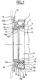
- the release stop comprises a rolling bearing 1 mounted on an operating element 2 by means of a self-centering member 3.
- the operating element 2 comprises a tubular portion 4 provided at its free end with a annular flange 5 protruding outwardly and having a radial surface 6 formed at the other end of the tubular portion 4.
- the bearing 1 is mounted in contact with the radial surface 6 of the operating element 2.
- the bearing 1 comprises a ring non-rotating inner 7, a rotating outer ring 8 made of pressed sheet, a row of rolling elements 9 held by a cage 10 and arranged between the inner ring 7 and outer ring 8.
- the ring 7 is provided with a radial portion 7a directed inwards which comes into contact with the radial surface 6 of the operating element 2, so that the operating element 2 can push the bearing 1 axially towards the diaphragm 15.
- the self-centering member 3 made for example of elastomer is disposed in the bore of the inner ring 7 and includes a plurality of teeth 11 radially flexible and extending towards the part tubular 5 of the operating element 2.
- the bearing 1 can therefore to self-center with respect to the operating element 2 by causing the bending of the teeth 11 of the self-centering member 3.
- a lip 12, resulting from the self-centering member 3, extends axially outward and rubs against the rotating outer ring 8.
- a sealing member 13 is also provided at the other end of the bearing 1.
- the sealing member 13 comprises a thin sheet metal element a fixing portion 13a surrounds a tubular portion 8a of the rotating ring 8 and a sealing portion 13b forms a narrow passage with the non-rotating ring 7.
- the sealing member 13 also comprises a flexible element in the form of a washer 13c disposed between the sheet metal element and the ring 8.
- the rotating outer ring 8 comprises a tubular portion 8a adjacent to the rolling track 8b provided for the row of elements 9, and in contact with the sealing member 13. axially opposite the operating element 2, the outer ring 8 comprises a rounded portion 8c of convexity facing away from rolling elements and an oblique portion 8d essentially radial extending inward extending the rounded portion 8c and slightly towards the rolling elements in the axial direction.
- the part 8c is in contact with an etching element 14, made of sheet metal Pressed.
- Attack element 14 in the form of a wave washer radially, comprises a convex portion 14a convex on the side of the outer ring 8 and applying at least in part against the portion rounded 8c of the outer ring 8, a convex portion 14b convex on the opposite side to the outer ring 8, disposed at the end of large diameter of the radial portion 14a, and forming a contact surface toroidal with the fingers 15 of a clutch diaphragm, and a small diameter end 14c substantially radial and diameter interior equal to that of the oblique portion 8d of the ring 8.
- the zone of small diameter 14c is distant from the oblique portion 8d.
- the part 8c can axially push the driver 14 towards the diaphragm 15.
- the convex surface of the curved portion 14b is in contact with the diaphragm 15 on the opposite side to the operating element 2 and bearing 1.
- An axial prestressing force applied to the small area diameter 14c of the driving element 14 and / or on the oblique portion 8d of the outer ring 8 may bring very slightly said area of small diameter 14c of said oblique portion 8d by axial deformation elastic of the driving element 14 and the outer ring 8.
- the device is completed by a connecting ring 16 forming means for fixing the driving element 14 on the outer ring 8 and means for bringing the driving element 14 into direct contact with the ring 8.
- the connecting ring 16 has a U-shaped section and comprises a tubular bottom 16a of axial length slightly greater than the sum of the thickness of the driver 14 and the outer ring 8, a radial edge 16c extending outwardly from the side rolling elements and a radial edge 16b extending towards the outside of the opposite side to the rolling elements.
- the end 14c of the element 14 and the end of the oblique portion 8d of the ring 8 are held between the edges 16b and 16c with a certain axial prestressing which creates a friction torque of preferably greater than the internal friction torque of the bearing.
- the driving element 14 and the outer ring 8 are thus solidary in rotation.
- the end 14c of the driving element 14 and the end of the oblique portion 8d of the outer ring 8 can be in contact with the tubular bottom 16a for a good centering of the ring 16.
- the connecting ring 16 is a single piece, of weak mass and economical manufacturing. Axial prestressing exerted by the connecting ring 16 on the outer ring 8 and the attacking element 14 allows a solidarity of these two parts, a simple assembly and easy to automate, a rigid link and negligible to play, and the use of a sheet metal driver.
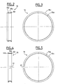
- FIGS 2 and 3 is illustrated the shaping of a ring link 16 circumferentially continuous.
- the connecting ring 16 is present in the form of a cup section L, the edge 16b not being not yet formed and extending axially.
- the edge 16b is then rolled or crimped to give it its final radial shape after assembly on the bearing.
- FIGS. 4 and 5 is shown a connecting ring 16 circumferentially discontinuous.
- the connecting ring 16 comprises a slot 17 formed on a short angular sector, which gives it a some radial elasticity for mounting.
- the link ring 16 is manufactured in its final form before mounting on the bearing.
- connecting ring 16 may have variants such as oblique edges 16b or 16c, a frustoconical bottom 16a, additional portions, etc.
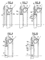
- FIGS. 6 to 8 the assembly with a ring of link 16 according to FIGS. 2 and 3.
- the connecting ring 16 is brought in the form of an L-section cup in the bore of the ring 8, confer FIG 6.
- the tubular bottom 16a is passed through the bore of the oblique portion 8d of the outer ring 8, until contact between the edge 16c and said oblique portion 8d. Simultaneously or no, axially brings the driving element 14 of the portion oblique 8d of the outer ring 8 to the contact, see FIG. tubular bottom 16a passes into the bore of the end 14c of the element of attack 14.
- the edge 16b of the connecting ring 16 is formed by plastic deformation of the end of the tubular bottom 16a, in particular by rolling or crimping, see FIG. 8, the driving element 14 and the outer ring 8 being axially preloaded against each other during this operation, so that it remains after the operation of crimping or rolling a residual axial preload now firmly the two parts in contact.
- FIGS. 9 and 10 the assembly with a ring of link 16 according to Figures 4 and 5. It is moved axially the driving element 14 of the oblique portion 8d of the outer ring 8 until contact, see figure 9.
- the ring of link 16 to decrease its outside diameter by decreasing the width of the slot 17.
- the connecting ring 16 is passed through the bore of the portion oblique 8d of the outer ring 8 and in the bore of the end 14c of the driving element 14. Then release the link ring 16 which substantially resumes its diameter in the free state with contact between the edge 16c and said oblique portion 8d and between the edge 16b and the end 14c of the driving element 14.
- the axle is clamped axially oblique portion 8d of the outer ring 8 and the end 14c of the driving element 14 to facilitate the loosening of the ring of connection 16 and the relative displacement of the edges 16b and 16c with respect to the oblique portion 8d of the outer ring 8 and the end 14c of the driving element 14.
- the slot 17 substantially resumes its width before assembly.
- the distance between the edges 16b and 16c is advantageously slightly less than the distance between the face of the oblique portion 8d of the outer ring 8 on the side of the rolling elements 9 and the face of the bore of the end 14c of the driving element 14 on the opposite side to the rolling elements 9 in order to maintain after installation a slight residual axial prestressing of the oblique portion 8d of the outer ring 8 and the driving member 14 sufficient to maintain them in rotation in conditions normal.
- the driving element 14 can be manufactured in a very economic from a steel strip, by cutting, stamping and folding, said etching element once formed undergoing treatment thermal hardening limiting its wear due to contact with the fingers 15 of the clutch diaphragm.
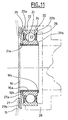
- FIG. 11 an embodiment of the invention adapted to a standard conventional bearing rings massive.
- the bearing 20 comprises a rotating inner ring 21, a non-rotating outer ring 22, a row of rolling elements 23, here balls, arranged between raceways formed on the inner and outer rings 22 and held by a cage 24, and sealing elements 25 and 26 mounted on both sides of the rolling elements 23 and closing the space between the inner rings 21 and outer 22.
- the sealing elements 25 and 26 are identical.
- the inner rings 21 and outer 22 are massive type and have a raceway forming a concavity for ratio, respectively, to the outer surface and the inner surface inner rings 21 and outer 22.
- the outer ring 22 comprises radial frontal surfaces 22a and 22b coplanar with the corresponding radial front surfaces 21a and 21b of the ring inside 21.
- Attack 27 in the form of a wave washer radially, comprises a convex portion 27a of small diameter convex side of the inner ring 21 and applying at least in against the radial front surface 21a of the inner ring 21, and a convex portion 27b of large convex diameter on the opposite side to the inner ring 21 and forming a toroidal contact surface with the fingers 15 of a clutch diaphragm.
- a connecting ring 16 is mounted in the bore of the ring 21 and in the bore of the driving element 27.
- the edge 16c of the connecting ring 16 is in contact with the radial front surface 21b of the inner ring 21 and the edge 16b is in contact with the element of attack 27 near its bore on the side of the diaphragm 15.
- the bearing 20 is mounted by its outer ring 22 in a housing 28 shown in phantom.
- the element of attack reported allows, in a very economical way, to equip a sheet stop existing in order to use it with a diaphragm diameter for which it had not been initially planned, thus avoiding the development and manufacture of a new customized bearing.
- the reported attack element also makes it possible to transform extremely quickly a conventional standard bearing with rings Massive, mass produced, in a clutch release bearing specific and adapted to a particular diameter of diaphragm.
- the reported driving element is economical to manufacture, easy to set up by a simple axial movement and does not modify the game initial internal bearing. Indeed, the attacking element and the ring of binding cooperate with the rotating ring without exerting any constraint risk of deforming said ring in the radial direction and therefore of change the internal clearance of the bearing.
Landscapes
- Engineering & Computer Science (AREA)
- General Engineering & Computer Science (AREA)
- Mechanical Engineering (AREA)
- Mechanical Operated Clutches (AREA)
Description
- la figure 1 est une vue de côté en coupe axiale d'une butée d'embrayage selon un aspect de l'invention;
- la figure 2 est une vue de côté en coupe axiale d'un premier mode de réalisation d'anneau de liaison de la figure 1;
- la figure 3 est une vue avant en élévation de l'anneau de liaison de la figure 2;
- la figure 4 est une vue de côté en coupe axiale d'un deuxième mode de réalisation d'anneau de liaison de la figure 1;
- la figure 5 est une vue avant en élévation de l'anneau de liaison de la figure 4;
- les figures 6 à 8 sont des vues partielles en coupe axiale du roulement équipé de l'anneau de liaison des figures 2 et 3 en cours de montage;
- les figures 9 et 10 sont des vues partielles en coupe axiale du roulement équipé de l'anneau de liaison des figures 4 et 5 en cours de montage; et
- la figure 11 est une vue de côté en coupe axiale d'une butée d'embrayage selon un autre aspect de l'invention.
Claims (16)
- Dispositif de butée de débrayage, du type comprenant un palier à roulement (1) muni d'une bague non tournante (7) et d'une bague tournante (8), ledit dispositif étant capable d'agir sur un diaphragme (15) de mécanisme d'embrayage, et comprenant un élément d'attaque (14) solidaire et en contact avec la bague tournante et prévu pour entrer en contact avec le diaphragme, la surface de l'élément d'attaque prévue pour contact avec le diaphragme étant disposée du côté opposé au palier à roulement caractérisé par le fait que l'élément d'attaque est solidarisé avec la bague tournante au moyen d'un anneau de liaison (16) comprenant une portion cylindrique (16a) traversant un alésage de la bague tournante et un alésage de l'élément d'attaque, et deux bords (16b, 16c) sensiblement radiaux dirigés vers l'extérieur en contact axial l'un avec la bague tournante et l'autre avec l'élément d'attaque pour maintenir ensemble la bague tournante et l'élément d'attaque.
- Dispositif selon la revendication 1, caractérisé par le fait que l'élément d'attaque est réalisé en tôle emboutie.
- Dispositif selon la revendication 1 ou 2, caractérisé par le fait que l'élément d'attaque présente une forme de rondelle ondulée radialement.
- Dispositif selon l'une quelconque des revendications précédentes, caractérisé par le fait que l'anneau de liaison est circonférentiellement continu.
- Dispositif selon l'une quelconque des revendications 1 à 3, caractérisé par le fait que l'anneau de liaison est monobloc et circonférentiellement discontinu.
- Dispositif selon l'une quelconque des revendications précédentes, caractérisé par le fait que l'anneau de liaison précontraint axialement l'élément d'attaque et la bague tournante.
- Dispositif selon l'une quelconque des revendications précédentes, caractérisé par le fait que la bague tournante (8) est en tôle emboutie.
- Dispositif selon l'une quelconque des revendications précédentes, caractérisé par le fait que la bague tournante est extérieure.
- Dispositif selon l'une quelconque des revendications 1 à 7, caractérisé par le fait que la bague tournante est intérieure.
- Embrayage comprenant un dispositif selon l'une quelconque des revendications précédentes et un diaphragme de diamètre de contact avec l'élément d'attaque supérieur au diamètre extérieur de la bague extérieure du roulement.
- Procédé de montage d'une butée de débrayage comprenant un palier à roulement (1) muni d'une bague non tournante (7) et d'une bague tournante (8), dans lequel on fixe avec précontrainte sur la bague tournante un élément d'attaque prévu pour entrer en contact avec un diaphragme, au moyen d'un anneau de liaison dont une portion cylindrique traverse un alésage de la bague tournante et un alésage de l'élément d'attaque, et deux bords sensiblement radiaux sont dirigés vers l'extérieur en contact axial l'un avec la bague tournante et l'autre avec l'élément d'attaque, la surface de l'élément d'attaque prévue pour contact avec le diaphragme étant disposée du côté opposé au palier à roulement.
- Procédé selon la revendication 11, dans lequel la fixation est assurée par l'insertion d'une coupelle à section en L dans l'alésage de la bague tournante et l'alésage de l'élément d'attaque et la formation du deuxième rebord à partir de l'extrémité de la portion cylindrique.
- Procédé selon la revendication 12, dans lequel la formation du deuxième rebord est réalisée par sertissage.
- Procédé selon la revendication 12, dans lequel la formation du deuxième rebord est réalisée par roulage.
- Procédé selon la revendication 11, dans lequel la fixation est assurée par le rétreint radial et l'insertion de l'anneau de liaison dans l'alésage de la bague tournante et l'alésage de l'élément d'attaque, ledit anneau de liaison étant fendu, puis par l'expansion radiale de l'anneau de liaison.
- Procédé selon l'une quelconque des revendications 11-15, dans lequel l'élément d'attaque (14) et la bague tournante (8) sont précontraints axialement l'un contre l'autre.
Applications Claiming Priority (2)
| Application Number | Priority Date | Filing Date | Title |
|---|---|---|---|
| FR0214259 | 2002-11-14 | ||
| FR0214259A FR2847318B1 (fr) | 2002-11-14 | 2002-11-14 | Butee de debrayage avec element d'attaque rapporte et procede de fabrication |
Publications (2)
| Publication Number | Publication Date |
|---|---|
| EP1420184A1 EP1420184A1 (fr) | 2004-05-19 |
| EP1420184B1 true EP1420184B1 (fr) | 2005-03-16 |
Family
ID=32116615
Family Applications (1)
| Application Number | Title | Priority Date | Filing Date |
|---|---|---|---|
| EP03292770A Expired - Lifetime EP1420184B1 (fr) | 2002-11-14 | 2003-11-05 | Butée de débrayage avec élément d'attaque rapporté et procédé de fabrication |
Country Status (3)
| Country | Link |
|---|---|
| EP (1) | EP1420184B1 (fr) |
| DE (1) | DE60300390T2 (fr) |
| FR (1) | FR2847318B1 (fr) |
Cited By (2)
| Publication number | Priority date | Publication date | Assignee | Title |
|---|---|---|---|---|
| CN101493111B (zh) * | 2008-10-22 | 2010-08-11 | 陈炳顺 | 特种碟形弹簧垫圈及离合器分离轴承组件 |
| CN104653629A (zh) * | 2013-11-19 | 2015-05-27 | Skf公司 | 用于制造轴承外圈和离合器分离轴承装置的方法 |
Families Citing this family (4)
| Publication number | Priority date | Publication date | Assignee | Title |
|---|---|---|---|---|
| DE102004034439A1 (de) * | 2004-07-16 | 2006-02-02 | Ina-Schaeffler Kg | Kupplungsausrücklager |
| FR2904072B1 (fr) * | 2006-07-24 | 2009-05-08 | Snr Roulements Sa | Rondelle d'autocentrage pour butee d'embrayage de geometrie limitant la plastification des dents |
| FR2904073B1 (fr) * | 2006-07-24 | 2008-12-26 | Snr Roulements Sa | Rondelle d'autocentrage pour butee d'embrayage de geometrie limitant la plastification des ondes |
| FR3034830B1 (fr) * | 2015-04-07 | 2018-10-12 | Aktiebolaget Skf | Butee d'embrayage-debrayage et vehicule automobile equipe d'une telle butee |
Family Cites Families (3)
| Publication number | Priority date | Publication date | Assignee | Title |
|---|---|---|---|---|
| FR2539832A1 (fr) * | 1983-01-24 | 1984-07-27 | Valeo | Butee de debrayage de type tire en deux parties, notamment pour vehicule automobile |
| DE3706031A1 (de) * | 1987-02-25 | 1988-09-08 | Schaeffler Waelzlager Kg | Kraftfahrzeug-reibungskupplung |
| FR2795790B1 (fr) * | 1999-07-02 | 2001-10-26 | Valeo | Butee de debrayage du type tire pour un embrayage a diaphragme et son procede de montage |
-
2002
- 2002-11-14 FR FR0214259A patent/FR2847318B1/fr not_active Expired - Fee Related
-
2003
- 2003-11-05 DE DE60300390T patent/DE60300390T2/de not_active Expired - Lifetime
- 2003-11-05 EP EP03292770A patent/EP1420184B1/fr not_active Expired - Lifetime
Cited By (3)
| Publication number | Priority date | Publication date | Assignee | Title |
|---|---|---|---|---|
| CN101493111B (zh) * | 2008-10-22 | 2010-08-11 | 陈炳顺 | 特种碟形弹簧垫圈及离合器分离轴承组件 |
| CN104653629A (zh) * | 2013-11-19 | 2015-05-27 | Skf公司 | 用于制造轴承外圈和离合器分离轴承装置的方法 |
| CN104653629B (zh) * | 2013-11-19 | 2018-09-18 | Skf公司 | 用于制造轴承外圈和离合器分离轴承装置的方法 |
Also Published As
| Publication number | Publication date |
|---|---|
| DE60300390T2 (de) | 2006-02-09 |
| FR2847318B1 (fr) | 2005-12-16 |
| DE60300390D1 (de) | 2005-04-21 |
| FR2847318A1 (fr) | 2004-05-21 |
| EP1420184A1 (fr) | 2004-05-19 |
Similar Documents
| Publication | Publication Date | Title |
|---|---|---|
| EP0941414B1 (fr) | Palier a roulement de colonne de direction pour vehicules automobiles | |
| EP1489327B1 (fr) | Butée de débrayage et procédé de montage | |
| EP1489325B1 (fr) | Butée de débrayage | |
| FR2737173A1 (fr) | Colonne de direction reglable en profondeur, avec dispositif de guidage | |
| FR2860847A1 (fr) | Dispositif de butee de debrayage | |
| EP1080317B1 (fr) | Butee de debrayage a auto-alignement par manchon | |
| FR2765297A1 (fr) | Appareil d'accouplement hydrocinetique a embrayage de verrouillage, pour vehicule automobile | |
| EP1420184B1 (fr) | Butée de débrayage avec élément d'attaque rapporté et procédé de fabrication | |
| EP2142817B1 (fr) | Compresseur de climatisation | |
| EP0892188B1 (fr) | Butée de débrayage avec surface d'attaque rapportée | |
| FR2777328A1 (fr) | Dispositif de manoeuvre pour un embrayage | |
| EP1367281B1 (fr) | Butée de débrayage avec élément d'attaque rapporté | |
| EP1813826B1 (fr) | Dispositif de liaison amovible comportant une agrafe de verrouillage | |
| FR2760057A1 (fr) | Dispositif de roue libre a flasque de retenue et procede de mise en place du flasque | |
| JP2005121211A (ja) | 連続転位を伴う保持カラーの製造方法 | |
| EP1409883B1 (fr) | Palier a roulement de colonne de direction pour vehicule automobile | |
| FR2782758A1 (fr) | Palier a roulement | |
| FR2683284A1 (fr) | Butee de debrayage hydraulique, pour montage de butee de debrayage et procede d'assemblage d'un tel montage de butee de debrayage. | |
| EP0239457B1 (fr) | Volant amortisseur pour transmission, notamment pour véhicule automobile | |
| WO1996007837A1 (fr) | Volant amortisseur, notamment pour vehicule automobile | |
| FR2816017A1 (fr) | Cage de maitien d'elements de coincement pour dispositif de roue libre et dispositif de roue libre | |
| EP0736146B1 (fr) | Butee de debrayage | |
| WO1997036119A1 (fr) | Montage de butee de debrayage | |
| FR2876170A1 (fr) | Butee de debrayage autocentreuse et procede de montage | |
| FR2747441A1 (fr) | Montage de butee de debrayage |
Legal Events
| Date | Code | Title | Description |
|---|---|---|---|
| PUAI | Public reference made under article 153(3) epc to a published international application that has entered the european phase |
Free format text: ORIGINAL CODE: 0009012 |
|
| AK | Designated contracting states |
Kind code of ref document: A1 Designated state(s): AT BE BG CH CY CZ DE DK EE ES FI FR GB GR HU IE IT LI LU MC NL PT RO SE SI SK TR |
|
| AX | Request for extension of the european patent |
Extension state: AL LT LV MK |
|
| 17P | Request for examination filed |
Effective date: 20040428 |
|
| 17Q | First examination report despatched |
Effective date: 20040622 |
|
| GRAP | Despatch of communication of intention to grant a patent |
Free format text: ORIGINAL CODE: EPIDOSNIGR1 |
|
| GRAS | Grant fee paid |
Free format text: ORIGINAL CODE: EPIDOSNIGR3 |
|
| GRAA | (expected) grant |
Free format text: ORIGINAL CODE: 0009210 |
|
| AKX | Designation fees paid |
Designated state(s): DE FR GB IT |
|
| AK | Designated contracting states |
Kind code of ref document: B1 Designated state(s): DE FR GB IT |
|
| PG25 | Lapsed in a contracting state [announced via postgrant information from national office to epo] |
Ref country code: GB Free format text: LAPSE BECAUSE OF FAILURE TO SUBMIT A TRANSLATION OF THE DESCRIPTION OR TO PAY THE FEE WITHIN THE PRESCRIBED TIME-LIMIT Effective date: 20050316 |
|
| REG | Reference to a national code |
Ref country code: GB Ref legal event code: FG4D Free format text: NOT ENGLISH |
|
| REG | Reference to a national code |
Ref country code: IE Ref legal event code: FG4D Free format text: FRENCH |
|
| REF | Corresponds to: |
Ref document number: 60300390 Country of ref document: DE Date of ref document: 20050421 Kind code of ref document: P |
|
| GBV | Gb: ep patent (uk) treated as always having been void in accordance with gb section 77(7)/1977 [no translation filed] |
Effective date: 20050316 |
|
| PLBE | No opposition filed within time limit |
Free format text: ORIGINAL CODE: 0009261 |
|
| STAA | Information on the status of an ep patent application or granted ep patent |
Free format text: STATUS: NO OPPOSITION FILED WITHIN TIME LIMIT |
|
| 26N | No opposition filed |
Effective date: 20051219 |
|
| PGFP | Annual fee paid to national office [announced via postgrant information from national office to epo] |
Ref country code: FR Payment date: 20131129 Year of fee payment: 11 Ref country code: IT Payment date: 20131127 Year of fee payment: 11 |
|
| PGFP | Annual fee paid to national office [announced via postgrant information from national office to epo] |
Ref country code: DE Payment date: 20140131 Year of fee payment: 11 |
|
| REG | Reference to a national code |
Ref country code: DE Ref legal event code: R119 Ref document number: 60300390 Country of ref document: DE |
|
| REG | Reference to a national code |
Ref country code: FR Ref legal event code: ST Effective date: 20150731 |
|
| PG25 | Lapsed in a contracting state [announced via postgrant information from national office to epo] |
Ref country code: DE Free format text: LAPSE BECAUSE OF NON-PAYMENT OF DUE FEES Effective date: 20150602 |
|
| PG25 | Lapsed in a contracting state [announced via postgrant information from national office to epo] |
Ref country code: FR Free format text: LAPSE BECAUSE OF NON-PAYMENT OF DUE FEES Effective date: 20141201 |
|
| PG25 | Lapsed in a contracting state [announced via postgrant information from national office to epo] |
Ref country code: IT Free format text: LAPSE BECAUSE OF NON-PAYMENT OF DUE FEES Effective date: 20141105 |