EP1419914A1 - Power window device fitted on the lock of the motor vehicle door - Google Patents
Power window device fitted on the lock of the motor vehicle door Download PDFInfo
- Publication number
- EP1419914A1 EP1419914A1 EP03380228A EP03380228A EP1419914A1 EP 1419914 A1 EP1419914 A1 EP 1419914A1 EP 03380228 A EP03380228 A EP 03380228A EP 03380228 A EP03380228 A EP 03380228A EP 1419914 A1 EP1419914 A1 EP 1419914A1
- Authority
- EP
- European Patent Office
- Prior art keywords
- motor vehicle
- lock
- power window
- vehicle door
- window device
- Prior art date
- Legal status (The legal status is an assumption and is not a legal conclusion. Google has not performed a legal analysis and makes no representation as to the accuracy of the status listed.)
- Granted
Links
Images
Classifications
-
- B—PERFORMING OPERATIONS; TRANSPORTING
- B60—VEHICLES IN GENERAL
- B60J—WINDOWS, WINDSCREENS, NON-FIXED ROOFS, DOORS, OR SIMILAR DEVICES FOR VEHICLES; REMOVABLE EXTERNAL PROTECTIVE COVERINGS SPECIALLY ADAPTED FOR VEHICLES
- B60J5/00—Doors
- B60J5/04—Doors arranged at the vehicle sides
- B60J5/0412—Lower door structure
- B60J5/0416—Assembly panels to be installed in doors as a module with components, e.g. lock or window lifter, attached thereto
-
- E—FIXED CONSTRUCTIONS
- E05—LOCKS; KEYS; WINDOW OR DOOR FITTINGS; SAFES
- E05F—DEVICES FOR MOVING WINGS INTO OPEN OR CLOSED POSITION; CHECKS FOR WINGS; WING FITTINGS NOT OTHERWISE PROVIDED FOR, CONCERNED WITH THE FUNCTIONING OF THE WING
- E05F15/00—Power-operated mechanisms for wings
- E05F15/60—Power-operated mechanisms for wings using electrical actuators
- E05F15/603—Power-operated mechanisms for wings using electrical actuators using rotary electromotors
- E05F15/665—Power-operated mechanisms for wings using electrical actuators using rotary electromotors for vertically-sliding wings
-
- B—PERFORMING OPERATIONS; TRANSPORTING
- B60—VEHICLES IN GENERAL
- B60J—WINDOWS, WINDSCREENS, NON-FIXED ROOFS, DOORS, OR SIMILAR DEVICES FOR VEHICLES; REMOVABLE EXTERNAL PROTECTIVE COVERINGS SPECIALLY ADAPTED FOR VEHICLES
- B60J1/00—Windows; Windscreens; Accessories therefor
- B60J1/08—Windows; Windscreens; Accessories therefor arranged at vehicle sides
- B60J1/12—Windows; Windscreens; Accessories therefor arranged at vehicle sides adjustable
- B60J1/16—Windows; Windscreens; Accessories therefor arranged at vehicle sides adjustable slidable
- B60J1/17—Windows; Windscreens; Accessories therefor arranged at vehicle sides adjustable slidable vertically
-
- B—PERFORMING OPERATIONS; TRANSPORTING
- B60—VEHICLES IN GENERAL
- B60J—WINDOWS, WINDSCREENS, NON-FIXED ROOFS, DOORS, OR SIMILAR DEVICES FOR VEHICLES; REMOVABLE EXTERNAL PROTECTIVE COVERINGS SPECIALLY ADAPTED FOR VEHICLES
- B60J5/00—Doors
- B60J5/04—Doors arranged at the vehicle sides
-
- E—FIXED CONSTRUCTIONS
- E05—LOCKS; KEYS; WINDOW OR DOOR FITTINGS; SAFES
- E05B—LOCKS; ACCESSORIES THEREFOR; HANDCUFFS
- E05B81/00—Power-actuated vehicle locks
- E05B81/02—Power-actuated vehicle locks characterised by the type of actuators used
- E05B81/04—Electrical
- E05B81/06—Electrical using rotary motors
-
- E—FIXED CONSTRUCTIONS
- E05—LOCKS; KEYS; WINDOW OR DOOR FITTINGS; SAFES
- E05F—DEVICES FOR MOVING WINGS INTO OPEN OR CLOSED POSITION; CHECKS FOR WINGS; WING FITTINGS NOT OTHERWISE PROVIDED FOR, CONCERNED WITH THE FUNCTIONING OF THE WING
- E05F15/00—Power-operated mechanisms for wings
- E05F15/60—Power-operated mechanisms for wings using electrical actuators
- E05F15/603—Power-operated mechanisms for wings using electrical actuators using rotary electromotors
- E05F15/665—Power-operated mechanisms for wings using electrical actuators using rotary electromotors for vertically-sliding wings
- E05F15/689—Power-operated mechanisms for wings using electrical actuators using rotary electromotors for vertically-sliding wings specially adapted for vehicle windows
-
- E—FIXED CONSTRUCTIONS
- E05—LOCKS; KEYS; WINDOW OR DOOR FITTINGS; SAFES
- E05B—LOCKS; ACCESSORIES THEREFOR; HANDCUFFS
- E05B81/00—Power-actuated vehicle locks
- E05B81/12—Power-actuated vehicle locks characterised by the function or purpose of the powered actuators
- E05B81/13—Power-actuated vehicle locks characterised by the function or purpose of the powered actuators a single actuator for driving a lock and additional vehicle components, e.g. window wipers or window lifters
-
- E—FIXED CONSTRUCTIONS
- E05—LOCKS; KEYS; WINDOW OR DOOR FITTINGS; SAFES
- E05F—DEVICES FOR MOVING WINGS INTO OPEN OR CLOSED POSITION; CHECKS FOR WINGS; WING FITTINGS NOT OTHERWISE PROVIDED FOR, CONCERNED WITH THE FUNCTIONING OF THE WING
- E05F11/00—Man-operated mechanisms for operating wings, including those which also operate the fastening
- E05F11/38—Man-operated mechanisms for operating wings, including those which also operate the fastening for sliding windows, e.g. vehicle windows, to be opened or closed by vertical movement
- E05F11/48—Man-operated mechanisms for operating wings, including those which also operate the fastening for sliding windows, e.g. vehicle windows, to be opened or closed by vertical movement operated by cords or chains or other flexible elongated pulling elements, e.g. tapes
- E05F11/481—Man-operated mechanisms for operating wings, including those which also operate the fastening for sliding windows, e.g. vehicle windows, to be opened or closed by vertical movement operated by cords or chains or other flexible elongated pulling elements, e.g. tapes for vehicle windows
- E05F11/483—Man-operated mechanisms for operating wings, including those which also operate the fastening for sliding windows, e.g. vehicle windows, to be opened or closed by vertical movement operated by cords or chains or other flexible elongated pulling elements, e.g. tapes for vehicle windows by cables
-
- E—FIXED CONSTRUCTIONS
- E05—LOCKS; KEYS; WINDOW OR DOOR FITTINGS; SAFES
- E05Y—INDEXING SCHEME ASSOCIATED WITH SUBCLASSES E05D AND E05F, RELATING TO CONSTRUCTION ELEMENTS, ELECTRIC CONTROL, POWER SUPPLY, POWER SIGNAL OR TRANSMISSION, USER INTERFACES, MOUNTING OR COUPLING, DETAILS, ACCESSORIES, AUXILIARY OPERATIONS NOT OTHERWISE PROVIDED FOR, APPLICATION THEREOF
- E05Y2201/00—Constructional elements; Accessories therefor
- E05Y2201/60—Suspension or transmission members; Accessories therefor
- E05Y2201/622—Suspension or transmission members elements
- E05Y2201/64—Carriers
- E05Y2201/642—Trackless carriers
-
- E—FIXED CONSTRUCTIONS
- E05—LOCKS; KEYS; WINDOW OR DOOR FITTINGS; SAFES
- E05Y—INDEXING SCHEME ASSOCIATED WITH SUBCLASSES E05D AND E05F, RELATING TO CONSTRUCTION ELEMENTS, ELECTRIC CONTROL, POWER SUPPLY, POWER SIGNAL OR TRANSMISSION, USER INTERFACES, MOUNTING OR COUPLING, DETAILS, ACCESSORIES, AUXILIARY OPERATIONS NOT OTHERWISE PROVIDED FOR, APPLICATION THEREOF
- E05Y2900/00—Application of doors, windows, wings or fittings thereof
- E05Y2900/50—Application of doors, windows, wings or fittings thereof for vehicles
- E05Y2900/53—Type of wing
- E05Y2900/55—Windows
Definitions
- the present patent application relates, as stated in its title, to an "IMPROVED POWER WINDOW DEVICE FITTED ON THE LOCK OF THE MOTOR VEHICLE DOOR" which novel manufacturing, conformation and design features fulfil the purpose to which it has been specifically conceived, with a maximum safety and effectiveness.
- the invention is applied to a specific type of power window devices in motor vehicles adapted to be mounted directly on the gearmotor assembly in the lock of the door.
- a power window device of this type is described in the Spanish Patent Application P200202217 filed in the name of the same applicant.
- Said power window device essentially comprises a first guiding and sliding assembly fitted into the doorframe of the motor vehicle door and a second guiding and sliding assembly provided in the rail of the power window device, said assemblies being provided with sliding members fixed to the window pane.
- driving means for said guiding and sliding assemblies and the whole assembly is mounted, as stated before, in the motor vehicle lock with the rail secured thereto.
- variables of the design in said power window assembly were set forth and they were depending on various parameters as the distance between points of contact of the sliding member in the rail; the distance from the upper edge of the window pane to the fastening edge of the sliding member; the distance from an end of the rail to the points of contact; the height from the lower portion of the motor vehicle door to the belt line; the window height, etc.
- the present invention provides a new improved power window device fitted on the lock of the motor vehicle door having an extremely simple construction and a very effective operation as it achieves a high dynamic stability.
- the power window device of the invention essentially comprises guiding and sliding means and driving means for the motor vehicle window pane which, as it has been previously stated, are mounted in the lock of the motor vehicle.
- Said driving means of the window pane include an electric motor and a gearmotor assembly acting on a driving cable.
- said guiding and sliding means for the window pane comprises respective rails positively mounted on opposed edges of the inner panel of the motor vehicle door. This configuration allows to remove the rail in the conventional power window devices thus simplifying the assembly.
- the power window device of the invention only includes two pulleys for a single driving cable.
- This feature involves a further simplification of the power window device of the present invention with regard to the double-rail power window devices of the prior art which use four pulleys.
- the use of two pulleys is due to the fact that only a single driving cable is present.
- said two pulleys are positively fixed to the inner panel of the door through their own shaft.
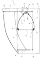
- the door of a motor vehicle is shown indicated at (1) which is provided with an improved power window device (2) mounted in the lock (3) thereof according to the invention.
- the power window device (2) comprises guiding and sliding means for the window pane (4) of the door (1) and driving means (5) for said window pane (4) which are mounted in said lock (3).
- These driving means (5) for the window pane (4) include an electric motor and a gearmotor assembly (not shown) acting on a driving cable (6).
- Said guiding and sliding means for the window pane (4) comprises respective U-shaped cross-section rails (7, 8) through which said window pane (4) is allowed to slide.
- These rails (7, 8) are positively mounted in opposed edges of the inner panel (9) of the motor vehicle door (1), that is to say, in the pillar (A) and in the pillar (B) of the door, respectively.
- the driving cable (6) is a single cable and it is only wound in its travel around two pulleys (10, 11) which are positively attached to the inner panel (9) of the door (1) through their own shaft. In said panel (9) of the door (1), the corresponding end of travel inner stops (12, 13) are fixed.
- the driving cable (6) also includes a support (14) secured to the window pane (4) so that the movement of said driving cable (6) in either direction causes the rising or lowering action of the window pane (4) by actuating said driving means (5) mounted in the lock (3).
- the upper and lower sections of the driving cable (6) are placed within respective sheaths (15, 16) thus ensuring tightening thereof by means of springs (17, 18).
- the assembly of the power window device (2) may be greatly facilitated by releasing the cable (6) by any appropriate means which allows prestressing said springs (17, 18) during assembly. Once the assembly is assembled, the operator removes said means acting on the said springs so that they will be expanded back tightening the cable (6).
Landscapes
- Engineering & Computer Science (AREA)
- Mechanical Engineering (AREA)
- Power-Operated Mechanisms For Wings (AREA)
- Window Of Vehicle (AREA)
Abstract
Description
- The present patent application relates, as stated in its title, to an "IMPROVED POWER WINDOW DEVICE FITTED ON THE LOCK OF THE MOTOR VEHICLE DOOR" which novel manufacturing, conformation and design features fulfil the purpose to which it has been specifically conceived, with a maximum safety and effectiveness.
- The invention is applied to a specific type of power window devices in motor vehicles adapted to be mounted directly on the gearmotor assembly in the lock of the door. A power window device of this type is described in the Spanish Patent Application P200202217 filed in the name of the same applicant. Said power window device essentially comprises a first guiding and sliding assembly fitted into the doorframe of the motor vehicle door and a second guiding and sliding assembly provided in the rail of the power window device, said assemblies being provided with sliding members fixed to the window pane. There are also included driving means for said guiding and sliding assemblies and the whole assembly is mounted, as stated before, in the motor vehicle lock with the rail secured thereto.
- In this patent the variables of the design in said power window assembly were set forth and they were depending on various parameters as the distance between points of contact of the sliding member in the rail; the distance from the upper edge of the window pane to the fastening edge of the sliding member; the distance from an end of the rail to the points of contact; the height from the lower portion of the motor vehicle door to the belt line; the window height, etc.
- By determining the relationship between the previous variables it was allowed to overcome the drawback of the conventional power window devices secured to the motor vehicle lock arisen from instability of the assembly in use. This instability was produced since fastening of the window pane in the sliding member and guiding thereof had certain looseness which negatively influenced on the system operation, which were amplified by the action of the large cantilever of the window pane (the power window device is mounted in the lock, in a side end of the door).
- Once said variables were defined in the main patent, it has been found that the appropriate and more advantageous structural configuration is the one herein described according to the present invention.
- The present invention provides a new improved power window device fitted on the lock of the motor vehicle door having an extremely simple construction and a very effective operation as it achieves a high dynamic stability.
- The power window device of the invention essentially comprises guiding and sliding means and driving means for the motor vehicle window pane which, as it has been previously stated, are mounted in the lock of the motor vehicle. Said driving means of the window pane include an electric motor and a gearmotor assembly acting on a driving cable.
- The main feature of the invention is that said guiding and sliding means for the window pane comprises respective rails positively mounted on opposed edges of the inner panel of the motor vehicle door. This configuration allows to remove the rail in the conventional power window devices thus simplifying the assembly.
- Preferably, the power window device of the invention only includes two pulleys for a single driving cable. This feature involves a further simplification of the power window device of the present invention with regard to the double-rail power window devices of the prior art which use four pulleys. The use of two pulleys is due to the fact that only a single driving cable is present. In addition, according to the invention, said two pulleys are positively fixed to the inner panel of the door through their own shaft.
- Many advantages are achieved and they are associated to a large extent with a drastic cost reduction. The extreme mechanical simplification of the assembly by reducing the number of parts in the power window device allows to reduce the final cost thereof. Further, with said smaller number of parts, it is also possible to reduce friction produced in operation and consequently noise is also reduced. On the other hand, the assembly of the power window device that is herein described is considerably simpler and quicker than that of the known power window devices.
- These advantages and features of the power window device of the present invention which have been previously set out will be clearer from the detailed description of a preferred embodiment thereof which will be given hereinafter by way of a non limitative example, with reference to the drawing that is herein enclosed, wherein a side elevational view of a motor vehicle door provided with a preferred embodiment of a power window device according to the invention is shown.
- A detailed list of the various parts cited in the present patent application is given below::
- (1) motor vehicle door;
- (2) power window device;
- (3) lock;
- (4) window pane;
- (5) window pane driving means;
- (6) driving cable;
- (7) rail;
- (8) rail;
- (9) inner panel of the door;
- (10) pulley;
- (11) pulley;
- (12) end of travel lower stop;
- (13) end of travel lower stop;
- (14) window pane support;
- (15) driving cable sheath;
- (16) driving cable sheath;
- (17) spring;
- (18) spring; (A, B) door pillars.
-
- In the figure which is herein enclosed, the door of a motor vehicle is shown indicated at (1) which is provided with an improved power window device (2) mounted in the lock (3) thereof according to the invention.
- The power window device (2) comprises guiding and sliding means for the window pane (4) of the door (1) and driving means (5) for said window pane (4) which are mounted in said lock (3). These driving means (5) for the window pane (4) include an electric motor and a gearmotor assembly (not shown) acting on a driving cable (6).
- Said guiding and sliding means for the window pane (4) comprises respective U-shaped cross-section rails (7, 8) through which said window pane (4) is allowed to slide. These rails (7, 8) are positively mounted in opposed edges of the inner panel (9) of the motor vehicle door (1), that is to say, in the pillar (A) and in the pillar (B) of the door, respectively. The driving cable (6) is a single cable and it is only wound in its travel around two pulleys (10, 11) which are positively attached to the inner panel (9) of the door (1) through their own shaft. In said panel (9) of the door (1), the corresponding end of travel inner stops (12, 13) are fixed.
- As it can be seen, the driving cable (6) also includes a support (14) secured to the window pane (4) so that the movement of said driving cable (6) in either direction causes the rising or lowering action of the window pane (4) by actuating said driving means (5) mounted in the lock (3).
- The upper and lower sections of the driving cable (6) are placed within respective sheaths (15, 16) thus ensuring tightening thereof by means of springs (17, 18). The assembly of the power window device (2) may be greatly facilitated by releasing the cable (6) by any appropriate means which allows prestressing said springs (17, 18) during assembly. Once the assembly is assembled, the operator removes said means acting on the said springs so that they will be expanded back tightening the cable (6).
- Once having been sufficiently described what the improved power window device fitted on the lock of the motor vehicle door of the present patent application consists in accordance to the enclosed drawings, it is understood that any detail modification can be introduced as appropriate, provided that variations may alter the essence of the invention as summarised in the appended claims.
Claims (3)
- "IMPROVED POWER WINDOW DEVICE FITTED ON THE LOCK OF THE MOTOR VEHICLE DOOR" said power window device (2) comprising guiding and sliding means for the motor vehicle window pane (4) and driving means (5) for said window pane mounted in the motor vehicle lock (3) which include an electric motor and a gearmotor assembly acting on a driving cable (6), characterized in that said guiding and sliding means for the window pane comprise respective rails (7, 8) positively mounted on opposed edges (A, B) of the inner panel (9) of the motor vehicle door (1).
- "IMPROVED POWER WINDOW DEVICE FITTED ON THE LOCK OF THE MOTOR VEHICLE DOOR" according to claim 1, characterized in that it is provided only with two pulleys (10, 11) for a single driving cable (6).
- "IMPROVED POWER WINDOW DEVICE FITTED ON THE LOCK OF THE MOTOR VEHICLE DOOR" according to claim 2, characterized in that said pulleys (10, 11) are positively mounted fixed to the inner panel (9) of the door (1) through their own shaft.
Applications Claiming Priority (2)
| Application Number | Priority Date | Filing Date | Title |
|---|---|---|---|
| ES200202611 | 2002-11-14 | ||
| ES200202611A ES2232255B1 (en) | 2002-11-14 | 2002-11-14 | PERFECTED ELEVALUNAS MOUNTED ON THE DOOR LOCK OF A MOTOR VEHICLE. |
Publications (2)
| Publication Number | Publication Date |
|---|---|
| EP1419914A1 true EP1419914A1 (en) | 2004-05-19 |
| EP1419914B1 EP1419914B1 (en) | 2007-04-04 |
Family
ID=32116416
Family Applications (1)
| Application Number | Title | Priority Date | Filing Date |
|---|---|---|---|
| EP03380228A Expired - Lifetime EP1419914B1 (en) | 2002-11-14 | 2003-10-10 | Power window device fitted on the lock of the motor vehicle door |
Country Status (5)
| Country | Link |
|---|---|
| US (1) | US20040094990A1 (en) |
| EP (1) | EP1419914B1 (en) |
| AT (1) | ATE358604T1 (en) |
| DE (1) | DE60312945T2 (en) |
| ES (1) | ES2232255B1 (en) |
Cited By (1)
| Publication number | Priority date | Publication date | Assignee | Title |
|---|---|---|---|---|
| DE202005004042U1 (en) * | 2005-03-10 | 2006-07-27 | Brose Schließsysteme GmbH & Co.KG | Lock for the boot, bonnet or tailgate of a vehicle comprises a locking mechanism and a drive motor for adjusting a functional element via a traction mechanism which traction sections for transferring a traction force |
Citations (6)
| Publication number | Priority date | Publication date | Assignee | Title |
|---|---|---|---|---|
| DE3111633A1 (en) * | 1981-03-25 | 1982-11-18 | SWF-Spezialfabrik für Autozubehör Gustav Rau GmbH, 7120 Bietigheim-Bissingen | ACTUATOR, IN PARTICULAR COMBINED WINDOW LIFTING AND CENTRAL DOOR LOCKING SYSTEM IN MOTOR VEHICLES |
| US4716681A (en) * | 1984-11-24 | 1988-01-05 | Nissan Motor Co., Ltd. | Window regulator for an automotive vehicle |
| EP0703107A2 (en) * | 1994-09-21 | 1996-03-27 | Schade Kg | Vehicle door |
| WO2001045975A1 (en) * | 1999-12-22 | 2001-06-28 | Asahi Glass Company, Limited | Door and door module for vehicle |
| DE10057352A1 (en) * | 2000-11-18 | 2002-05-29 | Kiekert Ag | Window-raising mechanism has drive mechanism, guide of single rail, door lock, support to form module |
| US6412223B1 (en) * | 1999-09-30 | 2002-07-02 | Siemens Automotive Corporation | Single drive system for a vehicle closure member |
Family Cites Families (6)
| Publication number | Priority date | Publication date | Assignee | Title |
|---|---|---|---|---|
| IT1238527B (en) * | 1989-11-09 | 1993-08-18 | Roltra Spa | DOOR FOR VEHICLES. |
| US5782038A (en) * | 1996-07-29 | 1998-07-21 | Hi-Lex Corporation | Window regulator |
| US5924245A (en) * | 1997-03-18 | 1999-07-20 | General Motors Corporation | Vehicle door hardware |
| FR2761104B1 (en) * | 1997-03-21 | 1999-06-25 | Rockwell Lvs | MOTOR VEHICLE DOOR MODULE EQUIPPED WITH A WINDOW-FREE WINDOW REGULATOR |
| US6640500B1 (en) * | 1997-12-22 | 2003-11-04 | Johnson Controls Technology Company | Modular door in which a window lift forms the structural frame for the trim panel |
| US6758013B2 (en) * | 2002-01-25 | 2004-07-06 | Delphi Technologies, Inc. | Integrated roller cable assembly |
-
2002
- 2002-11-14 ES ES200202611A patent/ES2232255B1/en not_active Expired - Fee Related
-
2003
- 2003-10-10 AT AT03380228T patent/ATE358604T1/en not_active IP Right Cessation
- 2003-10-10 EP EP03380228A patent/EP1419914B1/en not_active Expired - Lifetime
- 2003-10-10 DE DE60312945T patent/DE60312945T2/en not_active Expired - Lifetime
- 2003-10-22 US US10/689,611 patent/US20040094990A1/en not_active Abandoned
Patent Citations (6)
| Publication number | Priority date | Publication date | Assignee | Title |
|---|---|---|---|---|
| DE3111633A1 (en) * | 1981-03-25 | 1982-11-18 | SWF-Spezialfabrik für Autozubehör Gustav Rau GmbH, 7120 Bietigheim-Bissingen | ACTUATOR, IN PARTICULAR COMBINED WINDOW LIFTING AND CENTRAL DOOR LOCKING SYSTEM IN MOTOR VEHICLES |
| US4716681A (en) * | 1984-11-24 | 1988-01-05 | Nissan Motor Co., Ltd. | Window regulator for an automotive vehicle |
| EP0703107A2 (en) * | 1994-09-21 | 1996-03-27 | Schade Kg | Vehicle door |
| US6412223B1 (en) * | 1999-09-30 | 2002-07-02 | Siemens Automotive Corporation | Single drive system for a vehicle closure member |
| WO2001045975A1 (en) * | 1999-12-22 | 2001-06-28 | Asahi Glass Company, Limited | Door and door module for vehicle |
| DE10057352A1 (en) * | 2000-11-18 | 2002-05-29 | Kiekert Ag | Window-raising mechanism has drive mechanism, guide of single rail, door lock, support to form module |
Cited By (1)
| Publication number | Priority date | Publication date | Assignee | Title |
|---|---|---|---|---|
| DE202005004042U1 (en) * | 2005-03-10 | 2006-07-27 | Brose Schließsysteme GmbH & Co.KG | Lock for the boot, bonnet or tailgate of a vehicle comprises a locking mechanism and a drive motor for adjusting a functional element via a traction mechanism which traction sections for transferring a traction force |
Also Published As
| Publication number | Publication date |
|---|---|
| ATE358604T1 (en) | 2007-04-15 |
| DE60312945T2 (en) | 2007-12-13 |
| US20040094990A1 (en) | 2004-05-20 |
| ES2232255A1 (en) | 2005-05-16 |
| ES2232255B1 (en) | 2005-11-01 |
| EP1419914B1 (en) | 2007-04-04 |
| DE60312945D1 (en) | 2007-05-16 |
Similar Documents
| Publication | Publication Date | Title |
|---|---|---|
| EP0983417B1 (en) | Arrangement and method for guiding a drive element along a support rail on a vechicle door strut | |
| EP0936092B1 (en) | Vehicle door | |
| DE4428262C1 (en) | Motorized window regulator | |
| EP0701649B1 (en) | Cable pull window winder | |
| DE60308433T2 (en) | Method for door arrangement | |
| US5511443A (en) | Cable window lifter with a driving unit | |
| EP1230722A1 (en) | Method for controlling a motor driven adjustment device | |
| EP1419914A1 (en) | Power window device fitted on the lock of the motor vehicle door | |
| EP0968862A3 (en) | Sliding window for a motor vehicle door | |
| DE29613472U1 (en) | Vehicle door | |
| DE102004005482A1 (en) | Stow-away compartment for a motor vehicle's interior roof area fits in a roof area with two longitudinal stretchers in the direction of travel | |
| DE19802477B4 (en) | Motor vehicle door | |
| WO2001028911A1 (en) | Lift with a car attached to a support | |
| DE202007018213U1 (en) | Rigid rope window regulator | |
| JP2003514153A (en) | Elevator for automobile windows | |
| DE102018106839A1 (en) | Actuation mechanism for a door opener and a window regulator of a door of a motor vehicle | |
| EP3914795A1 (en) | Drive device for a window lifter having a gear cover | |
| DE102018213528A1 (en) | Drive device and cable window lifter with such a drive device | |
| DE102006039625B4 (en) | Trackless cable window regulator | |
| DE202006001054U1 (en) | Drive device for cable actuated window lifter, has cable length compensation formed as elastic spring cable clamping device to engage traction cable, around clamping cable loop, before and after cable drum | |
| DE19860458C1 (en) | Cable drive for building hoists or lifts has support cable guided round two drive pulleys fixed on basket with their own motorized drives | |
| DE102004031630B3 (en) | Window for a motor vehicle and motor vehicle door | |
| DE19705054A1 (en) | Guide rail for motor vehicle window lifters | |
| JPH1144151A (en) | Vehicle window window lifting device | |
| DE10361414A1 (en) | Window lift system with optional manual or motorized drive device |
Legal Events
| Date | Code | Title | Description |
|---|---|---|---|
| PUAI | Public reference made under article 153(3) epc to a published international application that has entered the european phase |
Free format text: ORIGINAL CODE: 0009012 |
|
| AK | Designated contracting states |
Kind code of ref document: A1 Designated state(s): AT BE BG CH CY CZ DE DK EE ES FI FR GB GR HU IE IT LI LU MC NL PT RO SE SI SK TR |
|
| AX | Request for extension of the european patent |
Extension state: AL LT LV MK |
|
| 17P | Request for examination filed |
Effective date: 20040419 |
|
| 17Q | First examination report despatched |
Effective date: 20040624 |
|
| AKX | Designation fees paid |
Designated state(s): AT BE BG CH CY CZ DE DK EE ES FI FR GB GR HU IE IT LI LU MC NL PT RO SE SI SK TR |
|
| GRAP | Despatch of communication of intention to grant a patent |
Free format text: ORIGINAL CODE: EPIDOSNIGR1 |
|
| GRAS | Grant fee paid |
Free format text: ORIGINAL CODE: EPIDOSNIGR3 |
|
| GRAA | (expected) grant |
Free format text: ORIGINAL CODE: 0009210 |
|
| RAP1 | Party data changed (applicant data changed or rights of an application transferred) |
Owner name: DAUMAL CASTELLON, MELCHOR |
|
| RIN1 | Information on inventor provided before grant (corrected) |
Inventor name: DAUMAL CASTELLON, MELCHOR |
|
| AK | Designated contracting states |
Kind code of ref document: B1 Designated state(s): AT BE BG CH CY CZ DE DK EE ES FI FR GB GR HU IE IT LI LU MC NL PT RO SE SI SK TR |
|
| PG25 | Lapsed in a contracting state [announced via postgrant information from national office to epo] |
Ref country code: SI Free format text: LAPSE BECAUSE OF FAILURE TO SUBMIT A TRANSLATION OF THE DESCRIPTION OR TO PAY THE FEE WITHIN THE PRESCRIBED TIME-LIMIT Effective date: 20070404 Ref country code: CH Free format text: LAPSE BECAUSE OF FAILURE TO SUBMIT A TRANSLATION OF THE DESCRIPTION OR TO PAY THE FEE WITHIN THE PRESCRIBED TIME-LIMIT Effective date: 20070404 Ref country code: LI Free format text: LAPSE BECAUSE OF FAILURE TO SUBMIT A TRANSLATION OF THE DESCRIPTION OR TO PAY THE FEE WITHIN THE PRESCRIBED TIME-LIMIT Effective date: 20070404 Ref country code: FI Free format text: LAPSE BECAUSE OF FAILURE TO SUBMIT A TRANSLATION OF THE DESCRIPTION OR TO PAY THE FEE WITHIN THE PRESCRIBED TIME-LIMIT Effective date: 20070404 |
|
| REG | Reference to a national code |
Ref country code: GB Ref legal event code: FG4D |
|
| REG | Reference to a national code |
Ref country code: CH Ref legal event code: EP |
|
| REF | Corresponds to: |
Ref document number: 60312945 Country of ref document: DE Date of ref document: 20070516 Kind code of ref document: P |
|
| REG | Reference to a national code |
Ref country code: IE Ref legal event code: FG4D |
|
| PG25 | Lapsed in a contracting state [announced via postgrant information from national office to epo] |
Ref country code: SE Free format text: LAPSE BECAUSE OF FAILURE TO SUBMIT A TRANSLATION OF THE DESCRIPTION OR TO PAY THE FEE WITHIN THE PRESCRIBED TIME-LIMIT Effective date: 20070704 |
|
| PG25 | Lapsed in a contracting state [announced via postgrant information from national office to epo] |
Ref country code: ES Free format text: LAPSE BECAUSE OF FAILURE TO SUBMIT A TRANSLATION OF THE DESCRIPTION OR TO PAY THE FEE WITHIN THE PRESCRIBED TIME-LIMIT Effective date: 20070715 |
|
| PG25 | Lapsed in a contracting state [announced via postgrant information from national office to epo] |
Ref country code: PT Free format text: LAPSE BECAUSE OF FAILURE TO SUBMIT A TRANSLATION OF THE DESCRIPTION OR TO PAY THE FEE WITHIN THE PRESCRIBED TIME-LIMIT Effective date: 20070904 |
|
| NLV1 | Nl: lapsed or annulled due to failure to fulfill the requirements of art. 29p and 29m of the patents act | ||
| REG | Reference to a national code |
Ref country code: CH Ref legal event code: PL |
|
| PG25 | Lapsed in a contracting state [announced via postgrant information from national office to epo] |
Ref country code: AT Free format text: LAPSE BECAUSE OF FAILURE TO SUBMIT A TRANSLATION OF THE DESCRIPTION OR TO PAY THE FEE WITHIN THE PRESCRIBED TIME-LIMIT Effective date: 20070404 |
|
| PG25 | Lapsed in a contracting state [announced via postgrant information from national office to epo] |
Ref country code: BE Free format text: LAPSE BECAUSE OF FAILURE TO SUBMIT A TRANSLATION OF THE DESCRIPTION OR TO PAY THE FEE WITHIN THE PRESCRIBED TIME-LIMIT Effective date: 20070404 |
|
| PG25 | Lapsed in a contracting state [announced via postgrant information from national office to epo] |
Ref country code: DK Free format text: LAPSE BECAUSE OF FAILURE TO SUBMIT A TRANSLATION OF THE DESCRIPTION OR TO PAY THE FEE WITHIN THE PRESCRIBED TIME-LIMIT Effective date: 20070404 Ref country code: BG Free format text: LAPSE BECAUSE OF FAILURE TO SUBMIT A TRANSLATION OF THE DESCRIPTION OR TO PAY THE FEE WITHIN THE PRESCRIBED TIME-LIMIT Effective date: 20070704 Ref country code: CZ Free format text: LAPSE BECAUSE OF FAILURE TO SUBMIT A TRANSLATION OF THE DESCRIPTION OR TO PAY THE FEE WITHIN THE PRESCRIBED TIME-LIMIT Effective date: 20070404 Ref country code: NL Free format text: LAPSE BECAUSE OF FAILURE TO SUBMIT A TRANSLATION OF THE DESCRIPTION OR TO PAY THE FEE WITHIN THE PRESCRIBED TIME-LIMIT Effective date: 20070404 |
|
| PLBE | No opposition filed within time limit |
Free format text: ORIGINAL CODE: 0009261 |
|
| STAA | Information on the status of an ep patent application or granted ep patent |
Free format text: STATUS: NO OPPOSITION FILED WITHIN TIME LIMIT |
|
| PG25 | Lapsed in a contracting state [announced via postgrant information from national office to epo] |
Ref country code: SK Free format text: LAPSE BECAUSE OF FAILURE TO SUBMIT A TRANSLATION OF THE DESCRIPTION OR TO PAY THE FEE WITHIN THE PRESCRIBED TIME-LIMIT Effective date: 20070404 |
|
| 26N | No opposition filed |
Effective date: 20080107 |
|
| PG25 | Lapsed in a contracting state [announced via postgrant information from national office to epo] |
Ref country code: GR Free format text: LAPSE BECAUSE OF FAILURE TO SUBMIT A TRANSLATION OF THE DESCRIPTION OR TO PAY THE FEE WITHIN THE PRESCRIBED TIME-LIMIT Effective date: 20070705 |
|
| PG25 | Lapsed in a contracting state [announced via postgrant information from national office to epo] |
Ref country code: RO Free format text: LAPSE BECAUSE OF FAILURE TO SUBMIT A TRANSLATION OF THE DESCRIPTION OR TO PAY THE FEE WITHIN THE PRESCRIBED TIME-LIMIT Effective date: 20070404 Ref country code: MC Free format text: LAPSE BECAUSE OF NON-PAYMENT OF DUE FEES Effective date: 20071031 |
|
| PG25 | Lapsed in a contracting state [announced via postgrant information from national office to epo] |
Ref country code: IE Free format text: LAPSE BECAUSE OF NON-PAYMENT OF DUE FEES Effective date: 20071010 |
|
| PG25 | Lapsed in a contracting state [announced via postgrant information from national office to epo] |
Ref country code: EE Free format text: LAPSE BECAUSE OF FAILURE TO SUBMIT A TRANSLATION OF THE DESCRIPTION OR TO PAY THE FEE WITHIN THE PRESCRIBED TIME-LIMIT Effective date: 20070404 |
|
| PG25 | Lapsed in a contracting state [announced via postgrant information from national office to epo] |
Ref country code: CY Free format text: LAPSE BECAUSE OF FAILURE TO SUBMIT A TRANSLATION OF THE DESCRIPTION OR TO PAY THE FEE WITHIN THE PRESCRIBED TIME-LIMIT Effective date: 20070404 |
|
| PG25 | Lapsed in a contracting state [announced via postgrant information from national office to epo] |
Ref country code: LU Free format text: LAPSE BECAUSE OF NON-PAYMENT OF DUE FEES Effective date: 20071010 |
|
| PG25 | Lapsed in a contracting state [announced via postgrant information from national office to epo] |
Ref country code: TR Free format text: LAPSE BECAUSE OF FAILURE TO SUBMIT A TRANSLATION OF THE DESCRIPTION OR TO PAY THE FEE WITHIN THE PRESCRIBED TIME-LIMIT Effective date: 20070404 Ref country code: HU Free format text: LAPSE BECAUSE OF FAILURE TO SUBMIT A TRANSLATION OF THE DESCRIPTION OR TO PAY THE FEE WITHIN THE PRESCRIBED TIME-LIMIT Effective date: 20071005 |
|
| PGFP | Annual fee paid to national office [announced via postgrant information from national office to epo] |
Ref country code: DE Payment date: 20091029 Year of fee payment: 7 |
|
| PGFP | Annual fee paid to national office [announced via postgrant information from national office to epo] |
Ref country code: FR Payment date: 20091021 Year of fee payment: 7 Ref country code: GB Payment date: 20091005 Year of fee payment: 7 Ref country code: IT Payment date: 20091030 Year of fee payment: 7 |
|
| GBPC | Gb: european patent ceased through non-payment of renewal fee |
Effective date: 20101010 |
|
| PG25 | Lapsed in a contracting state [announced via postgrant information from national office to epo] |
Ref country code: FR Free format text: LAPSE BECAUSE OF NON-PAYMENT OF DUE FEES Effective date: 20101102 |
|
| REG | Reference to a national code |
Ref country code: FR Ref legal event code: ST Effective date: 20110630 |
|
| PG25 | Lapsed in a contracting state [announced via postgrant information from national office to epo] |
Ref country code: GB Free format text: LAPSE BECAUSE OF NON-PAYMENT OF DUE FEES Effective date: 20101010 |
|
| REG | Reference to a national code |
Ref country code: DE Ref legal event code: R119 Ref document number: 60312945 Country of ref document: DE Effective date: 20110502 |
|
| PG25 | Lapsed in a contracting state [announced via postgrant information from national office to epo] |
Ref country code: IT Free format text: LAPSE BECAUSE OF NON-PAYMENT OF DUE FEES Effective date: 20101010 |
|
| PG25 | Lapsed in a contracting state [announced via postgrant information from national office to epo] |
Ref country code: DE Free format text: LAPSE BECAUSE OF NON-PAYMENT OF DUE FEES Effective date: 20110502 |