EP1419659B1 - Recording and playing back multiple programs - Google Patents
Recording and playing back multiple programs Download PDFInfo
- Publication number
- EP1419659B1 EP1419659B1 EP02750316.8A EP02750316A EP1419659B1 EP 1419659 B1 EP1419659 B1 EP 1419659B1 EP 02750316 A EP02750316 A EP 02750316A EP 1419659 B1 EP1419659 B1 EP 1419659B1
- Authority
- EP
- European Patent Office
- Prior art keywords
- signals
- multimedia
- audio
- video
- signal
- Prior art date
- Legal status (The legal status is an assumption and is not a legal conclusion. Google has not performed a legal analysis and makes no representation as to the accuracy of the status listed.)
- Expired - Lifetime
Links
- 230000005236 sound signal Effects 0.000 claims description 49
- 238000005070 sampling Methods 0.000 claims description 27
- 238000000034 method Methods 0.000 claims description 21
- 239000002131 composite material Substances 0.000 description 3
- 230000006835 compression Effects 0.000 description 2
- 238000007906 compression Methods 0.000 description 2
- 238000010586 diagram Methods 0.000 description 2
- 238000012544 monitoring process Methods 0.000 description 2
- 230000003287 optical effect Effects 0.000 description 2
- 230000005540 biological transmission Effects 0.000 description 1
Images

Classifications
-
- G—PHYSICS
- G11—INFORMATION STORAGE
- G11B—INFORMATION STORAGE BASED ON RELATIVE MOVEMENT BETWEEN RECORD CARRIER AND TRANSDUCER
- G11B20/00—Signal processing not specific to the method of recording or reproducing; Circuits therefor
- G11B20/10—Digital recording or reproducing
-
- H—ELECTRICITY
- H04—ELECTRIC COMMUNICATION TECHNIQUE
- H04N—PICTORIAL COMMUNICATION, e.g. TELEVISION
- H04N9/00—Details of colour television systems
- H04N9/79—Processing of colour television signals in connection with recording
- H04N9/80—Transformation of the television signal for recording, e.g. modulation, frequency changing; Inverse transformation for playback
- H04N9/82—Transformation of the television signal for recording, e.g. modulation, frequency changing; Inverse transformation for playback the individual colour picture signal components being recorded simultaneously only
- H04N9/8205—Transformation of the television signal for recording, e.g. modulation, frequency changing; Inverse transformation for playback the individual colour picture signal components being recorded simultaneously only involving the multiplexing of an additional signal and the colour video signal
- H04N9/8227—Transformation of the television signal for recording, e.g. modulation, frequency changing; Inverse transformation for playback the individual colour picture signal components being recorded simultaneously only involving the multiplexing of an additional signal and the colour video signal the additional signal being at least another television signal
-
- H—ELECTRICITY
- H04—ELECTRIC COMMUNICATION TECHNIQUE
- H04N—PICTORIAL COMMUNICATION, e.g. TELEVISION
- H04N9/00—Details of colour television systems
- H04N9/79—Processing of colour television signals in connection with recording
- H04N9/80—Transformation of the television signal for recording, e.g. modulation, frequency changing; Inverse transformation for playback
- H04N9/804—Transformation of the television signal for recording, e.g. modulation, frequency changing; Inverse transformation for playback involving pulse code modulation of the colour picture signal components
- H04N9/806—Transformation of the television signal for recording, e.g. modulation, frequency changing; Inverse transformation for playback involving pulse code modulation of the colour picture signal components with processing of the sound signal
- H04N9/8063—Transformation of the television signal for recording, e.g. modulation, frequency changing; Inverse transformation for playback involving pulse code modulation of the colour picture signal components with processing of the sound signal using time division multiplex of the PCM audio and PCM video signals
Definitions
- the inventive arrangements relate generally to video recording systems and more particularly to video recording systems that record digitally encoded video sequences onto storage media such as recordable digital video discs, hard drives, magneto optical discs and digital tape.
- a consumer can purchase more than one recording device and can program each of these devices to record a separate program.
- several encoders and decoders can be placed in a recording device to accommodate multiple video signals.
- both of these options increase costs significantly.
- a recorder that employs multiple encoders and decoders may produce a bit rate that exceeds the recorders maximum recording rate and can increase the complexity of the design of the recorder.
- one or more optical drive units can be added to solve the bit rate problem, the issues of added cost and design complexity renders this solution inadequate as well.
- a recording device capable of recording and playing back multiple video signals without significantly increasing the cost or complexity of the recording device.
- US 2001/0002224 A1 discloses a video signal recording and reproducing apparatus comprising a receiving section for receiving a television signal, an image compression section for compressing an amount of information per unit time of the received continuous video signal, and a writing section for intermittently writing a compressed video signal, obtained as an output of the image compression section, onto a hard disc apparatus via a magnetic head; the such written signal may be read out, decoded and displayed.
- the receiving section comprises four tuners and demodulators such that four video signals can be simultaneously received. These received video signals are input to a screen synthesizer which reduces the sizes of the screens corresponding to the respective video signals. Then, a composite video signal is obtained, compressed and recorded onto the hard disc apparatus. When reproducing, only the portion corresponding to the desired channel from the synthesized screen is extracted, with an interpolation taking place.
- EP 1 030 519 A2 describes a video recording apparatus and method, to be used in a centralised monitoring recording system.
- the centralised monitoring recording system comprises a plurality of video cameras, the videos images of which are captured by a multiplexer.
- a frame compositing unit forms reduced video images by reducing the captured video images and generates a composite video image by displaying the reduced video images on divided parts.
- a central processing unit generates additional data related to the reduced video image on each divided part and records the composite video image and additional data onto the same video cassette tape.
- the present invention concerns a method of recording multiple programs onto a storage medium according to claim 1.
- the method can also include the step of playing back the sampled multimedia inputs.
- the playing back step can further include the steps of: decoding at least one of the encoded sampled multimedia inputs to provide a decoded signal; and processing the decoded signal to enable the display of at least one of the multimedia inputs.
- the processing step can further include the step of upconverting at least one of the sampled multimedia inputs.
- the method includes the step of providing a dummy input to be combined with the down sampled multimedia inputs.
- the plurality of multimedia inputs can contain multimedia data selected from the group comprising video, audio or a combination thereof.
- each of the plurality of multimedia inputs can contain audio and video.
- the multimedia inputs containing video can include a D1 video signal, and the sampling step can further include the step of sampling the D1 video signal to a one quarter D1 video signal.
- the multimedia inputs containing video can include a D1 video signal, and the sampling step can further include the step of sampling the D1 video signal to an SIF video signal.
- the multimedia inputs containing audio can include an audio signal with more than two channels of audio, and the sampling step can further include the step of sampling the audio signal to a stereo signal.
- the multimedia inputs containing audio can include an audio signal with more than two channels of audio, and the sampling step can further include the step sampling the audio signal to a mono signal.
- the present invention also concerns a system for encoding a plurality of multimedia input signals according to claim 11.
- the plurality of multimedia input signals can comprise audio signals
- the system can further include: a receiver for receiving the audio signals; a downmixer for downmixing the audio signals; and at least one encoder for encoding the downmixed audio signals, wherein the number of encoders is less than the number of audio signals.
- the plurality of multimedia inputs signals can be video signals and audio signals, and the system can further include a multiplexer for multiplexing the video and the audio signals.
- the system can also include: a decoder for decoding at least one of the encoded sampled multimedia inputs to provide a decoded signal; and a processor for processing the decoded signal to enable the display of at least one of the multimedia inputs.
- the system can include a demultiplexer for demultiplexing the audio and video signals and a display device for outputting the audio and video signals.
- the system includes a dummy program generator for providing a dummy input to be combined with at least one of the sampled multimedia inputs.
- FIG. 1 A system 100 for implementing the various advanced operating features in accordance with the inventive arrangements is shown in block diagram form in FIG. 1 .
- the invention is not limited to the particular system illustrated in FIG. 1 , as the invention can be practiced with any other appropriate system capable of encoding and decoding a video signal.
- the system 100 can include an encoding path 110 for receiving and processing multimedia inputs for purposes of storing the inputs onto a storage medium (not shown).
- the system can include a decoding path 112 for receiving and processing multimedia data read from the storage medium.
- these multimedia inputs and the multimedia data read from the storage medium can contain video, audio or a combination thereof.
- the encoding path 110 can include one or more samplers 114 for sampling a corresponding number of video signals. These sampled video signals can then be fed to a video combiner 116, which can combine or merge these sampled video signals. Next, these signals can be encoded by the video encoder 118 and then transferred to a multiplexer 120.
- the encoding path 110 can also contain one or more samplers in the form of downmixers 122 for sampling or downmixing a corresponding number of audio signals. The downmixed audio signals can then be sent to an audio combiner 123, which can combine the downmixed audio signals.
- the encoding path 110 can also include a dummy program generator 140 for generating one or more dummy programs, which can then be combined with one or more of the incoming sampled video signals.
- a demultiplexer 126 can receive and demultiplex the multimedia data read from the storage medium.
- the video can be decoded by a video decoder 128 and then sent to a video selector 130.
- the video can then be processed by a video display processor 132 and then forwarded to, for example, a display device (not shown).
- the video display processor 132 can be used to upconvert or improve the picture quality of the decoded video signals prior to their display.
- the video display processor 132 can be a line doubler; however, the invention is not so limited, as any other known device capable of improving picture quality can be used.
- the decoding path 112 can also include a program selector 138 with control interfaces connected to the video selector 130 and the audio selector.
- the program selector 138 can permit a user to choose between any of the video or audio signals read from the storage medium, as a plurality of these signals may be recorded onto the storage medium during the receiving and encoding steps performed in the encoding path 110. Only those signals selected by the user through the program selector 138 for display are permitted to pass through the video selector 130 and/or the audio selector 136. The steps performed in both the encoding path 110 and the decoding path 112 will be explained in detail below.
- multiple programs can be recorded onto a storage medium.
- a plurality of multimedia inputs can be received, and these inputs can be sampled such that the sampled multimedia inputs contain a portion of the plurality of multimedia inputs.
- These sampled multimedia inputs can then be combined and encoded such that the number of encoding devices required to encode the sampled multimedia inputs is less than the number of the plurality of multimedia inputs or alternatively, less than the number of sampling devices used to sample the plurality of multimedia inputs.
- these sampled multimedia inputs can be played back by decoding at least one of them and processing the decoded signals to enable the display of at least one of the multimedia inputs. Further, during the processing step, one or more of the decoded multimedia inputs to be played back can be upconverted.
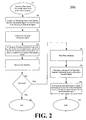
- FIG. 2 illustrates a flowchart 200 that demonstrates one way in which multiple programs can be recorded onto a storage medium using a reduced number or a minimum number of encoding devices.
- a plurality of multimedia inputs can be received. These multimedia inputs can be audio signals, video signals or a combination thereof. Moreover, the invention can receive any number of multimedia inputs.
- these multimedia inputs can be sampled such that the sampled multimedia inputs contain a portion of the plurality of multimedia inputs.
- the resolution of the pictures contained in each of the plurality of multimedia inputs that are sampled can be less than the resolution of the pictures contained in each input prior to the sampling process.
- a number of sampling techniques can be employed to perform this step. As an example, if video is being received, then the resolution of the video signal can be reduced by removing lines of resolution or by removing pixels from the pictures contained in the video signals. If audio is being received, then each audio signal can be sampled or downmixed by removing one or more channels of audio contained in each of the audio signals. It should be noted, however, that the invention is not limited to any particular sampling technique, as any other suitable technique known in the art can be used to sample the incoming multimedia inputs.
- the D1 signals are video signals with a picture resolution of 720 X 480. In some instances, the picture resolution is 704 X 480. These signals can be sampled thereby converting them to 1/2 D1 video signals, i.e., video signals with a picture resolution of 352 X 480. As a result, each of the sampled 1/2 D1 signals contains a portion of its original, corresponding D1 video signal.
- the D1 signals can be sampled down to 1/4 D1 signals or standard input format (SIF) signals with a picture resolution of 352 X 240.
- SIF standard input format
- each audio signal contains four channels of audio.
- These incoming audio signals can be sampled or downmixed to audio signals containing only two channels of audio, i.e ., each audio signal is now a stereo signal.
- the incoming four channel audio signals can be downmixed to audio signals containing only one channel of audio, i.e ., each audio signal is now a mono signal. Similar to the examples relating to the incoming video signals, however, the invention is not limited to the foregoing examples, as any number of incoming audio signals can be sampled or downmixed to any other suitable format or size.
- the sampled inputs can be combined, as shown in step 214. For example, if two D1 signals have been received and sampled down to 1/2 D1 signals, these signals can be combined to create a signal that contains the same number of resolution lines as that typically carried in a full D1 signal. Similarly, if two separate four channel audio signals have been downmixed to two separate stereo signals, then these stereo signals can be combined to create a four channel audio signal.
- a dummy program signal can be generated, which can then be combined with one or more of the incoming sampled video signals to produce a combination of sampled signals in which the combined resolution of the combined signals - including the dummy signal - is equal to that of a D1 signal.
- a dummy program signal can be a video signal that contains no programming, i.e., a blank picture.
- a blank picture i.e., a blank picture.
- the inputs can be encoded, as shown in step 216.
- the number of encoding devices required to encode these sampled signals is less than the number of the original multimedia inputs. For example, if a conventional storage medium device receives two separate D1 video signals, then the storage medium device requires two separate video encoders to encode the D1 signals simultaneously. Likewise, if two separate four channel audio signals are received, then the storage medium device requires two separate audio encoders to encode the two separate four channel audio signals.
- sampling the incoming multimedia inputs reduces the number of encoders normally required to encode the multimedia inputs.
- two D1 video signals are sampled down to 1/2 D1 signals and then combined, then only one video encoder is needed to encode both of these signals simultaneously. This reduces the number of encoders required to perform such a process from two to one.
- four D1 video signals are sampled down to four 1/4 D1 signals and combined, then, again, only one video encoder is needed to encode these 1/4 D1 signals.
- the number of encoders required to encode the sampled multimedia inputs is less than the number of encoders typically required to encode the originally received multimedia inputs and is thus less than the number of multimedia inputs actually received. It should be noted, however, that the invention is not limited to the foregoing examples, as any number of multimedia inputs can be received and sampled down to any other suitable format to reduce the number of encoders needed to encode the incoming multimedia inputs.
- the sampled inputs can then be recorded onto a storage medium, as shown at step 218.
- a determination can then be made as to whether these sampled multimedia inputs can then be played back, as shown at decision block 218. If not, then the process can stop at step 222. If the sampled multimedia inputs are to be played back, then these inputs can be read from the storage medium, as shown at step 224.
- one or more of these multimedia inputs can then be decoded to provide a decoded signal. Specifically, the sampled video signals and the downmixed audio signals can be decoded. These decoded signals can then be processed to enable the display of at least one of the multimedia inputs, as shown at step 228.
- a user can have the option of selecting which of the inputs he wishes to have displayed. For instance, if four 1/4 D1 signals were encoded and recorded onto a storage medium, then the user has the option of viewing any number of the four signals. Those video signals selected for display can then be sent to a display device for viewing while those video signals that are not selected for viewing can be prevented from being displayed.
- the user can have the option of choosing which of the audio signals will be played, including the option of combining any of the audio signals with any of the video signals for display.
- the decoded video signals that are to be displayed can be further processed or upconverted to improve their picture quality.
- the decoded video signals can be upconverted by passing them through a line doubler or any other known device used for improving picture quality.
- flowchart 200 can end at step 230.
Landscapes
- Engineering & Computer Science (AREA)
- Signal Processing (AREA)
- Multimedia (AREA)
- Compression Or Coding Systems Of Tv Signals (AREA)
- Signal Processing For Digital Recording And Reproducing (AREA)
- Television Signal Processing For Recording (AREA)
- Management Or Editing Of Information On Record Carriers (AREA)
Applications Claiming Priority (3)
| Application Number | Priority Date | Filing Date | Title |
|---|---|---|---|
| US916919 | 2001-07-27 | ||
| US09/916,919 US7269334B2 (en) | 2001-07-27 | 2001-07-27 | Recording and playing back multiple programs |
| PCT/US2002/023717 WO2003013152A2 (en) | 2001-07-27 | 2002-07-25 | Recording and playing back multiple programs |
Publications (2)
| Publication Number | Publication Date |
|---|---|
| EP1419659A2 EP1419659A2 (en) | 2004-05-19 |
| EP1419659B1 true EP1419659B1 (en) | 2014-02-26 |
Family
ID=25438080
Family Applications (1)
| Application Number | Title | Priority Date | Filing Date |
|---|---|---|---|
| EP02750316.8A Expired - Lifetime EP1419659B1 (en) | 2001-07-27 | 2002-07-25 | Recording and playing back multiple programs |
Country Status (9)
| Country | Link |
|---|---|
| US (1) | US7269334B2 (enExample) |
| EP (1) | EP1419659B1 (enExample) |
| JP (1) | JP2005519489A (enExample) |
| KR (1) | KR100889155B1 (enExample) |
| CN (1) | CN1295935C (enExample) |
| CA (1) | CA2454783A1 (enExample) |
| MX (1) | MXPA04000743A (enExample) |
| TW (1) | TW577230B (enExample) |
| WO (1) | WO2003013152A2 (enExample) |
Families Citing this family (5)
| Publication number | Priority date | Publication date | Assignee | Title |
|---|---|---|---|---|
| US7312831B2 (en) * | 2003-09-16 | 2007-12-25 | Wegener Communications, Inc. | Re-inserting VBI data using OSD apparatus and method |
| US10152124B2 (en) * | 2006-04-06 | 2018-12-11 | Immersion Corporation | Systems and methods for enhanced haptic effects |
| WO2008031262A1 (en) * | 2006-09-06 | 2008-03-20 | Intel Corporation | A media playing tool with a multiple media playing model |
| US9800905B2 (en) * | 2015-09-14 | 2017-10-24 | Comcast Cable Communications, Llc | Device based audio-format selection |
| CN108989692A (zh) * | 2018-10-19 | 2018-12-11 | 北京微播视界科技有限公司 | 视频拍摄方法、装置、电子设备及计算机可读存储介质 |
Family Cites Families (10)
| Publication number | Priority date | Publication date | Assignee | Title |
|---|---|---|---|---|
| US5093750A (en) * | 1987-11-06 | 1992-03-03 | Samsung Electronics Co., Ltd. | System for recording/reproducing video data on or from a tape medium for storing digital signals and method therein |
| US4967271A (en) * | 1989-04-05 | 1990-10-30 | Ives C. Faroudja | Television scan line doubler including temporal median filter |
| JP2861287B2 (ja) * | 1990-06-15 | 1999-02-24 | キヤノン株式会社 | ディジタル信号処理装置 |
| JP2766919B2 (ja) * | 1991-06-07 | 1998-06-18 | 三菱電機株式会社 | ディジタル信号記録再生装置、ディジタル信号記録装置、ディジタル信号再生装置 |
| WO1993019525A1 (en) * | 1992-03-23 | 1993-09-30 | Euphonix, Inc. | Visual dynamics management for audio instrument |
| IT1270492B (it) | 1993-01-11 | 1997-05-06 | Gragorio Giuseppe | Sistema di composizione di due segnali video in un unico segnale videorisultante, per consentirne la simultanea trasmissione (o videoregistrazione), con un unico trasmettitore (videoregistratore)e successiva decomposizione del segnale risultante nei due segnali video componenti, per consentirne l'utilizzo |
| US5566174A (en) * | 1994-04-08 | 1996-10-15 | Philips Electronics North America Corporation | MPEG information signal conversion system |
| JP3791024B2 (ja) * | 1994-09-12 | 2006-06-28 | 松下電器産業株式会社 | 映像信号記録再生装置 |
| US6430363B2 (en) | 1995-09-11 | 2002-08-06 | Matsushita Electric Industrial Co., Ltd. | Video signal recording and reproducing apparatus |
| JP2000243062A (ja) * | 1999-02-17 | 2000-09-08 | Sony Corp | 映像記録装置および映像記録方法、ならびに集中監視記録システム。 |
-
2001
- 2001-07-27 US US09/916,919 patent/US7269334B2/en not_active Expired - Lifetime
-
2002
- 2002-07-25 CA CA002454783A patent/CA2454783A1/en not_active Abandoned
- 2002-07-25 CN CNB02818176XA patent/CN1295935C/zh not_active Expired - Fee Related
- 2002-07-25 JP JP2003518194A patent/JP2005519489A/ja active Pending
- 2002-07-25 KR KR1020047000873A patent/KR100889155B1/ko not_active Expired - Fee Related
- 2002-07-25 MX MXPA04000743A patent/MXPA04000743A/es not_active Application Discontinuation
- 2002-07-25 WO PCT/US2002/023717 patent/WO2003013152A2/en not_active Ceased
- 2002-07-25 EP EP02750316.8A patent/EP1419659B1/en not_active Expired - Lifetime
- 2002-07-26 TW TW091116744A patent/TW577230B/zh not_active IP Right Cessation
Also Published As
| Publication number | Publication date |
|---|---|
| US7269334B2 (en) | 2007-09-11 |
| TW577230B (en) | 2004-02-21 |
| CN1295935C (zh) | 2007-01-17 |
| WO2003013152A3 (en) | 2004-03-04 |
| JP2005519489A (ja) | 2005-06-30 |
| MXPA04000743A (es) | 2004-04-20 |
| EP1419659A2 (en) | 2004-05-19 |
| CA2454783A1 (en) | 2003-02-13 |
| KR100889155B1 (ko) | 2009-03-17 |
| US20030021589A1 (en) | 2003-01-30 |
| WO2003013152A2 (en) | 2003-02-13 |
| KR20040018486A (ko) | 2004-03-03 |
| CN1555655A (zh) | 2004-12-15 |
Similar Documents
| Publication | Publication Date | Title |
|---|---|---|
| EP0596732B1 (en) | Method per performing special effects in the receiver of a coded moving picture transmission system | |
| KR100461207B1 (ko) | 디지탈영상신호송수신장치 | |
| US5646931A (en) | Recording medium reproduction apparatus and recording medium reproduction method for selecting, mixing and outputting arbitrary two streams from medium including a plurality of high effiency-encoded sound streams recorded thereon | |
| US8594204B2 (en) | Method and device for basic and overlay video information transmission | |
| US20050158022A1 (en) | Editing apparatus and data editing method | |
| JP4642161B2 (ja) | データ復号化装置及びデータ復号化方法 | |
| EP1950962B1 (en) | Transport stream generating apparatus, recording apparatus having the same, and transport stream generating method | |
| US20080199147A1 (en) | Apparatus for reproducing moving image stream with speed change and method thereof | |
| EP1419659B1 (en) | Recording and playing back multiple programs | |
| US20030219041A1 (en) | Method for recording location information of broadcasting signals, and a broadcasting signal receiving device and transmitting device capable of recording location information of broadcasting signals | |
| US20060051060A1 (en) | Method and system for digitally recording broadcast content | |
| JP2001008211A (ja) | デジタルインターフェースを利用した音声ストリーム送受信装置及び方法 | |
| US7480447B2 (en) | Pause time recovery and playback speed-up without loss of picture information | |
| EP1231782A1 (en) | Tuning device for a data distribution network | |
| CN1798348B (zh) | 个人视频记录器系统以及在系统中再现广播信号的方法 | |
| KR20000064963A (ko) | 비디오 이미지를 기록 및 재생하는 방법 및 장치 | |
| US8249432B2 (en) | Video and audio playback apparatus and video and audio playback method | |
| EP1784025A2 (en) | Digital television recorder for recording multiple sets of audio tracks | |
| JPH07177121A (ja) | 情報多重装置 | |
| US7206502B2 (en) | Apparatus and method for recording and reproducing digital data | |
| JP2006319397A (ja) | デジタル記録再生装置 | |
| EP1133171A2 (en) | Multi-media receiver | |
| JP2002112180A (ja) | ディジタルデータ記録再生装置及びその方法 | |
| JP2003101960A (ja) | 映像再生装置 |
Legal Events
| Date | Code | Title | Description |
|---|---|---|---|
| PUAI | Public reference made under article 153(3) epc to a published international application that has entered the european phase |
Free format text: ORIGINAL CODE: 0009012 |
|
| 17P | Request for examination filed |
Effective date: 20040128 |
|
| AK | Designated contracting states |
Kind code of ref document: A2 Designated state(s): AT BE BG CH CY CZ DE DK EE ES FI FR GB GR IE IT LI LU MC NL PT SE SK TR |
|
| AX | Request for extension of the european patent |
Extension state: AL LT LV MK RO SI |
|
| RAP1 | Party data changed (applicant data changed or rights of an application transferred) |
Owner name: THOMSON LICENSING |
|
| 17Q | First examination report despatched |
Effective date: 20090723 |
|
| RAP1 | Party data changed (applicant data changed or rights of an application transferred) |
Owner name: THOMSON LICENSING |
|
| GRAP | Despatch of communication of intention to grant a patent |
Free format text: ORIGINAL CODE: EPIDOSNIGR1 |
|
| INTG | Intention to grant announced |
Effective date: 20130924 |
|
| GRAS | Grant fee paid |
Free format text: ORIGINAL CODE: EPIDOSNIGR3 |
|
| GRAA | (expected) grant |
Free format text: ORIGINAL CODE: 0009210 |
|
| AK | Designated contracting states |
Kind code of ref document: B1 Designated state(s): DE FR GB IT |
|
| REG | Reference to a national code |
Ref country code: GB Ref legal event code: FG4D |
|
| REG | Reference to a national code |
Ref country code: DE Ref legal event code: R096 Ref document number: 60246020 Country of ref document: DE Effective date: 20140403 |
|
| REG | Reference to a national code |
Ref country code: DE Ref legal event code: R084 Ref document number: 60246020 Country of ref document: DE Effective date: 20140401 |
|
| REG | Reference to a national code |
Ref country code: DE Ref legal event code: R097 Ref document number: 60246020 Country of ref document: DE |
|
| PLBE | No opposition filed within time limit |
Free format text: ORIGINAL CODE: 0009261 |
|
| STAA | Information on the status of an ep patent application or granted ep patent |
Free format text: STATUS: NO OPPOSITION FILED WITHIN TIME LIMIT |
|
| 26N | No opposition filed |
Effective date: 20141127 |
|
| REG | Reference to a national code |
Ref country code: DE Ref legal event code: R097 Ref document number: 60246020 Country of ref document: DE Effective date: 20141127 |
|
| GBPC | Gb: european patent ceased through non-payment of renewal fee |
Effective date: 20140725 |
|
| PG25 | Lapsed in a contracting state [announced via postgrant information from national office to epo] |
Ref country code: IT Free format text: LAPSE BECAUSE OF FAILURE TO SUBMIT A TRANSLATION OF THE DESCRIPTION OR TO PAY THE FEE WITHIN THE PRESCRIBED TIME-LIMIT Effective date: 20140226 |
|
| PG25 | Lapsed in a contracting state [announced via postgrant information from national office to epo] |
Ref country code: GB Free format text: LAPSE BECAUSE OF NON-PAYMENT OF DUE FEES Effective date: 20140725 |
|
| REG | Reference to a national code |
Ref country code: FR Ref legal event code: PLFP Year of fee payment: 15 |
|
| REG | Reference to a national code |
Ref country code: FR Ref legal event code: PLFP Year of fee payment: 16 |
|
| REG | Reference to a national code |
Ref country code: DE Ref legal event code: R082 Ref document number: 60246020 Country of ref document: DE Representative=s name: HOFSTETTER, SCHURACK & PARTNER - PATENT- UND R, DE Ref country code: DE Ref legal event code: R082 Ref document number: 60246020 Country of ref document: DE Representative=s name: HOFSTETTER, SCHURACK & PARTNER PATENT- UND REC, DE |
|
| REG | Reference to a national code |
Ref country code: FR Ref legal event code: PLFP Year of fee payment: 17 |
|
| PGFP | Annual fee paid to national office [announced via postgrant information from national office to epo] |
Ref country code: DE Payment date: 20190711 Year of fee payment: 18 Ref country code: FR Payment date: 20190731 Year of fee payment: 18 |
|
| REG | Reference to a national code |
Ref country code: DE Ref legal event code: R119 Ref document number: 60246020 Country of ref document: DE |
|
| PG25 | Lapsed in a contracting state [announced via postgrant information from national office to epo] |
Ref country code: FR Free format text: LAPSE BECAUSE OF NON-PAYMENT OF DUE FEES Effective date: 20200731 |
|
| PG25 | Lapsed in a contracting state [announced via postgrant information from national office to epo] |
Ref country code: DE Free format text: LAPSE BECAUSE OF NON-PAYMENT OF DUE FEES Effective date: 20210202 |