EP1416583A2 - Befestigung einer Antenne auf einem Fahrzeugdach mit Hochspannungsschutz - Google Patents
Befestigung einer Antenne auf einem Fahrzeugdach mit Hochspannungsschutz Download PDFInfo
- Publication number
- EP1416583A2 EP1416583A2 EP03024670A EP03024670A EP1416583A2 EP 1416583 A2 EP1416583 A2 EP 1416583A2 EP 03024670 A EP03024670 A EP 03024670A EP 03024670 A EP03024670 A EP 03024670A EP 1416583 A2 EP1416583 A2 EP 1416583A2
- Authority
- EP
- European Patent Office
- Prior art keywords
- vehicle
- unit
- optical
- units
- signals
- Prior art date
- Legal status (The legal status is an assumption and is not a legal conclusion. Google has not performed a legal analysis and makes no representation as to the accuracy of the status listed.)
- Withdrawn
Links
Images

Classifications
-
- H—ELECTRICITY
- H01—ELECTRIC ELEMENTS
- H01Q—ANTENNAS, i.e. RADIO AERIALS
- H01Q1/00—Details of, or arrangements associated with, antennas
- H01Q1/52—Means for reducing coupling between antennas; Means for reducing coupling between an antenna and another structure
-
- H—ELECTRICITY
- H01—ELECTRIC ELEMENTS
- H01Q—ANTENNAS, i.e. RADIO AERIALS
- H01Q1/00—Details of, or arrangements associated with, antennas
- H01Q1/27—Adaptation for use in or on movable bodies
- H01Q1/32—Adaptation for use in or on road or rail vehicles
- H01Q1/3208—Adaptation for use in or on road or rail vehicles characterised by the application wherein the antenna is used
- H01Q1/3216—Adaptation for use in or on road or rail vehicles characterised by the application wherein the antenna is used where the road or rail vehicle is only used as transportation means
-
- H—ELECTRICITY
- H01—ELECTRIC ELEMENTS
- H01Q—ANTENNAS, i.e. RADIO AERIALS
- H01Q1/00—Details of, or arrangements associated with, antennas
- H01Q1/27—Adaptation for use in or on movable bodies
- H01Q1/32—Adaptation for use in or on road or rail vehicles
- H01Q1/325—Adaptation for use in or on road or rail vehicles characterised by the location of the antenna on the vehicle
- H01Q1/3275—Adaptation for use in or on road or rail vehicles characterised by the location of the antenna on the vehicle mounted on a horizontal surface of the vehicle, e.g. on roof, hood, trunk
-
- H—ELECTRICITY
- H01—ELECTRIC ELEMENTS
- H01Q—ANTENNAS, i.e. RADIO AERIALS
- H01Q3/00—Arrangements for changing or varying the orientation or the shape of the directional pattern of the waves radiated from an antenna or antenna system
- H01Q3/005—Arrangements for changing or varying the orientation or the shape of the directional pattern of the waves radiated from an antenna or antenna system using remotely controlled antenna positioning or scanning
Definitions
- the present invention relates to a system for vehicles comprising a first unit arranged on the outside of the vehicle and a second unit arranged on the inside of the vehicle, and communication means to provide a communication contact between said first and second units.
- the invention relates to systems comprising communication units, such as antennae, mounted on vehicles running in the vicinity of high-voltage lines or supplies, such as train. Further, the invention relates to a corresponding method.
- This satellite antenna comprises e.g. the active antenna, sensors, gyro, mechanical steering and a protective plastic frame (to support from shifting weather conditions, wind and sudden pressure changes from entering tunnels etc).
- the standard method i.e. using thick copper wires as a metal cage to encapsulate the antenna's plastic frame or to include the thick copper wires in the plastic frame, the received signal would be compromised severely in terms of e.g. polarisation and signal strength. This method could be used but only with very high power on received satellite signal, something that would restrict the geographical coverage.
- phase array antennas flat antennas
- a system for vehicles comprising a first unit arranged on the outside of the vehicle and a second unit arranged on the inside of the vehicle, and communication means to provide a communication contact between said first and second units, wherein the communication means provides a galvanic separation between the first and second units.
- the solution is to galvanically separate the equipment on the roof from the equipment inside the train.
- the galvanic separation comprises an optical component
- the communication means comprises an RF/optical converter arranged outside the vehicle, an optical/RF converter arranged inside the vehicle, and an optical fiber connecting said converters.
- the antenna's RF-signal is converted into an optical signal, lead through an optical fiber into the carriage where it is reconverted into a RF-signal for the satellite receiver.
- essentially no distortion is impaired on the signal, and at the same time a very efficient high-voltage protection is achieved.
- Radio-optical transformers are per se previously known, but are heretofore used to relay RF-signals over long distances, since the optical fiber allows almost unlimited fiber lengths compared to the normal coaxial cables, which reduce the signal strength by the meter.
- the first unit arranged on the outside of the vehicle preferably functions as an interface to at least one telecommunications network, said unit preferably comprising an antenna.
- the antenna could be a part of the Icomera system discussed previously.
- the second unit could be operational as a gateway between an local network operating within the vehicle and an external network. Further, the second unit could serve as a, preferably wireless, interface towards further units within the vehicle.
- the first unit is further preferably supplied with power without any galvanic connection to the interior of the vehicle.
- the first unit is supplied with power through a safety 1:1 power transformer.
- the external unit could be supplied with power from within the vehicle, and still maintaining the high-voltage protection of the system.
- an external power supply for the external unit such as an externally mounted electric accumulator.
- the first unit could further be enclosed in a protective casing, said casing being grounded.
- a protective casing said casing being grounded.
- a method for transferring communication signals between an indoor and outdoor environment of a vehicle comprising the steps: providing a first unit in the outdoor environment of the vehicle; providing a second unit in the indoor environment of the vehicle; and transferring communication signals between the first and second units, wherein the communication signals are lead through a galvanic separation.
- the method corresponds to the system according to the invention, as discussed previously, and similar advantages are achieved.
- the invention is especially useful for internet-enabled train solutions.
- the invention is not only relevant for trains but for electric trams, buses, vans, cars etc as well.
- the invention is not only relevant for antennae but for all equipment, especially communication equipment, mounted on top of a vehicle roof with overlying high power lines.
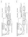
- FIG. 1-4 schematically illustrates different variants of a system for how to mount equipment, in these cases a satellite antenna, onboard train roofs, with maintained high voltage protection and no signal distortion.
- the DC/AC transformer (a) transforms the direct current from the train power supply into alternating current, which is led up on the roof of the train, to the safety power transformer (b), which connects to the AC/DC converter (c) which ultimately feeds the satellite antenna (g) with power.
- the satellite antenna (g) is fed with power from within the train without being galvanically connected to the inside of the train.
- the RF signal from the satellite antenna (g) is converted by the RF/optical converter (f) into an optical signal.
- the signal Led through an optical fiber (optocable (e)) into the train, the signal is converted back by an optical/RF converter (d) into a normal RF signal, ready to attach to the satellite card inside the train.
- the optical fiber (e) the RF signal from the satellite antenna (g), can be relayed into the train without any galvanic connection to the inside of the train.
- the safety power transformer (b), the AC/DC power transformer (c) and the RF/optical converter (f) may be integrated in one box as in Fig 1 and Fig 2.
- the RF/optical converter (f) may be integrated with the satellite antenna (g) as in Fig 3 and Fig 4.
- the box that covers the subunits (h) may be placed inside the train as in Fig 2 and Fig 4 or outside the train as in Fig 1 and Fig 3. Either way, it is preferred that a metal cover is arranged around the components, and to connect the cover to ground.
- the first unit arranged outside the train is in all cases the end unit, i.e. the antenna (g).
- the second unit arranged inside the train in all cases comprises the DC/AC converter (a) and the optical/RF converter (d).
- the other components may be arranged both outside and inside the train, in various combinations.
- the embodiments above relate to trains, but the invention is likewise applicable for other vehicles, and especially vehicles with high-voltage lines in the nearby environment.
- the first unit arranged outside the vehicle is an antenna in the above discussed examples, but may also be any other electronic unit or a combination of several components, and the same applies for the second unit.
- the galvanic separation is preferably an optical component, but other galvanic separation means may be used to this end.
- the communication channel through the galvanic separation as provided by the invention may also be shared by several systems, whereby e.g. the channel may be shared by means of multiplexing.
Landscapes
- Engineering & Computer Science (AREA)
- Remote Sensing (AREA)
- Support Of Aerials (AREA)
- Fittings On The Vehicle Exterior For Carrying Loads, And Devices For Holding Or Mounting Articles (AREA)
- Electric Propulsion And Braking For Vehicles (AREA)
Applications Claiming Priority (2)
| Application Number | Priority Date | Filing Date | Title |
|---|---|---|---|
| SE0203186 | 2002-10-28 | ||
| SE0203186A SE0203186D0 (sv) | 2002-10-28 | 2002-10-28 | Mounting of an antenna on a vehicle roof with maintained high voltage protection |
Publications (2)
| Publication Number | Publication Date |
|---|---|
| EP1416583A2 true EP1416583A2 (de) | 2004-05-06 |
| EP1416583A3 EP1416583A3 (de) | 2004-05-19 |
Family
ID=20289397
Family Applications (1)
| Application Number | Title | Priority Date | Filing Date |
|---|---|---|---|
| EP03024670A Withdrawn EP1416583A3 (de) | 2002-10-28 | 2003-10-28 | Befestigung einer Antenne auf einem Fahrzeugdach mit Hochspannungsschutz |
Country Status (2)
| Country | Link |
|---|---|
| EP (1) | EP1416583A3 (de) |
| SE (1) | SE0203186D0 (de) |
Cited By (4)
| Publication number | Priority date | Publication date | Assignee | Title |
|---|---|---|---|---|
| WO2009085441A1 (en) * | 2007-12-28 | 2009-07-09 | Echostar Technologies Llc | Apparatus and systems for electrically isolating and transmitting rf signals between two devices |
| EP3719924A1 (de) | 2019-04-04 | 2020-10-07 | Icomera Ab | Zugkommunikationssystem mit abgeschirmter antenne |
| SE547639C2 (en) * | 2024-06-13 | 2025-11-04 | Icomera Ab | High voltage protection unit for satellite communication system in railbound vehicles |
| EP4663460A1 (de) | 2024-06-13 | 2025-12-17 | Icomera Ab | Hochspannungsschutzeinheit für satellitenkommunikationssystem in schienengebundenen fahrzeugen |
Family Cites Families (5)
| Publication number | Priority date | Publication date | Assignee | Title |
|---|---|---|---|---|
| JPS57166750A (en) * | 1981-04-07 | 1982-10-14 | Sumitomo Electric Ind Ltd | Communication device |
| JP3411947B2 (ja) * | 1995-08-08 | 2003-06-03 | シャープ株式会社 | 電波−光変換変調装置及びそれを用いた通信システム |
| JP3737896B2 (ja) * | 1997-11-28 | 2006-01-25 | 株式会社日立国際電気 | 中継システム |
| US6577419B1 (en) * | 1998-12-18 | 2003-06-10 | Christopher J. Hall | Optical-frequency communications system for aircraft |
| US20020181668A1 (en) * | 2001-06-01 | 2002-12-05 | Lee Masoian | Method and system for radio frequency/fiber optic antenna interface |
-
2002
- 2002-10-28 SE SE0203186A patent/SE0203186D0/xx unknown
-
2003
- 2003-10-28 EP EP03024670A patent/EP1416583A3/de not_active Withdrawn
Cited By (10)
| Publication number | Priority date | Publication date | Assignee | Title |
|---|---|---|---|---|
| WO2009085441A1 (en) * | 2007-12-28 | 2009-07-09 | Echostar Technologies Llc | Apparatus and systems for electrically isolating and transmitting rf signals between two devices |
| US7856207B2 (en) | 2007-12-28 | 2010-12-21 | Echostar Technologies L.L.C. | Apparatus and systems for electrically isolating and transmitting RF signals between two devices |
| US7899395B2 (en) | 2007-12-28 | 2011-03-01 | Echostar Technologies L.L.C. | Apparatus and systems for electrically isolating a receiver from an antenna |
| US8170479B2 (en) | 2007-12-28 | 2012-05-01 | Echostar Technologies L.L.C. | Apparatus and systems for electrically isolating multiple devices |
| EP3719924A1 (de) | 2019-04-04 | 2020-10-07 | Icomera Ab | Zugkommunikationssystem mit abgeschirmter antenne |
| SE547639C2 (en) * | 2024-06-13 | 2025-11-04 | Icomera Ab | High voltage protection unit for satellite communication system in railbound vehicles |
| SE2450649A1 (en) * | 2024-06-13 | 2025-11-04 | Icomera Ab | High voltage protection unit for satellite communication system in railbound vehicles |
| SE2550571A1 (en) * | 2024-06-13 | 2025-12-14 | Icomera Ab | High voltage protection unit for satellite communication system in railbound vehicles |
| EP4663460A1 (de) | 2024-06-13 | 2025-12-17 | Icomera Ab | Hochspannungsschutzeinheit für satellitenkommunikationssystem in schienengebundenen fahrzeugen |
| EP4663458A1 (de) | 2024-06-13 | 2025-12-17 | Icomera Ab | Drahtloses kommunikationssystem für elektrisch betriebene schienengebundene fahrzeuge |
Also Published As
| Publication number | Publication date |
|---|---|
| SE0203186D0 (sv) | 2002-10-28 |
| EP1416583A3 (de) | 2004-05-19 |
Similar Documents
| Publication | Publication Date | Title |
|---|---|---|
| US6889042B2 (en) | Cellular mobile telephone system usable on board a passenger transport vehicle | |
| US6433749B1 (en) | Antenna assembly | |
| US8508419B2 (en) | Multiple antenna element system and method | |
| US20020008667A1 (en) | Glass-mountable antenna system with DC and RF coupling | |
| CN102290634B (zh) | 车载天线系统和方法 | |
| US20160255310A1 (en) | System for data collection and data transfer from a vehicle | |
| US20100173522A1 (en) | Adapter for a coaxial cable | |
| EP1265442A1 (de) | Video-und Tonsignaleübertragungssytem für Eisenbahnen | |
| US20050113060A1 (en) | Wireless network system | |
| US11056842B2 (en) | Jumper cable with capacitive power enhancement and/or overvoltage protection | |
| RU2405699C1 (ru) | Центральная управляющая система контроля безопасности и связи пассажирского поезда | |
| US20120275752A1 (en) | Insulation pressure-resistance cylinder body of submarine cable equipment, submarine cable equipment, and manufacturing method | |
| JP2006197164A (ja) | データ伝送システム | |
| EP4478538A1 (de) | Eingebaute antenne | |
| WO1990009041A1 (en) | Combined mirror and aerial installation for vehicles | |
| US20220231466A1 (en) | Hybrid cable assembly with circuit breaking device for overvoltage protection | |
| US7501988B2 (en) | Antenna device for a motor vehicle and the respective motor vehicle | |
| CN209592289U (zh) | 一种智能车载天线 | |
| JPH11266251A (ja) | 車両内配線装置 | |
| CN1053071C (zh) | 列车线路系统应用的电磁通信链路 | |
| US20220166493A1 (en) | Antenna device, integrated communication device, and wireless communication device | |
| RU2650732C2 (ru) | Антенна транспортного средства для мобильных служб | |
| RU2579603C1 (ru) | Центральная управляющая система системы контроля безопасности и связи пассажирского поезда | |
| EP1416583A3 (de) | Befestigung einer Antenne auf einem Fahrzeugdach mit Hochspannungsschutz | |
| WO2012138249A1 (en) | Passenger train antenna module (embodiments) and antenna module heating device |
Legal Events
| Date | Code | Title | Description |
|---|---|---|---|
| PUAI | Public reference made under article 153(3) epc to a published international application that has entered the european phase |
Free format text: ORIGINAL CODE: 0009012 |
|
| PUAL | Search report despatched |
Free format text: ORIGINAL CODE: 0009013 |
|
| AK | Designated contracting states |
Kind code of ref document: A2 Designated state(s): AT BE BG CH CY CZ DE DK EE ES FI FR GB GR HU IE IT LI LU MC NL PT RO SE SI SK TR |
|
| AX | Request for extension of the european patent |
Extension state: AL LT LV MK |
|
| AK | Designated contracting states |
Kind code of ref document: A3 Designated state(s): AT BE BG CH CY CZ DE DK EE ES FI FR GB GR HU IE IT LI LU MC NL PT RO SE SI SK TR |
|
| AX | Request for extension of the european patent |
Extension state: AL LT LV MK |
|
| 17P | Request for examination filed |
Effective date: 20041029 |
|
| 17Q | First examination report despatched |
Effective date: 20041227 |
|
| AKX | Designation fees paid |
Designated state(s): AT BE BG CH CY CZ DE DK EE ES FI FR GB GR HU IE IT LI LU MC NL PT RO SE SI SK TR |
|
| GRAP | Despatch of communication of intention to grant a patent |
Free format text: ORIGINAL CODE: EPIDOSNIGR1 |
|
| RTI1 | Title (correction) |
Free format text: MOUNING OF AN ANTENNA ON A TRAIN ROOF WITH MAINTAINED HIGH VOLTAGE PROTECTION |
|
| STAA | Information on the status of an ep patent application or granted ep patent |
Free format text: STATUS: THE APPLICATION IS DEEMED TO BE WITHDRAWN |
|
| 18D | Application deemed to be withdrawn |
Effective date: 20060915 |