EP1416113A2 - Rahmen mit einem Abdeckprofil - Google Patents
Rahmen mit einem Abdeckprofil Download PDFInfo
- Publication number
- EP1416113A2 EP1416113A2 EP03078423A EP03078423A EP1416113A2 EP 1416113 A2 EP1416113 A2 EP 1416113A2 EP 03078423 A EP03078423 A EP 03078423A EP 03078423 A EP03078423 A EP 03078423A EP 1416113 A2 EP1416113 A2 EP 1416113A2
- Authority
- EP
- European Patent Office
- Prior art keywords
- frame
- cover profile
- frame member
- cover
- profile
- Prior art date
- Legal status (The legal status is an assumption and is not a legal conclusion. Google has not performed a legal analysis and makes no representation as to the accuracy of the status listed.)
- Withdrawn
Links
Images


Classifications
-
- E—FIXED CONSTRUCTIONS
- E06—DOORS, WINDOWS, SHUTTERS, OR ROLLER BLINDS IN GENERAL; LADDERS
- E06B—FIXED OR MOVABLE CLOSURES FOR OPENINGS IN BUILDINGS, VEHICLES, FENCES OR LIKE ENCLOSURES IN GENERAL, e.g. DOORS, WINDOWS, BLINDS, GATES
- E06B1/00—Border constructions of openings in walls, floors, or ceilings; Frames to be rigidly mounted in such openings
- E06B1/04—Frames for doors, windows, or the like to be fixed in openings
- E06B1/36—Frames uniquely adapted for windows
- E06B1/366—Mullions or transoms therefor
-
- E—FIXED CONSTRUCTIONS
- E06—DOORS, WINDOWS, SHUTTERS, OR ROLLER BLINDS IN GENERAL; LADDERS
- E06B—FIXED OR MOVABLE CLOSURES FOR OPENINGS IN BUILDINGS, VEHICLES, FENCES OR LIKE ENCLOSURES IN GENERAL, e.g. DOORS, WINDOWS, BLINDS, GATES
- E06B1/00—Border constructions of openings in walls, floors, or ceilings; Frames to be rigidly mounted in such openings
- E06B1/04—Frames for doors, windows, or the like to be fixed in openings
- E06B1/26—Frames of plastics
- E06B1/30—Frames of plastics composed of several parts with respect to the cross-section of the frame itself
-
- E—FIXED CONSTRUCTIONS
- E06—DOORS, WINDOWS, SHUTTERS, OR ROLLER BLINDS IN GENERAL; LADDERS
- E06B—FIXED OR MOVABLE CLOSURES FOR OPENINGS IN BUILDINGS, VEHICLES, FENCES OR LIKE ENCLOSURES IN GENERAL, e.g. DOORS, WINDOWS, BLINDS, GATES
- E06B1/00—Border constructions of openings in walls, floors, or ceilings; Frames to be rigidly mounted in such openings
- E06B1/04—Frames for doors, windows, or the like to be fixed in openings
- E06B1/34—Coverings, e.g. protecting against weather, for decorative purposes
-
- E—FIXED CONSTRUCTIONS
- E06—DOORS, WINDOWS, SHUTTERS, OR ROLLER BLINDS IN GENERAL; LADDERS
- E06B—FIXED OR MOVABLE CLOSURES FOR OPENINGS IN BUILDINGS, VEHICLES, FENCES OR LIKE ENCLOSURES IN GENERAL, e.g. DOORS, WINDOWS, BLINDS, GATES
- E06B3/00—Window sashes, door leaves, or like elements for closing wall or like openings; Layout of fixed or moving closures, e.g. windows in wall or like openings; Features of rigidly-mounted outer frames relating to the mounting of wing frames
- E06B3/04—Wing frames not characterised by the manner of movement
- E06B3/06—Single frames
- E06B3/08—Constructions depending on the use of specified materials
- E06B3/20—Constructions depending on the use of specified materials of plastics
- E06B3/22—Hollow frames
- E06B3/221—Hollow frames with the frame member having local reinforcements in some parts of its cross-section or with a filled cavity
- E06B3/222—Hollow frames with the frame member having local reinforcements in some parts of its cross-section or with a filled cavity with internal prefabricated reinforcing section members inserted after manufacturing of the hollow frame
Definitions
- the invention relates to a frame, for instance for a window or a door.
- GB-A-2 285 828 describes a frame with frame members on which cover profiles can be arranged. These cover profiles give the frame member a specific appearance. Using such a frame it is possible to use standard frame members and only change the cover profiles when a different appearance is desired.
- single-walled cover profiles are described in this publication which, seen in cross-section, are provided at both ends with fixing means. The drawback of such single-walled profiles is that they deform easily. This has the advantage that fixing of such a profile can be carried out easily. In the course of time however, the form of such a cover profile will change due to weather influences, whereby the cover profiles no longer fit properly and the desired design disappears.
- EP-A-0 812 974 describes a frame with a cover profile which takes a double-walled form.
- a cover profile of stable form is hereby obtained.
- This profile is however only provided with fixing means on one side. This results in the danger of the cover profile moving outward on the opposite side of the frame profile.
- With such a double-walled cover profile it is not possible to arrange fixing means on both sides, since deformation of the cover profile is practically impossible.
- a frame which comprises at least one frame member, at least one hollow cover profile arranged on the frame member, and first fixing means for fixing the position of the cover profile and for preventing a rotation of the cover profile in longitudinal direction, wherein the cover profile further comprises at least one positioning protrusion for at least partly positioning the cover profile relative to the frame member.
- the positioning protrusion ensures that parts of the cover profile can no longer bend away from the frame member. A good fitting of the cover profile on the frame member is hereby obtained at all times.
- the fixing means comprise a groove and a strip hooking therein.
- a fixing can correspond with the usual fixing method for glazing beads in such frames.
- the cover profiles can therefore be released easily and replaced, for instance after some time, by cover profiles with a different appearance.
- the at least one cover profile has a substantially elongate cross-section and the first fixing means are arranged at least close to a first end surface and the positioning protrusion is arranged at least close to a second end surface.
- the at least one cover profile comprises at least one barb means which is operative in a direction opposite to the fastening direction of the first fixing means.
- This barb means ensures that, when the cover profile is attached, it is arranged fitting properly against the frame member and can then no longer bend back. A good fitting of the cover profile against the frame member is hereby obtained, at least in the fixing direction.
- At least one frame member is hollow and comprises at least two cavities separated from each other.
- a frame member with a better form retention is hereby obtained compared to a frame member with only one cavity, whereby the fitting of a cover profile to such a frame member is better guaranteed.
- a strengthening beam is arranged in a first cavity. Sag is reduced by such a strengthening beam, particularly in the case of frames with a large span.
- first channel which debouches, from the second cavity, on a first side of the frame member
- second channel which debouches, from the second cavity, on a second side of the frame member
- a good ventilation and water removal from a frame according to the invention are hereby achieved without the cavity, in which a possible strengthening beam is arranged, on the one hand being exposed to moisture while on the other the moisture does not drain onto a cover profile.
- the invention further relates to a frame, for instance for a window or a door, which frame comprises at least one frame member, at least one hollow cover profile arranged on the frame member and fixing means for positioning the cover profile relative to the frame member.
- the frame member comprises a recess, and at least a part of the cover profile is adapted to the cross-section of the recess in order to position the cover profile relative to the frame member.
- the cover profile can thus be pressed into the recess, and the cover profile is thereby positioned relative to the frame member.
- the frame member is provided with a groove
- the cover profile comprises a rib which protrudes into the groove.
- the groove and/or the rib can be provided with a toothing in order to clamp the rib in the groove. Owing to this toothing the rib is clamped fixedly in the groove, whereby it is no longer easy to remove.
- a glue layer is applied between a cover profile and the frame member. A strong connection is also provided with this glue layer.
- Yet another embodiment of the frame comprises a double-sided adhesive tape which is arranged between the cover profile and the frame member.
- the adhesive tape can be used to attach the cover profile permanently to the frame member, or can be used as assist means during curing of a glue layer.
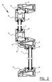
- Figure 1 shows a cross-sectional view of a double frame according to the invention.
- Figure 2 shows a cross-sectional view of a variant of the frame according to figure 1.
- Figure 3 shows a cross-sectional view of a lower frame member of a frame according to figure 1.
- Figure 4 shows a cross-sectional view of an intermediate frame member of a frame according to figure 1.
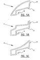
- Figures 5A-5C show different cross-sectional views of cover profiles.
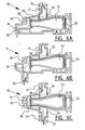
- Figures 6A-6C show cross-sectional views of different frame members provided with a strengthening beam.
- Figure 7 is a cross-sectional view of an intermediate frame member according to the invention.
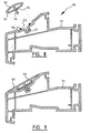
- Figure 8 is a cross-sectional view of an embodiment of a frame according to the invention.
- Figure 9 is a cross-sectional view of a variant of the frame member of figure 8.
- Figure 10 shows a second variant of the frame member of figure 8.
- Figure 11 shows a third variant of the frame member of figure 8.
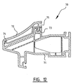
- Figure 12 shows a fourth variant of the frame member.
- FIG. 1 shows a cross-sectional view of an embodiment of a frame 1 according to the invention.
- This frame 1 has an upper frame member 2, a middle frame member 3 and a lower frame member 4. Between the middle frame member 3 and lower frame member 4 is arranged a fixed double glazing unit 5. Between the upper frame member 2 and middle frame member 3 there is arranged a second frame 6 which is arranged hingedly and in which there is again arranged a double glazing unit 7. The windows 5, 7 are secured in the respective frames by means of glazing beads 8.
- cover profiles 9 are arranged on the different frame members 2, 3, 4.
- the cover profiles can further be arranged on the vertical frame members (not shown). It can be advantageous in such a case to mutually connect into a framework the cover profiles of the different frame members. This connection can be effected by means of mechanical coupling means or by means of welding. Connecting of these cover profiles has the further advantage that they can be taken integrally out of the frame relatively quickly and replaced by a framework of cover profiles of different form.
- FIG. 2 shows a variant of a frame 10 according to the invention. Corresponding parts are designated with the same reference numerals.
- the hingedly arranged window frame 6 is arranged on the other side of frame 10.
- the standard frame members 2, 3, 4 are used here, wherein frame members 2, 3 are adapted by means of a reverse profile 11 such that frame 6 can be arranged on the other side.
- a whole additional insert frame is placed to thus allow for instance a window to swing open on the other side.
- the light-transmitting area is hereby limited.
- cover profile 15 which differs in form from cover profiles 9.
- Cover profile 15 has a wall 16 whereby a cavity 17 is created.
- Cover profile 15 is fixed to lower member 4 by means of a fastening tongue 18 which protrudes into cavity 19 of this lower member.
- a part of wall 16 herein lies against a part of lower member 4.
- Cover profile 15 is hereby fixed in position and rotation is prevented.
- a positioning rib 20 which drops into a groove 21 of frame member 4. This ensures that this end surface on which the rib 20 is arranged does not slide and therefore does not move away from frame member 4, and a smooth surface is obtained.
- Cover profile 15 further comprises a barbed lip 22 which hooks behind a rib 23 on frame member 4. This barbed lip 22 ensures that cover profile 15 cannot be removed easily in the removal direction A. A close fit of cover profile 15 against frame member 4 is thus ensured.
- Barbed lip 22 further provides a certain bias whereby cover profile 15 again fits closely against frame member 4 and a smooth outer surface is thus obtained. Although it is recommended to obtain a completely smooth surface between cover profile and frame member, it is also possible to opt for a stepped connection of the cover profile on the frame member. The height difference may only be a few tenths of a millimetre here. This prevents a shadow edge being created at the position of the transition between cover profile and frame member.
- FIG. 4 shows the middle frame member 3.
- Two cover profiles 9 are arranged on this middle frame member 3. These cover profiles 9 only differ in shape from the cover profile 15. Corresponding parts are therefore designated with the same reference numerals.
- FIGS 5A-5C show different cover profiles 9, 15, 25 which are functionally the same and only differ in shape. All cover profiles herein have a fastening tongue 18, a positioning rib 20 and a barbed lip 22.
- FIGS 6A-6C show three different embodiments of frame members 30, 31, 32.
- Each frame member 30, 31, 32 has a cavity 19 for fastening a cover profile and a groove 21 into which drops the positioning rib of a cover profile according to the invention.
- All these frame members 30, 31, 32 have a first cavity 33 in which a strengthening beam 34 is arranged.
- a strengthening beam 34 is usually manufactured from steel and gives the frame members 30, 31, 32 extra strength.
- openings 35 are provided in frame members 30, 31, 32 so that ventilating air or moisture can flow from the one side of frame member 30, 31, 32 to the other side via second cavities 36.
- Figure 7 shows an intermediate frame member 40 on which a cover profile 15 is arranged.
- a reverse profile 11, as already shown in figure 2, is further arranged on frame member 40. With such a reverse profile 11, which engages in the same cavity 19 as cover profiles 15, the intermediate member 40 is made suitable for hinged frames on the outside.
- Frame member 40 has a first cavity 33 in which a strengthening beam can be arranged.
- Frame member 40 further comprises second cavities 36 which are mutually connected by means of openings 35 and thus allow ventilation.
- Figure 8 shows a frame 50 comprising a frame member 51 and a cover profile 52.
- Frame member 51 is provided with a recess 53 into which fits a part 54.
- the shape of part 54 is adapted to the recess 53.
- Cover profile 52 is provided with a rib 55 which is provided with a toothing 56. This rib 55 protrudes into a groove 57, which is likewise provided with a toothing.
- a glue layer 58 is applied between frame member 51 and cover profile 52.
- Figure 9 shows the same frame member 51 and a variant of cover profile 59.
- This cover profile 59 has a flat upper surface 60, thereby changing the appearance of frame 50.
- Figure 10 shows a cross-sectional view, once again of the same frame member 51 having thereon a second variant of a cover profile 61.
- the upper surface of cover profile 61 here takes a stepped form, thereby changing the appearance of the frame once again.
- Figure 11 shows a variant corresponding most closely to the variant of figure 8.
- the same frame member 51 is used but the cover profile 62 differs from cover profile 52.
- Cover profile 62 is provided with a rib 63 which is completely smooth. This smooth rib 63 is inserted into groove 57 which is still provided with a toothing.
- an adhesive tape 64 which positions the cover profile 62 in frame member 51 during curing of the glue 58.
- FIG 12 shows yet another embodiment of a frame 70 according to the invention.
- a frame member 71 is provided on which a cover profile 72 is arranged.
- the cover profile has a fastening tongue 73 with which cover profile 72 is fixed in member 71.
- Cover profile 72 is further provided with a positioning lip 74 which prevents the possibility of cover profile 72 moving away from frame member 71.
- cover profile 72 Further provided in cover profile 72 is a cavity 75 in which a glazing gasket can be placed.
Applications Claiming Priority (2)
| Application Number | Priority Date | Filing Date | Title |
|---|---|---|---|
| NL1021799A NL1021799C2 (nl) | 2002-10-31 | 2002-10-31 | Kozijn met afdekprofiel. |
| NL1021799 | 2002-10-31 |
Publications (2)
| Publication Number | Publication Date |
|---|---|
| EP1416113A2 true EP1416113A2 (de) | 2004-05-06 |
| EP1416113A3 EP1416113A3 (de) | 2005-02-23 |
Family
ID=32089845
Family Applications (1)
| Application Number | Title | Priority Date | Filing Date |
|---|---|---|---|
| EP03078423A Withdrawn EP1416113A3 (de) | 2002-10-31 | 2003-10-30 | Rahmen mit einem Abdeckprofil |
Country Status (2)
| Country | Link |
|---|---|
| EP (1) | EP1416113A3 (de) |
| NL (1) | NL1021799C2 (de) |
Cited By (3)
| Publication number | Priority date | Publication date | Assignee | Title |
|---|---|---|---|---|
| GB2472473A (en) * | 2009-08-03 | 2011-02-09 | Amx Automation Technologies Gmbh | Window frame with drainage pipe |
| GB2511166A (en) * | 2012-12-07 | 2014-08-27 | Porta Bauelemente & Mehr Gmbh & Co Kg | Profiled elements made of plastic material as well as casements and casement frames made of such a profiled element |
| CN106150275A (zh) * | 2016-08-29 | 2016-11-23 | 四川齐飞铝业有限公司 | 一种单向通风防水的断桥铝型材 |
Citations (9)
| Publication number | Priority date | Publication date | Assignee | Title |
|---|---|---|---|---|
| DE1509683A1 (de) * | 1965-07-26 | 1970-04-16 | Meta Plast Maschinen Und Vorri | Profilmaterial als Bauelement,insbesondere fuer Rahmen,Pfosten und Querstreben von Fenstern,Tueren oder Trennwaenden |
| DE2522201A1 (de) * | 1975-05-17 | 1976-12-02 | Wolff & Mueller Hausbau Gmbh | Vorgefertigtes wandbauteil |
| EP0010086A1 (de) * | 1977-07-19 | 1980-04-30 | Jon Karlsson | Bauelement für gebäude. |
| NL8002550A (nl) * | 1980-05-02 | 1981-12-01 | Stamicarbon | Werkwijze voor het vervaardigen van een kunststofkozijn; kunststofprofiel, kunststofkozijn uit deze kunststofprofielen en samengesteld kunststofkozijn uit deze kunststofkozijnen. |
| DE3605090A1 (de) * | 1986-02-18 | 1987-08-20 | Erbsloeh Julius & August | Profilleiste zur unterbrechung der sichtflaeche |
| US5182880A (en) * | 1991-11-18 | 1993-02-02 | New Morning Windows, Inc. | Door frame cladding apparatus |
| EP0674081A2 (de) * | 1994-03-23 | 1995-09-27 | Thyssen Polymer Gmbh | Fenster |
| EP0812974A2 (de) * | 1996-06-15 | 1997-12-17 | Thyssen Polymer Gmbh | Kunststoffrahmen für Fenster, Türen oder dergl |
| EP0967356A2 (de) * | 1998-06-25 | 1999-12-29 | Gebrüder Kömmerling Kunststoffwerke GmbH | Vorrichtung zum Verschliessen einer Gebäudeöffnung |
Family Cites Families (1)
| Publication number | Priority date | Publication date | Assignee | Title |
|---|---|---|---|---|
| GB2285828B (en) | 1994-01-19 | 1996-12-04 | Besford Holdings Ltd | Improvements in or relating to windows and doors |
-
2002
- 2002-10-31 NL NL1021799A patent/NL1021799C2/nl not_active IP Right Cessation
-
2003
- 2003-10-30 EP EP03078423A patent/EP1416113A3/de not_active Withdrawn
Patent Citations (9)
| Publication number | Priority date | Publication date | Assignee | Title |
|---|---|---|---|---|
| DE1509683A1 (de) * | 1965-07-26 | 1970-04-16 | Meta Plast Maschinen Und Vorri | Profilmaterial als Bauelement,insbesondere fuer Rahmen,Pfosten und Querstreben von Fenstern,Tueren oder Trennwaenden |
| DE2522201A1 (de) * | 1975-05-17 | 1976-12-02 | Wolff & Mueller Hausbau Gmbh | Vorgefertigtes wandbauteil |
| EP0010086A1 (de) * | 1977-07-19 | 1980-04-30 | Jon Karlsson | Bauelement für gebäude. |
| NL8002550A (nl) * | 1980-05-02 | 1981-12-01 | Stamicarbon | Werkwijze voor het vervaardigen van een kunststofkozijn; kunststofprofiel, kunststofkozijn uit deze kunststofprofielen en samengesteld kunststofkozijn uit deze kunststofkozijnen. |
| DE3605090A1 (de) * | 1986-02-18 | 1987-08-20 | Erbsloeh Julius & August | Profilleiste zur unterbrechung der sichtflaeche |
| US5182880A (en) * | 1991-11-18 | 1993-02-02 | New Morning Windows, Inc. | Door frame cladding apparatus |
| EP0674081A2 (de) * | 1994-03-23 | 1995-09-27 | Thyssen Polymer Gmbh | Fenster |
| EP0812974A2 (de) * | 1996-06-15 | 1997-12-17 | Thyssen Polymer Gmbh | Kunststoffrahmen für Fenster, Türen oder dergl |
| EP0967356A2 (de) * | 1998-06-25 | 1999-12-29 | Gebrüder Kömmerling Kunststoffwerke GmbH | Vorrichtung zum Verschliessen einer Gebäudeöffnung |
Cited By (6)
| Publication number | Priority date | Publication date | Assignee | Title |
|---|---|---|---|---|
| GB2472473A (en) * | 2009-08-03 | 2011-02-09 | Amx Automation Technologies Gmbh | Window frame with drainage pipe |
| GB2472473B (en) * | 2009-08-03 | 2014-09-10 | Amx Automation Technologies Gmbh | Plastic profile |
| GB2511166A (en) * | 2012-12-07 | 2014-08-27 | Porta Bauelemente & Mehr Gmbh & Co Kg | Profiled elements made of plastic material as well as casements and casement frames made of such a profiled element |
| DK178833B1 (da) * | 2012-12-07 | 2017-03-06 | Porta Bauelemente & Mehr Gmbh & Co Kg | Profilelement af kunststof samt vinduesfløj og vinduesramme bestående af et sådant profilelement |
| GB2511166B (en) * | 2012-12-07 | 2019-02-13 | Porta Bauelemente & Mehr Gmbh & Co Kg | Profiled elements made of plastic material as well as casements and casement frames made of such a profiled element |
| CN106150275A (zh) * | 2016-08-29 | 2016-11-23 | 四川齐飞铝业有限公司 | 一种单向通风防水的断桥铝型材 |
Also Published As
| Publication number | Publication date |
|---|---|
| NL1021799C2 (nl) | 2004-05-14 |
| EP1416113A3 (de) | 2005-02-23 |
Similar Documents
| Publication | Publication Date | Title |
|---|---|---|
| US6640508B2 (en) | Roof window assembly and components | |
| US5802790A (en) | Decorative moulding corner cap | |
| AU2007313070B2 (en) | Barrier assembly for building openings | |
| US4038791A (en) | Window greenhouse | |
| AU2009260760B2 (en) | Sealing membrane for sealing gaps between frames of a window and rough openings | |
| US20050115178A1 (en) | Corner key for connecting profiles together and frame work assembly | |
| JP4113884B2 (ja) | 幕板およびその幕板を用いた外壁施工構造 | |
| JPH07501862A (ja) | 天窓(スカイライト)アセンブリ | |
| US6276101B1 (en) | Door and window surround | |
| US6463707B1 (en) | Decorative trim assemblies | |
| EP1416113A2 (de) | Rahmen mit einem Abdeckprofil | |
| US8359800B2 (en) | Shutter border frame with channel and cover plug | |
| US20070245649A1 (en) | Exterior casing trim | |
| EP0990761A2 (de) | Holz-Aluminium-Rahmen für Fenster | |
| EP1146194A2 (de) | Profilierte Tür, Fenster oder dergleichen | |
| AU2009238345A1 (en) | Improvements in and relating to doors | |
| GB2110284A (en) | Frame member for doors and windows | |
| GB2292411A (en) | Window bar joint cover | |
| US20120144747A1 (en) | Light-blocking window shutter | |
| JP3276224B2 (ja) | 窓枠構造及びその施工方法 | |
| JPS6378953A (ja) | 外壁板の接合構造 | |
| JP2022051947A (ja) | 押縁用接続部材および建具 | |
| AU712941B2 (en) | Fixing windows in window openings | |
| JP2003184212A (ja) | 外 壁 | |
| AU2004200347A1 (en) | A Flashing |
Legal Events
| Date | Code | Title | Description |
|---|---|---|---|
| PUAI | Public reference made under article 153(3) epc to a published international application that has entered the european phase |
Free format text: ORIGINAL CODE: 0009012 |
|
| AK | Designated contracting states |
Kind code of ref document: A2 Designated state(s): AT BE BG CH CY CZ DE DK EE ES FI FR GB GR HU IE IT LI LU MC NL PT RO SE SI SK TR |
|
| AX | Request for extension of the european patent |
Extension state: AL LT LV MK |
|
| PUAL | Search report despatched |
Free format text: ORIGINAL CODE: 0009013 |
|
| AK | Designated contracting states |
Kind code of ref document: A3 Designated state(s): AT BE BG CH CY CZ DE DK EE ES FI FR GB GR HU IE IT LI LU MC NL PT RO SE SI SK TR |
|
| AX | Request for extension of the european patent |
Extension state: AL LT LV MK |
|
| RIC1 | Information provided on ipc code assigned before grant |
Ipc: 7E 06B 3/30 B Ipc: 7E 06B 1/30 A |
|
| 17P | Request for examination filed |
Effective date: 20050627 |
|
| AKX | Designation fees paid |
Designated state(s): AT BE BG CH CY CZ DE DK EE ES FI FR GB GR HU IE IT LI LU MC NL PT RO SE SI SK TR |
|
| AXX | Extension fees paid |
Extension state: MK Payment date: 20050823 Extension state: LV Payment date: 20050823 Extension state: LT Payment date: 20050823 Extension state: AL Payment date: 20050823 |
|
| STAA | Information on the status of an ep patent application or granted ep patent |
Free format text: STATUS: THE APPLICATION IS DEEMED TO BE WITHDRAWN |
|
| 18D | Application deemed to be withdrawn |
Effective date: 20070503 |