EP1416084A1 - System und Verfahren zur Zuführung einer Faserstoffsuspension in einem Stoffauflauf - Google Patents
System und Verfahren zur Zuführung einer Faserstoffsuspension in einem Stoffauflauf Download PDFInfo
- Publication number
- EP1416084A1 EP1416084A1 EP03022309A EP03022309A EP1416084A1 EP 1416084 A1 EP1416084 A1 EP 1416084A1 EP 03022309 A EP03022309 A EP 03022309A EP 03022309 A EP03022309 A EP 03022309A EP 1416084 A1 EP1416084 A1 EP 1416084A1
- Authority
- EP
- European Patent Office
- Prior art keywords
- dilution
- headbox
- dilution liquid
- liquid
- fiber suspension
- Prior art date
- Legal status (The legal status is an assumption and is not a legal conclusion. Google has not performed a legal analysis and makes no representation as to the accuracy of the status listed.)
- Granted
Links
- 239000000725 suspension Substances 0.000 title claims abstract description 117
- 238000000034 method Methods 0.000 title claims description 16
- 238000010790 dilution Methods 0.000 claims abstract description 228
- 239000012895 dilution Substances 0.000 claims abstract description 228
- 239000000835 fiber Substances 0.000 claims abstract description 85
- 239000007788 liquid Substances 0.000 claims description 110
- 238000013022 venting Methods 0.000 claims description 52
- XLYOFNOQVPJJNP-UHFFFAOYSA-N water Substances O XLYOFNOQVPJJNP-UHFFFAOYSA-N 0.000 claims description 46
- 239000000463 material Substances 0.000 claims description 13
- 238000004140 cleaning Methods 0.000 claims description 12
- 239000010865 sewage Substances 0.000 claims description 6
- 230000001105 regulatory effect Effects 0.000 abstract description 5
- 239000012530 fluid Substances 0.000 abstract 2
- 230000000712 assembly Effects 0.000 abstract 1
- 238000000429 assembly Methods 0.000 abstract 1
- 230000001419 dependent effect Effects 0.000 abstract 1
- 239000000203 mixture Substances 0.000 abstract 1
- 238000009423 ventilation Methods 0.000 description 17
- 238000007726 management method Methods 0.000 description 7
- 238000005192 partition Methods 0.000 description 4
- 239000003085 diluting agent Substances 0.000 description 3
- 239000000123 paper Substances 0.000 description 3
- 239000010410 layer Substances 0.000 description 2
- 238000004519 manufacturing process Methods 0.000 description 2
- 239000011111 cardboard Substances 0.000 description 1
- 230000001276 controlling effect Effects 0.000 description 1
- 238000007872 degassing Methods 0.000 description 1
- 238000007865 diluting Methods 0.000 description 1
- 238000005516 engineering process Methods 0.000 description 1
- 239000013505 freshwater Substances 0.000 description 1
- 239000008240 homogeneous mixture Substances 0.000 description 1
- 238000012544 monitoring process Methods 0.000 description 1
- 239000011087 paperboard Substances 0.000 description 1
- 239000002356 single layer Substances 0.000 description 1
Images


Classifications
-
- D—TEXTILES; PAPER
- D21—PAPER-MAKING; PRODUCTION OF CELLULOSE
- D21D—TREATMENT OF THE MATERIALS BEFORE PASSING TO THE PAPER-MAKING MACHINE
- D21D5/00—Purification of the pulp suspension by mechanical means; Apparatus therefor
- D21D5/26—De-aeration of paper stock
-
- D—TEXTILES; PAPER
- D21—PAPER-MAKING; PRODUCTION OF CELLULOSE
- D21F—PAPER-MAKING MACHINES; METHODS OF PRODUCING PAPER THEREON
- D21F1/00—Wet end of machines for making continuous webs of paper
- D21F1/66—Pulp catching, de-watering, or recovering; Re-use of pulp-water
Definitions
- the invention relates to a stock feed system for feeding a fiber suspension to at least one single or multi-layer headbox, with or without further dilution device, a paper or Carton machine with at least one first dilution device, in particular predilution device, and at least one second Dilution device, in particular post-dilution device, for diluting the fiber suspension with a dilution liquid, in particular water, and at least one device for, in particular largely complete, deaeration of the fiber suspension and the dilution liquid.
- the invention relates to a method for feeding a Fibrous suspension to at least one single or multi-layer Headbox, with or without further dilution device, a paper or Cardboard machine in which the fiber suspension is at least a first dilution, in particular predilution, and at least a second dilution, in particular post-dilution, with a Dilution liquid, especially water, is subjected to and which the fiber suspension and the dilution liquid, in particular largely completely, be vented.
- Such stock delivery systems and methods of operating the same are basically known.
- the principle of pre- and post-dilution is described in Connection with cleaning systems (cleaners) and preferably for large ones Headbox quantity variations and relatively low headbox densities applied.
- cleaning systems cleaners
- Headbox quantity variations and relatively low headbox densities applied There is a big difference between the consistency in the cleaning system and in the headbox desirable because this is a offers great control potential in the operation of the stock feed system.
- the predilution allows the feed density to be determined in a first For example, set the cleaner level to approximately 0.9% to 0.95% at experience has shown that the cleaning facility operates effectively is possible and a good cleaning result is achieved. Through the Subsequent post-dilution can then change the consistency to the desired one Headbox density of, for example, approximately 0.65% or, im In case of a further dilution in the headbox itself of approx. 1% for example, about 0.75% can be set.
- the amount and consistency of the fiber suspension in the post-dilution cycle flexibly adjusted and on the other hand the cleaner system operated with an optimal consistency.
- the invention has for its object a stock feed system and a Process of the type mentioned with pre- and post-dilution of the Material suspension and in particular with complete ventilation of the material flow to create the headbox, which also provides stable operation ensure larger headbox quantity and stock density variations and can be used flexibly.
- the stock feed system according to the invention is particularly distinguished characterized in that for the ventilation of the already diluted fiber suspension on the one hand and the dilution liquid for the second dilution, on the other hand, separate ventilation devices are provided are.
- the pre-diluted fiber suspension and the dilution liquid for post-dilution is therefore separated vented from each other.
- the usage will be different Dilution liquids, especially different deaerated liquids Water qualities for the first dilution, e.g. pre-dilution, the second dilution in the main strand, for example post-dilution, and optionally a further dilution in the headbox allows.
- the stock feed system according to the invention comes as a whole a high degree of flexibility too. It is both before single layer also in front of multilayer headboxes with or without dilution water technology as well as in separate or connected stock feed systems for multiple headboxes in the production of multi-ply papers or Cartons applicable.
- a defined one Mixing point provided.
- the post-dilution of the fiber suspension does not take place according to the invention by adding the dilution liquid in a ventilation container for the fiber suspension, it takes place in a specially designed, defined mixing point instead of. Due to the defined mixing of deaerated material suspension and separately vented diluent is a stable one Operation of the stock feed system even with larger headbox quantities and Variations in consistency guaranteed. It can be defined by a Introduction of fiber suspension and dilution liquid into the Mixing point a desired mixing ratio or one Desired dilution of the fiber suspension slightly in and be ensured. In addition, through the defined mixing point a homogeneous mixture of fiber suspension and dilution liquid guaranteed.
- the mixing point between a first, preferably volume-controlled pump for injecting the deaerated fiber suspension into the mixing point and a second pump, especially a headbox pump, for removing the diluted, especially post-diluted Fibrous suspension from the mixing point is arranged such that depending on the delivery capacity of the first and second pumps automatically the amount of dilution liquid flowing into the mixing point for the second dilution.
- the dilution of the fiber suspension is therefore self-regulated, which means that it is not additional control device for the incoming dilution liquid required.
- the amount of diluent flowing in depends solely on the amount of the feed to the mixing point and fiber suspension withdrawn from the mixing point. The number too According to the invention, controlling process parameters are thus increased by one Reduced parameters, which reduces the monitoring effort.
- separate containers can be provided for the second dilution.
- a supply line between the venting device of the dilution liquid for the second dilution and the dilution device of the Headbox provided through which the dilution device of the Headbox with vented diluent is available.
- the dilution liquid can be used for the second dilution at the same time for a further dilution of the fiber suspension in the Headbox, i.e. for a third dilution, can be used.
- a further separate venting device is preferably provided for the headbox dilution liquid is provided.
- a common vacuum system is provided for the second dilution. This allows the space requirement and the investment and Reduce system operating costs even further.
- the cleaning device can have one or more cleaning stages.
- the system the pre- and post-dilution can then be used particularly well, when working with cleaning devices that have an increased consistency tolerated, namely up to about 2%.
- the system with pre and post thinning at a consistency in Headbox operated up to about 1.7%.
- Post-dilution in a wide range in the production of the most varied Papers and cartons can be applied. This applies to both for systems with as well as for systems without ventilation.
- the invention The material feed system can therefore be used particularly flexibly. simultaneously can significantly reduce investment costs, space requirements and energy are achieved, that is, the economy of the stock feed system increase.
- FIG. 1 is a schematic illustration of a first embodiment of the stock feed system according to the invention. Using a feed line 10, a fiber suspension is fed to a first mixing point 12.
- the first mixing point 12 serves for a first dilution of the fiber suspension, a so-called predilution.
- the predilution of the fiber suspension can optionally be carried out by a Overflow liquid that flows through a line 14 from a venting device 16 for the fiber suspension is fed through an overflow liquid, via a line 18 from a venting device 20 for a post-dilution liquid, or through white water respectively.
- a Overflow liquid that flows through a line 14 from a venting device 16 for the fiber suspension is fed through an overflow liquid, via a line 18 from a venting device 20 for a post-dilution liquid, or through white water respectively.
- the 24 white water can be supplied via a supply line.
- the fiber suspension is over a line 32 into the vent container 33 of the venting device 16 initiated for the fiber suspension.
- Suitable for this Venting or degassing devices are adequate known and for example in EP 1 091 040 A2 or EP 0 501 144 A1 described.
- the pulp suspension is vented by a generated by means of a vacuum system 34 in the vent container 33 Vacuum. In particular, this is a largely complete one Venting.
- the vent container 33 for the fibrous suspension has an overflow arrangement 36, which is connected to line 14, via which as described above, overflow liquid of the first mixing point 12 can be supplied.
- an outlet 38 is provided, to which a main line 40 for Withdrawing the deaerated fiber suspension from the deaeration tank 33 is connected.
- a second pump 42 connected to the main line 40 the flowing through the main strand line 40, prediluted and deaerated fiber suspension for a second dilution, a so-called Post-dilution, injected into a second mixing point 44.
- the post-dilution of the fiber suspension in the second mixing point 44 takes place by mixing with a deaerated second dilution liquid, in the illustrated case with deaerated white water.
- venting the second dilution liquid i.e. the White water
- a separate venting device 20 with a separate one Vent container 46 provided, that is, the venting of the Pulp suspension and the venting of the post-dilution liquid take place separately.
- the one intended for post-dilution and white water to be vented is the vent tank 46 via a Line 48 supplied from the white water tank 22.
- a similar venting device can be used for the white water be like for the ventilation of the fiber suspension.
- venting devices of this type are known. she are therefore not explained further here.
- the deaeration of the Post-dilution liquid through a in the vent tank 46 generated vacuum.
- the same vacuum system is used for vacuum generation 34 used, which is also provided for venting the fiber suspension is.
- the vent tank 46 for the white water has an overflow arrangement 50, which is connected to line 18, via which of the first Mixing point 12 at least optionally vented white water for pre-dilution the fiber suspension can be fed.
- a first outlet 52 is also provided, to which a supply line 54 is connected. Through the supply line 54 can be vented dilution water from the vent tank 46 in the second mixing point 44 for post-dilution of the Flowing in the fiber suspension.
- the pulp suspension which is now rediluted, is removed by a headbox pump 56 withdrawn from the second mixing point 44 and over a main line 58 is fed to a headbox, not shown.
- the second pump 42 and the headbox pump 56 are volume-controlled, the delivery capacity of the headbox pump 56 greater than that of the first pump 42 and for example at least 1500 to 2000 1 / min is.
- the inflow amount of the deaerated post-dilution water into the second mixing point 44 is regulated passively, that is, it turns depending Control of the delivery rates of the second pump 42 and the headbox pump 56 automatically. In this way not only the fiber suspension defined injected into the mixing point 44, but also the Dilution liquid supplied in a controlled manner. In the mixing point 44 thus a defined mixing of fiber suspension and Dilution water, i.e. a defined post-dilution of the stock suspension.
- a second outlet 60 provided by means of a pump 62 via a supply line 64 of a further dilution device, not shown here deaerated dilution water for further dilution of the fiber suspension can be fed into the headbox.
- the stock feed system according to the invention is described as follows operated.
- An appropriately prepared fiber suspension is diluted in the mixing point 12, for example with white water, in particular pre-diluted.
- the diluted fiber suspension is then through the Cleaner system 30 passed, cleaned in this and finally in one Venting device 16, in particular completely, vented.
- Parallel the dilution liquid for the second dilution is separately the fiber suspension, in particular completely, deaerated.
- the vented Pulp suspension and the deaerated dilution liquid in the second mixing point 44 defines what is mixed together a second dilution, in particular post-dilution, of the fiber suspension leads.
- the now diluted again, especially post-diluted, Fibrous suspension is then by means of the headbox pump 56 fed to the headbox, where appropriate, if necessary one more time is diluted.
- Mass feed systems are largely similar to those above explained first embodiment. To identify the same characteristics the same reference numerals are therefore used. With the others Embodiments are also only the differences to the previous embodiments highlighted.
- the second embodiment of the invention shown in FIG. 2 The stock feed system differs from the first shown in FIG. 1 Embodiment only in that the ventilation device 16 for the pulp suspension and the venting device 20 for the post-dilution liquid have a common venting container 66, through a partition 68 into a first ventilation compartment 70 for the pulp suspension and in a second ventilation compartment 72 for the Dilution water is divided.
- Each compartment 70, 72 each has an overflow arrangement 36 or 50 on.
- the vacuum in Vent tank 66 is created by vacuum system 34, wherein one for connecting the container 66 to the vacuum system 34 Vacuum line 74 is sufficient.
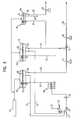
- the third embodiment of the invention shown in FIG. 3 The stock feed system differs from the first shown in FIG. 1 Embodiment in that the vent container 46 of the vent device 20 for the post-dilution liquid in its bottom area has only one outlet 52. At this outlet 52 is the supply line 54 is connected to the second mixing point 44 for post-dilution of the fiber suspension with deaerated post-dilution liquid to supply.
- the dilution liquid to be vented is supplied to the venting device 20 via a line 76.
- the dilution liquid is preferably also in this embodiment White water, so that line 76 the vent tank 46 can connect to the white water tank 22, for example. It is but also conceivable, a liquid other than post-dilution liquid to be used, such as sewage water or fresh water.
- venting device 78 provided one of the vent containers 33, 46 of the fiber suspension and post-dilution liquid separated Vent tank 80 has.
- This third vent 78 serves to vent an additional dilution liquid, those for a further dilution of the fiber suspension in the not shown Headbox is provided.
- This venting device 78 also can be of a known type.
- the additional dilution liquid becomes the vent tank 80 supplied via a line 82.
- the dilution liquid it can white water, sewage water or water of a different quality act with line 82 having a suitable water reservoir, not shown is connected, for example, in the case of white water the white water tank 22.
- the venting of the additional dilution liquid in the vent container 80 as well as the venting the pulp suspension and the venting of the post-dilution liquid by creating a vacuum in the vent tank 80.
- the same vacuum system 34 is used for vacuum generation, which is also used to deaerate the fiber suspension and the post-dilution liquid serves.
- the vent container 80 has an overflow arrangement 84 through the overflow of the at least partially deaerated dilution liquid Removable from the container 80 and via an overflow line 86 a dilution liquid reservoir, not shown, or for example the first mixing point 12 for predilution of the fiber suspension is feedable.
- venting container 80 88 There is also a spout in the bottom area of the venting container 80 88 is provided, to which a supply line 90 is connected.
- a pump 92 By means of a pump 92 is via the outlet 88 and the supply line 90 especially completely vented dilution liquid the vent container 80 and, for example, a third Dilution device for further dilution of the already diluted Fiber suspension can be fed into the headbox.
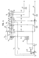
- the fourth embodiment of the invention shown in FIG. 4 differs from the third shown in FIG. 3 Embodiment in that the ventilation device 16 for the Fibrous suspension, the venting device 20 for the post-dilution liquid and vent 78 for the additional Dilution liquid a common vent tank 94th have, which by two partitions 68, 96 in a first compartment 70 for the pulp suspension, a second compartment 72 for the post-dilution liquid and a third compartment 98 for the additional dilution liquid is divided.
- Each of the three compartments 70, 72, 98 has the respective Feed lines 32, 48, 82, overflow arrangements already described above 36, 50, 84 and outlets 38, 52, 88.
- the common one Vent tank 94 of all three venting devices 16, 22, 78 is to generate the vacuum required for ventilation via a Vacuum line 100 connected to the common vacuum system 34.
Landscapes
- Engineering & Computer Science (AREA)
- Mechanical Engineering (AREA)
- Paper (AREA)
Abstract
Description
- erfordernisse. Dadurch wird die Flexibilität des erfindungsgemäßen Stoffzuführsystems weiter erhöht.
- Fig. 1
- ein erfindungsgemäßes Stoffzuführsystem gemäß einer ersten vorteilhaften Ausführungsform mit separaten Entlüftungsbehältern für Faserstoffsuspension und Nachverdünnungsflüssigkeit;
- Fig. 2
- ein erfindungsgemäßes Stoffzuführsystem gemäß einer zweiten vorteilhaften Ausführungsform mit einem gemeinsamen Entlüftungsbehälter für die Faserstoffsuspension und die Nachverdünnungsflüssigkeit;
- Fig. 3
- ein erfindungsgemäßes Stoffzuführsystem gemäß einer dritten vorteilhaften Ausführungsform mit jeweils separaten Entlüftungsbehältern für die Faserstoffsuspension, die Nachverdünnungsflüssigkeit und eine zusätzliche Verdünnungsflüssigkeit für eine weitere Verdünnung im Stoffauflauf; und
- Fig. 4
- ein erfindungsgemäßes Stoffzuführsystem gemäß einer vierten vorteilhaften Ausführungsform mit einem gemeinsamen Entlüftungsbehälter für die Faserstoffsuspension, die Nachverdünnungsflüssigkeit und die zusätzliche Verdünnungsflüssigkeit für die weitere Verdünnung im Stoffauflauf.
- 10
- Zuführleitung
- 12
- erste Mischstelle
- 14
- Leitung
- 16
- Entlüftungseinrichtung
- 18
- Leitung
- 20
- Entlüftungseinrichtung
- 22
- Siebwasserbehälter
- 24
- Versorgungsleitung
- 26
- erste Pumpe
- 28
- Leitung
- 30
- Reinigungsvorrichtung
- 32
- Leitung
- 33
- Entlüftungsbehälter
- 34
- Vakuumanlage
- 36
- Überlaufanordnung
- 38
- Auslauf
- 40
- Hauptstrangleitung
- 42
- zweite Pumpe
- 44
- zweite Mischstelle
- 46
- Entlüftungsbehälter
- 48
- Leitung
- 50
- Überlaufanordnung
- 52
- erster Auslauf
- 54
- Versorgungsleitung
- 56
- Stoffauflaufpumpe
- 58
- Hauptstrangleitung
- 60
- zweiter Auslauf
- 62
- Pumpe
- 64
- Versorgungsleitung
- 66
- Entlüftungsbehälter
- 68
- Trennwand
- 70
- erstes Fach
- 72
- zweites Fach
- 74
- Vakuumleitung
- 76
- Leitung
- 78
- Entlüftungseinrichtung
- 80
- Entlüftungsbehälter
- 82
- Leitung
- 84
- Überlaufanordnung
- 86
- Überlaufleitung
- 88
- Auslauf
- 90
- Versorgungsleitung
- 92
- Pumpe
- 94
- Entlüftungsbehälter
- 96
- Trennwand
- 98
- drittes Fach
- 100
- Vakuumleitung
Claims (14)
- Stoffzuführsystem zur Zuführung einer Faserstoffsuspension zu mindestens einem ein- oder mehrschichtigen Stoffauflauf, mit oder ohne weitere Verdünnungseinrichtung, einer Papier- oder Kartonmaschine mit mindestens einer ersten Verdünnungseinrichtung (12), insbesondere Vorverdünnungseinrichtung, und mindestens einer zweiten Verdünnungseinrichtung (44), insbesondere Nachverdünnungseinrichtung, zur Verdünnung der Faserstoffsuspension mit einer Verdünnungsflüssigkeit, insbesondere Wasser, und mindestens einer Einrichtung (16, 20, 78) zur, insbesondere weitgehend vollständigen, Entlüftung der Faserstoffsuspension und der Verdünnungsflüssigkeit,
dadurch gekennzeichnet, dass für die Entlüftung der bereits einmal verdünnten Faserstoffsuspension einerseits und der Verdünnungsflüssigkeit für die zweite Verdünnung andererseits separate Entlüftungseinrichtungen (16, 20) vorgesehen sind. - Stoffzuführsystem nach Anspruch 1,
dadurch gekennzeichnet, dass für die zweite Verdünnung mit entlüfteter Verdünnungsflüssigkeit eine definierte Mischstelle (44) vorgesehen ist, wobei die Mischstelle (44) insbesondere zwischen einer ersten, vorzugsweise mengengeregelten Pumpe (42) zum Eindüsen der entlüfteten Faserstoffsuspension in die Mischstelle (44) und einer zweiten Pumpe (56), insbesondere Stoffauflaufpumpe, zum Abziehen der verdünnten, insbesondere nachverdünnten, Faserstoffsuspension aus der Mischstelle (44) derart angeordnet ist, dass sich in Abhängigkeit von der Förderleistung der ersten und zweiten Pumpe (42, 56) automatisch die in die Mischstelle (44) einströmende Menge der Verdünnungsflüssigkeit für die zweite Verdünnung einstellt, wobei ferner die Fördermenge der zweiten Pumpe (56) bevorzugt größer als die Fördermenge der ersten Pumpe (42) ist und insbesondere 1500 bis 2000 Liter pro Minute beträgt. - Stoffzuführsystem nach Anspruch 2,
dadurch gekennzeichnet, dass die Mischstelle (44) in Strömungsrichtung der Faserstoffsuspension gesehen direkt vor der Stoffauflaufpumpe (56) angeordnet ist. - Stoffzuführsystem nach einem der vorherigen Ansprüche,
dadurch gekennzeichnet, dass zur Entlüftung der Faserstoffsuspension und der Verdünnungsflüssigkeit für die zweite Verdünnung getrennte Behälter (33, 46) vorgesehen sind oder dass zur Entlüftung der Faserstoffsuspension und der Verdünnungsflüssigkeit für die zweite Verdünnung ein gemeinsamer Behälter (66) vorgesehen ist, der entsprechend getrennte Fächer (70, 72) und separate Überläufe (36, 50) aufweist. - Stoffzuführsystem nach einem der vorherigen Ansprüche,
dadurch gekennzeichnet, dass für die Entlüftung der Faserstoffsuspension und der Verdünnungsflüssigkeit für die zweite Verdünnung eine gemeinsame Vakuumanlage (34) vorgesehen ist und/oder dass die Verdünnungsflüssigkeit für die zweite Verdünnung Siebwasser ist. - Stoffzuführsystem nach einem der vorherigen Ansprüche,
dadurch gekennzeichnet, dass bei einem Stoffauflauf mit weiterer Verdünnungseinrichtung eine Versorgungsleitung (64) zwischen der Entlüftungseinrichtung (20) für die Verdünnungsflüssigkeit für die zweite Verdünnung und der Verdünnungseinrichtung des Stoffauflaufs vorgesehen ist, über welche die Verdünnungseinrichtung des Stoffauflaufs mit entlüfteter Verdünnungsflüssigkeit versorgbar ist oder dass bei einem Stoffauflauf mit weiterer Verdünnungseinrichtung für die weitere Verdünnung der Faserstoffsuspension im Stoffauflauf eine von der Verdünnungsflüssigkeit für die erste und/ oder zweite Verdünnung verschiedene, zusätzliche Verdünnungsflüssigkeit vorgesehen ist, beispielsweise Siebwasser anderer Qualität oder Klärwasser, wobei bevorzugt eine weitere separate Entlüftungseinrichtung (78) für die Verdünnungsflüssigkeit des Stoffauflaufs vorgesehen ist. - Stoffzuführsystem nach Anspruch 6,
dadurch gekennzeichnet, dass zur Entlüftung der Verdünnungsflüssigkeit des Stoffauflaufs ein separater Behälter (80) vorgesehen ist oder dass zur Entlüftung der Verdünnungsflüssigkeit des Stoffauflaufs ein mit der Entlüftungseinrichtung für die Faserstoffsuspension und/oder mit der Entlüftungseinrichtung für die Verdünnungsflüssigkeit für die zweite Verdünnung gemeinsamer Behälter (94) vorgesehen ist, der entsprechend getrennte Fächer (70, 72, 98) und separate Überläufe (36, 50, 84) aufweist, wobei gegebenenfalls für die Entlüftung der Verdünnungsflüssigkeit des Stoffauflaufs und der Faserstoffsuspension und/oder der Verdünnungsflüssigkeit für die zweite Verdünnung bevorzugt eine gemeinsame Vakuumanlage (34) vorgesehen ist. - Stoffzuführsystem nach einem der vorherigen Ansprüche,
dadurch gekennzeichnet, dass insbesondere zwischen der ersten Verdünnungseinrichtung (12) und der Entlüftungseinrichtung (16) für die Faserstoffsuspension mindestens eine Reinigungsvorrichtung (30) vorgesehen ist. - Verfahren zum Zuführen einer Faserstoffsuspension zu mindestens einem ein- oder mehrschichtigen Stoffauflauf, mit oder ohne weitere Verdünnungseinrichtung, einer Papier- oder Kartonmaschine, bei welchem die Faserstoffsuspension mindestens einer ersten Verdünnung, insbesondere Vorverdünnung, und mindestens einer zweiten Verdünnung, insbesondere Nachverdünnung, mit einer Verdünnungsflüssigkeit, insbesondere Wasser, unterzogen wird und bei welchem die Faserstoffsuspension und die Verdünnungsflüssigkeit, insbesondere weitgehend vollständig, entlüftet werden,
dadurch gekennzeichnet, dass die bereits einmal verdünnte Faserstoffsuspension einerseits und die Verdünnungsflüssigkeit für die zweite Verdünnung andererseits separat entlüftet werden. - Verfahren nach Anspruch 9,
dadurch gekennzeichnet, dass die bereits einmal verdünnte und entlüftete Faserstoffsuspension in einer Mischstelle (44) definiert mit der entlüfteten Verdünnungsflüssigkeit für die zweite Verdünnung vermischt wird, wobei die Faserstoffsuspension bevorzugt, insbesondere mengengeregelt, in die Mischstelle (44) eingedüst und, ebenfalls insbesondere mengengeregelt, aus der Mischstelle (44) abgezogen wird, so dass sich in Abhängigkeit von der eingedüsten Menge und der abgezogenen Menge automatisch die in die Mischstelle einströmende Menge der Verdünnungsflüssigkeit einstellt. - Verfahren nach Anspruch 9 oder 10,
dadurch gekennzeichnet, dass die Faserstoffsuspension und die Verdünnungsflüssigkeit für die zweite Verdünnung in getrennten Behältern (33, 46) entlüftet werden oder dass die Faserstoffsuspension und die Verdünnungsflüssigkeit für die zweite Verdünnung in einem gemeinsamen Behälter (66) mit entsprechend getrennten Fächern (70, 72) und separaten Überläufen (36, 50) entlüftet werden, wobei bevorzugt die Faserstoffsuspension im Stoffauflauf durch Vermischung mit derselben Verdünnungsflüssigkeit wie für die zweite Verdünnung weiter verdünnt wird. - Verfahren nach einem der Ansprüche 9 bis 11,
dadurch gekennzeichnet, dass die Faserstoffsuspension im Stoffauflauf durch eine von der Verdünnungsflüssigkeit für die erste und/oder zweite Verdünnung verschiedene, zusätzliche Verdünnungsflüssigkeit, beispielsweise Siebwasser anderer Qualität oder Klärwasser, weiter verdünnt wird, wobei die Verdünnungsflüssigkeit für den Stoffauflauf bevorzugt separat entlüftet wird. - Verfahren nach Anspruch 12,
dadurch gekennzeichnet, dass die Verdünnungsflüssigkeit für den Stoffauflauf in einem separaten Behälter (80) entlüftet wird oder dass die Verdünnungsflüssigkeit für den Stoffauflauf mit der Faserstoffsuspension und/oder mit der Verdünnungsflüssigkeit für die zweite Verdünnung in einem gemeinsamen Behälter (94) entlüftet wird, der entsprechend getrennte Fächer (70, 72, 98) und separate Überläufe (36, 50, 84) aufweist. - Verfahren nach einem der Ansprüche 9 bis 13,
dadurch gekennzeichnet, dass die Faserstoffsuspension und/oder die Verdünnungsflüssigkeit für die zweite Verdünnung und/oder die Verdünnungsflüssigkeit für den Stoffauflauf durch eine gemeinsame Vakuumanlage (34) entlüftet werden und/oder dass die Faserstoffsuspension insbesondere zwischen der ersten Verdünnung und der Entlüftung mindestens einmal gereinigt wird.
Applications Claiming Priority (2)
| Application Number | Priority Date | Filing Date | Title |
|---|---|---|---|
| DE10250865 | 2002-10-31 | ||
| DE10250865A DE10250865B3 (de) | 2002-10-31 | 2002-10-31 | System und Verfahren zur Zuführung einer Faserstoffsuspension zu einem Stoffauflauf |
Publications (2)
| Publication Number | Publication Date |
|---|---|
| EP1416084A1 true EP1416084A1 (de) | 2004-05-06 |
| EP1416084B1 EP1416084B1 (de) | 2007-03-07 |
Family
ID=32087315
Family Applications (1)
| Application Number | Title | Priority Date | Filing Date |
|---|---|---|---|
| EP03022309A Expired - Lifetime EP1416084B1 (de) | 2002-10-31 | 2003-10-02 | System und Verfahren zur Zuführung einer Faserstoffsuspension in einem Stoffauflauf |
Country Status (4)
| Country | Link |
|---|---|
| EP (1) | EP1416084B1 (de) |
| CN (1) | CN1499009A (de) |
| AT (1) | ATE356249T1 (de) |
| DE (2) | DE10250865B3 (de) |
Cited By (2)
| Publication number | Priority date | Publication date | Assignee | Title |
|---|---|---|---|---|
| WO2005005716A1 (en) * | 2003-07-09 | 2005-01-20 | Sulzer Pumpen Ag | Method and arrangement for treating pulp |
| EP2988843B1 (de) * | 2013-04-26 | 2018-06-13 | Voith Patent GmbH | Suspensionsentgasung |
Families Citing this family (2)
| Publication number | Priority date | Publication date | Assignee | Title |
|---|---|---|---|---|
| DE102004042341B4 (de) * | 2004-09-01 | 2007-04-12 | Voith Patent Gmbh | System und Verfahren zur Zuführung einer Faserstoffsuspension zu einem Stoffauflauf |
| CN107913606B (zh) * | 2017-10-24 | 2020-07-28 | 浙江福斯特新材料研究院有限公司 | 一种半透膜支撑材料及其制备方法 |
Citations (2)
| Publication number | Priority date | Publication date | Assignee | Title |
|---|---|---|---|---|
| US3432036A (en) * | 1964-12-09 | 1969-03-11 | Clark & Vicario Corp | Conditioning papermaking stock |
| DE10050109A1 (de) * | 2000-10-09 | 2002-04-11 | Voith Paper Patent Gmbh | Verfahren und Mischvorrichtung zur Erzeugung einer fertigen Faserstoffsuspension |
Family Cites Families (3)
| Publication number | Priority date | Publication date | Assignee | Title |
|---|---|---|---|---|
| DE4106140C2 (de) * | 1991-02-27 | 1994-11-24 | Escher Wyss Gmbh | Vorrichtung und deren Anwendung zur Entlüftung einer Papierstoffsuspension |
| FI103677B (fi) * | 1998-06-10 | 1999-08-13 | Valmet Corp | Menetelmä osamassan annostelusäiliön pinnankorkeuden ja sakeuden säätä miseksi |
| DE19947905A1 (de) * | 1999-10-06 | 2001-04-12 | Voith Paper Patent Gmbh | Vorrichtung zum Engasen von Faserstoffsuspensionen |
-
2002
- 2002-10-31 DE DE10250865A patent/DE10250865B3/de not_active Expired - Fee Related
-
2003
- 2003-10-02 EP EP03022309A patent/EP1416084B1/de not_active Expired - Lifetime
- 2003-10-02 AT AT03022309T patent/ATE356249T1/de active
- 2003-10-02 DE DE50306732T patent/DE50306732D1/de not_active Expired - Lifetime
- 2003-10-30 CN CNA2003101029494A patent/CN1499009A/zh active Pending
Patent Citations (2)
| Publication number | Priority date | Publication date | Assignee | Title |
|---|---|---|---|---|
| US3432036A (en) * | 1964-12-09 | 1969-03-11 | Clark & Vicario Corp | Conditioning papermaking stock |
| DE10050109A1 (de) * | 2000-10-09 | 2002-04-11 | Voith Paper Patent Gmbh | Verfahren und Mischvorrichtung zur Erzeugung einer fertigen Faserstoffsuspension |
Cited By (2)
| Publication number | Priority date | Publication date | Assignee | Title |
|---|---|---|---|---|
| WO2005005716A1 (en) * | 2003-07-09 | 2005-01-20 | Sulzer Pumpen Ag | Method and arrangement for treating pulp |
| EP2988843B1 (de) * | 2013-04-26 | 2018-06-13 | Voith Patent GmbH | Suspensionsentgasung |
Also Published As
| Publication number | Publication date |
|---|---|
| DE50306732D1 (de) | 2007-04-19 |
| EP1416084B1 (de) | 2007-03-07 |
| CN1499009A (zh) | 2004-05-26 |
| ATE356249T1 (de) | 2007-03-15 |
| DE10250865B3 (de) | 2004-05-13 |
Similar Documents
| Publication | Publication Date | Title |
|---|---|---|
| DE4019593C2 (de) | Stoffauflauf für Papiermaschinen | |
| DE69717656T2 (de) | Faserbreizuführsystem für einen mehrlagen stoffauflaufkasten sowie verfahren zum betreiben eines solchen stoffauflaufkasten | |
| DE69919175T2 (de) | Verfahren für den kurzen umlauf in einer papier- oder pappenmaschine | |
| DE2317402B2 (de) | Verfahren zur Herstellung einer nicht-gewebten Fasermatte und Vorrichtung zur Durchführung des Verfahrens | |
| DE4416909A1 (de) | Verfahren zur lokalen Zumischung von Fluid in einen Stoffauflauf für eine Papiermaschine sowie Stoffauflauf zu seiner Durchführung | |
| WO2009021805A1 (de) | Konstantteil für eine papiermaschine | |
| DE69114295T2 (de) | Verfahren und vorrichtung zur stabilisierung und vereinfachung eines stoffverteilers für eine papiermaschine. | |
| EP0733735A2 (de) | Nasspartie einer Papiermaschiene | |
| EP1645684B1 (de) | Verfahren und Vorrichtung zur Regelung des Flächengewichtsquerprofils einer Faserstoffbahn | |
| EP1416084B1 (de) | System und Verfahren zur Zuführung einer Faserstoffsuspension in einem Stoffauflauf | |
| DE69922549T2 (de) | Herstellung von mehrschichtigen bahnen aus einem einzigem grundfaserstoff | |
| DE19859770A1 (de) | Verfahren und Vorrichtung zum Mischen von Sroffsuspension | |
| DD296722A5 (de) | Verfahren und vorrichtung zur erzeugung von zellulosebrei mit verbeserter qualitaet | |
| EP2598690B1 (de) | Konstantteil einer maschine zur herstellung einer faserstoffbahn | |
| DE19520916A1 (de) | Einrichtung zur Versorgung von Hämodialysegeräten mit Dialysierflüssigkeit | |
| DE102004042341B4 (de) | System und Verfahren zur Zuführung einer Faserstoffsuspension zu einem Stoffauflauf | |
| DE19845536C2 (de) | Verfahren zur Entfernung von Störstoffen aus einer wässrigen papierfaserhaltigen Suspension | |
| EP1731662B1 (de) | Verfahren und Vorrichtung zum Wiederaufbereiten von Altpapier | |
| DE19952129A1 (de) | Verfahren und Vorrichtung zur Entgasung einer Papierstoffsuspension | |
| DE60012047T2 (de) | Verfahren zur regelung des betriebs eines näherungssystems in einer papiermaschine oder dergleichen | |
| AT397213B (de) | Verfahren und anlage zur rückgewinnung von feststoffen | |
| AT522849B1 (de) | Verfahren und system zum sieben einer beschichtungsmischung in einer faserbahnmaschine | |
| DE69915089T2 (de) | Verfahren und vorrichtung zur vorbehandlung von papierfaserstoff | |
| EP0971069B1 (de) | Misch- und Rezirkulationskreislauf | |
| WO2009021803A1 (de) | Konstantteil für eine papiermaschine |
Legal Events
| Date | Code | Title | Description |
|---|---|---|---|
| PUAI | Public reference made under article 153(3) epc to a published international application that has entered the european phase |
Free format text: ORIGINAL CODE: 0009012 |
|
| AK | Designated contracting states |
Kind code of ref document: A1 Designated state(s): AT BE BG CH CY CZ DE DK EE ES FI FR GB GR HU IE IT LI LU MC NL PT RO SE SI SK TR |
|
| AX | Request for extension of the european patent |
Extension state: AL LT LV MK |
|
| 17P | Request for examination filed |
Effective date: 20040603 |
|
| AKX | Designation fees paid |
Designated state(s): AT BE BG CH CY CZ DE DK EE ES FI FR GB GR HU IE IT LI LU MC NL PT RO SE SI SK TR |
|
| RAP1 | Party data changed (applicant data changed or rights of an application transferred) |
Owner name: VOITH PATENT GMBH |
|
| GRAP | Despatch of communication of intention to grant a patent |
Free format text: ORIGINAL CODE: EPIDOSNIGR1 |
|
| GRAS | Grant fee paid |
Free format text: ORIGINAL CODE: EPIDOSNIGR3 |
|
| GRAA | (expected) grant |
Free format text: ORIGINAL CODE: 0009210 |
|
| AK | Designated contracting states |
Kind code of ref document: B1 Designated state(s): AT BE BG CH CY CZ DE DK EE ES FI FR GB GR HU IE IT LI LU MC NL PT RO SE SI SK TR |
|
| PG25 | Lapsed in a contracting state [announced via postgrant information from national office to epo] |
Ref country code: SI Free format text: LAPSE BECAUSE OF FAILURE TO SUBMIT A TRANSLATION OF THE DESCRIPTION OR TO PAY THE FEE WITHIN THE PRESCRIBED TIME-LIMIT Effective date: 20070307 Ref country code: NL Free format text: LAPSE BECAUSE OF FAILURE TO SUBMIT A TRANSLATION OF THE DESCRIPTION OR TO PAY THE FEE WITHIN THE PRESCRIBED TIME-LIMIT Effective date: 20070307 Ref country code: IE Free format text: LAPSE BECAUSE OF FAILURE TO SUBMIT A TRANSLATION OF THE DESCRIPTION OR TO PAY THE FEE WITHIN THE PRESCRIBED TIME-LIMIT Effective date: 20070307 |
|
| REG | Reference to a national code |
Ref country code: GB Ref legal event code: FG4D Free format text: NOT ENGLISH |
|
| REG | Reference to a national code |
Ref country code: CH Ref legal event code: EP |
|
| REF | Corresponds to: |
Ref document number: 50306732 Country of ref document: DE Date of ref document: 20070419 Kind code of ref document: P |
|
| REG | Reference to a national code |
Ref country code: IE Ref legal event code: FG4D Free format text: LANGUAGE OF EP DOCUMENT: GERMAN |
|
| GBT | Gb: translation of ep patent filed (gb section 77(6)(a)/1977) |
Effective date: 20070517 |
|
| PG25 | Lapsed in a contracting state [announced via postgrant information from national office to epo] |
Ref country code: ES Free format text: LAPSE BECAUSE OF FAILURE TO SUBMIT A TRANSLATION OF THE DESCRIPTION OR TO PAY THE FEE WITHIN THE PRESCRIBED TIME-LIMIT Effective date: 20070618 |
|
| REG | Reference to a national code |
Ref country code: SE Ref legal event code: TRGR |
|
| PG25 | Lapsed in a contracting state [announced via postgrant information from national office to epo] |
Ref country code: PT Free format text: LAPSE BECAUSE OF FAILURE TO SUBMIT A TRANSLATION OF THE DESCRIPTION OR TO PAY THE FEE WITHIN THE PRESCRIBED TIME-LIMIT Effective date: 20070807 |
|
| NLV1 | Nl: lapsed or annulled due to failure to fulfill the requirements of art. 29p and 29m of the patents act | ||
| REG | Reference to a national code |
Ref country code: IE Ref legal event code: FD4D |
|
| PG25 | Lapsed in a contracting state [announced via postgrant information from national office to epo] |
Ref country code: SK Free format text: LAPSE BECAUSE OF FAILURE TO SUBMIT A TRANSLATION OF THE DESCRIPTION OR TO PAY THE FEE WITHIN THE PRESCRIBED TIME-LIMIT Effective date: 20070307 |
|
| PG25 | Lapsed in a contracting state [announced via postgrant information from national office to epo] |
Ref country code: RO Free format text: LAPSE BECAUSE OF FAILURE TO SUBMIT A TRANSLATION OF THE DESCRIPTION OR TO PAY THE FEE WITHIN THE PRESCRIBED TIME-LIMIT Effective date: 20070307 Ref country code: CZ Free format text: LAPSE BECAUSE OF FAILURE TO SUBMIT A TRANSLATION OF THE DESCRIPTION OR TO PAY THE FEE WITHIN THE PRESCRIBED TIME-LIMIT Effective date: 20070307 |
|
| PLBE | No opposition filed within time limit |
Free format text: ORIGINAL CODE: 0009261 |
|
| STAA | Information on the status of an ep patent application or granted ep patent |
Free format text: STATUS: NO OPPOSITION FILED WITHIN TIME LIMIT |
|
| PG25 | Lapsed in a contracting state [announced via postgrant information from national office to epo] |
Ref country code: DK Free format text: LAPSE BECAUSE OF FAILURE TO SUBMIT A TRANSLATION OF THE DESCRIPTION OR TO PAY THE FEE WITHIN THE PRESCRIBED TIME-LIMIT Effective date: 20070307 |
|
| 26N | No opposition filed |
Effective date: 20071210 |
|
| BERE | Be: lapsed |
Owner name: VOITH PATENT G.M.B.H. Effective date: 20071031 |
|
| PG25 | Lapsed in a contracting state [announced via postgrant information from national office to epo] |
Ref country code: GR Free format text: LAPSE BECAUSE OF FAILURE TO SUBMIT A TRANSLATION OF THE DESCRIPTION OR TO PAY THE FEE WITHIN THE PRESCRIBED TIME-LIMIT Effective date: 20070608 |
|
| PG25 | Lapsed in a contracting state [announced via postgrant information from national office to epo] |
Ref country code: MC Free format text: LAPSE BECAUSE OF NON-PAYMENT OF DUE FEES Effective date: 20071031 |
|
| PG25 | Lapsed in a contracting state [announced via postgrant information from national office to epo] |
Ref country code: BE Free format text: LAPSE BECAUSE OF NON-PAYMENT OF DUE FEES Effective date: 20071031 |
|
| PG25 | Lapsed in a contracting state [announced via postgrant information from national office to epo] |
Ref country code: EE Free format text: LAPSE BECAUSE OF FAILURE TO SUBMIT A TRANSLATION OF THE DESCRIPTION OR TO PAY THE FEE WITHIN THE PRESCRIBED TIME-LIMIT Effective date: 20070307 |
|
| PG25 | Lapsed in a contracting state [announced via postgrant information from national office to epo] |
Ref country code: CY Free format text: LAPSE BECAUSE OF FAILURE TO SUBMIT A TRANSLATION OF THE DESCRIPTION OR TO PAY THE FEE WITHIN THE PRESCRIBED TIME-LIMIT Effective date: 20070307 |
|
| PG25 | Lapsed in a contracting state [announced via postgrant information from national office to epo] |
Ref country code: BG Free format text: LAPSE BECAUSE OF FAILURE TO SUBMIT A TRANSLATION OF THE DESCRIPTION OR TO PAY THE FEE WITHIN THE PRESCRIBED TIME-LIMIT Effective date: 20070607 Ref country code: LU Free format text: LAPSE BECAUSE OF NON-PAYMENT OF DUE FEES Effective date: 20071002 |
|
| PG25 | Lapsed in a contracting state [announced via postgrant information from national office to epo] |
Ref country code: TR Free format text: LAPSE BECAUSE OF FAILURE TO SUBMIT A TRANSLATION OF THE DESCRIPTION OR TO PAY THE FEE WITHIN THE PRESCRIBED TIME-LIMIT Effective date: 20070307 Ref country code: HU Free format text: LAPSE BECAUSE OF FAILURE TO SUBMIT A TRANSLATION OF THE DESCRIPTION OR TO PAY THE FEE WITHIN THE PRESCRIBED TIME-LIMIT Effective date: 20070908 |
|
| PGFP | Annual fee paid to national office [announced via postgrant information from national office to epo] |
Ref country code: AT Payment date: 20101014 Year of fee payment: 8 |
|
| PGFP | Annual fee paid to national office [announced via postgrant information from national office to epo] |
Ref country code: DE Payment date: 20101022 Year of fee payment: 8 |
|
| PGFP | Annual fee paid to national office [announced via postgrant information from national office to epo] |
Ref country code: GB Payment date: 20101021 Year of fee payment: 8 Ref country code: IT Payment date: 20101025 Year of fee payment: 8 |
|
| PGFP | Annual fee paid to national office [announced via postgrant information from national office to epo] |
Ref country code: FR Payment date: 20111103 Year of fee payment: 9 Ref country code: FI Payment date: 20111013 Year of fee payment: 9 Ref country code: CH Payment date: 20111024 Year of fee payment: 9 Ref country code: SE Payment date: 20111021 Year of fee payment: 9 |
|
| REG | Reference to a national code |
Ref country code: CH Ref legal event code: PL |
|
| REG | Reference to a national code |
Ref country code: AT Ref legal event code: MM01 Ref document number: 356249 Country of ref document: AT Kind code of ref document: T Effective date: 20121002 |
|
| GBPC | Gb: european patent ceased through non-payment of renewal fee |
Effective date: 20121002 |
|
| REG | Reference to a national code |
Ref country code: FR Ref legal event code: ST Effective date: 20130628 |
|
| PG25 | Lapsed in a contracting state [announced via postgrant information from national office to epo] |
Ref country code: SE Free format text: LAPSE BECAUSE OF NON-PAYMENT OF DUE FEES Effective date: 20121003 Ref country code: AT Free format text: LAPSE BECAUSE OF NON-PAYMENT OF DUE FEES Effective date: 20121002 Ref country code: GB Free format text: LAPSE BECAUSE OF NON-PAYMENT OF DUE FEES Effective date: 20121002 Ref country code: LI Free format text: LAPSE BECAUSE OF NON-PAYMENT OF DUE FEES Effective date: 20121031 Ref country code: CH Free format text: LAPSE BECAUSE OF NON-PAYMENT OF DUE FEES Effective date: 20121031 Ref country code: DE Free format text: LAPSE BECAUSE OF NON-PAYMENT OF DUE FEES Effective date: 20130501 |
|
| REG | Reference to a national code |
Ref country code: DE Ref legal event code: R119 Ref document number: 50306732 Country of ref document: DE Effective date: 20130501 |
|
| PG25 | Lapsed in a contracting state [announced via postgrant information from national office to epo] |
Ref country code: IT Free format text: LAPSE BECAUSE OF NON-PAYMENT OF DUE FEES Effective date: 20121002 Ref country code: FI Free format text: LAPSE BECAUSE OF NON-PAYMENT OF DUE FEES Effective date: 20121002 Ref country code: FR Free format text: LAPSE BECAUSE OF NON-PAYMENT OF DUE FEES Effective date: 20121031 |