EP1415749A2 - Klappen für eine Schweissvorrichtung - Google Patents
Klappen für eine Schweissvorrichtung Download PDFInfo
- Publication number
- EP1415749A2 EP1415749A2 EP03019709A EP03019709A EP1415749A2 EP 1415749 A2 EP1415749 A2 EP 1415749A2 EP 03019709 A EP03019709 A EP 03019709A EP 03019709 A EP03019709 A EP 03019709A EP 1415749 A2 EP1415749 A2 EP 1415749A2
- Authority
- EP
- European Patent Office
- Prior art keywords
- louvers
- louver
- edge
- assembly
- welding apparatus
- Prior art date
- Legal status (The legal status is an assumption and is not a legal conclusion. Google has not performed a legal analysis and makes no representation as to the accuracy of the status listed.)
- Granted
Links
Images


Classifications
-
- H—ELECTRICITY
- H05—ELECTRIC TECHNIQUES NOT OTHERWISE PROVIDED FOR
- H05K—PRINTED CIRCUITS; CASINGS OR CONSTRUCTIONAL DETAILS OF ELECTRIC APPARATUS; MANUFACTURE OF ASSEMBLAGES OF ELECTRICAL COMPONENTS
- H05K5/00—Casings, cabinets or drawers for electric apparatus
- H05K5/02—Details
- H05K5/0213—Venting apertures; Constructional details thereof
-
- B—PERFORMING OPERATIONS; TRANSPORTING
- B23—MACHINE TOOLS; METAL-WORKING NOT OTHERWISE PROVIDED FOR
- B23K—SOLDERING OR UNSOLDERING; WELDING; CLADDING OR PLATING BY SOLDERING OR WELDING; CUTTING BY APPLYING HEAT LOCALLY, e.g. FLAME CUTTING; WORKING BY LASER BEAM
- B23K9/00—Arc welding or cutting
- B23K9/10—Other electric circuits therefor; Protective circuits; Remote controls
- B23K9/1006—Power supply
-
- H—ELECTRICITY
- H05—ELECTRIC TECHNIQUES NOT OTHERWISE PROVIDED FOR
- H05K—PRINTED CIRCUITS; CASINGS OR CONSTRUCTIONAL DETAILS OF ELECTRIC APPARATUS; MANUFACTURE OF ASSEMBLAGES OF ELECTRICAL COMPONENTS
- H05K5/00—Casings, cabinets or drawers for electric apparatus
- H05K5/02—Details
- H05K5/0213—Venting apertures; Constructional details thereof
- H05K5/0214—Venting apertures; Constructional details thereof with means preventing penetration of rain water or dust
-
- H—ELECTRICITY
- H05—ELECTRIC TECHNIQUES NOT OTHERWISE PROVIDED FOR
- H05K—PRINTED CIRCUITS; CASINGS OR CONSTRUCTIONAL DETAILS OF ELECTRIC APPARATUS; MANUFACTURE OF ASSEMBLAGES OF ELECTRICAL COMPONENTS
- H05K7/00—Constructional details common to different types of electric apparatus
- H05K7/20—Modifications to facilitate cooling, ventilating, or heating
- H05K7/20009—Modifications to facilitate cooling, ventilating, or heating using a gaseous coolant in electronic enclosures
- H05K7/20136—Forced ventilation, e.g. by fans
- H05K7/20181—Filters; Louvers
-
- Y—GENERAL TAGGING OF NEW TECHNOLOGICAL DEVELOPMENTS; GENERAL TAGGING OF CROSS-SECTIONAL TECHNOLOGIES SPANNING OVER SEVERAL SECTIONS OF THE IPC; TECHNICAL SUBJECTS COVERED BY FORMER USPC CROSS-REFERENCE ART COLLECTIONS [XRACs] AND DIGESTS
- Y10—TECHNICAL SUBJECTS COVERED BY FORMER USPC
- Y10S—TECHNICAL SUBJECTS COVERED BY FORMER USPC CROSS-REFERENCE ART COLLECTIONS [XRACs] AND DIGESTS
- Y10S454/00—Ventilation
- Y10S454/905—Black out means
Definitions
- the present invention relates generally to a welding apparatus and, more particularly, a welding apparatus having a specially configured louver assembly for a vent opening in the welding apparatus.
- the welding apparatus normally has one or more vent openings in the enclosure to allow the ambient air to enter into the enclosure to provide that cooling function.
- the vent opening is required, in order to attain a certain rating, to be constructed so as to prevent a straight cylindrical probe having a diameter of about 2.5 mm from penetrating the vent opening to reach the internal area of the enclosure.
- vent openings of welding apparatus have conventional louvers across the vent opening
- the conventional louvers also then have a wire mesh screen proximate to the louvers in order to provide a means of preventing that aforedescribed probe from passing through the louvers and into the interior of the enclosure.
- louver configuration that could be usable within the vent opening of a welding apparatus that would prevent the standard probe from passing through the louver configuration while allowing sufficient ambient air to enter the enclosure to cool the components within the enclosure.
- the present invention is directed to an improved louver configuration for a vent opening of an assembled apparatus, preferable a welding apparatus.
- the welding apparatus comprises an enclosure that contains the various components needed to provide a selectively variable current to carry out the welding process.
- the enclosure has a vent opening therein to allow ambient air to circulate though the enclosure.
- the specially configured louvers are provided in the rear panel to prevent intrusion to an area in the enclosure where the primary power is near. Accordingly, there is formed a plurality of louvers in the rear panel that span the vent opening, are parallel to each other, and have the same configuration. The louvers are formed such that adjacent louvers are closely spaced apart and basically have the same side profile so that each of the louvers is aligned with each other louver.
- each louver is specially constructed and has a front portion that is generally planar and has a front edge that faces outwardly with respect to the interior of the welding apparatus. There is also a rear portion that is also planar and which extends toward the interior of the enclosure ending in a rear edge facing inwardly toward the interior of the welding apparatus and is preferably oriented in a plane that is generally horizontal. The rear portion and the front portion intersect at an angle to form an intermediate edge.
- the front edge of the louvers extends outwardly with respect to the interior of the enclosure and therefore repels liquids that hit the front a rea of the enclosure since the front portion of each louver is angled downwardly in the direction away from the interior of the enclosure. As such, the liquid runs downwardly such that the liquid does not enter into the interior of the enclosure.
- the rear portions are oriented so as to be generally horizontal so that the air entering through the vent opening is less turbulent as it enters the interior of the enclosure and therefore the cooling effect is more efficient.
- louvers In all, with the present configuration of louvers, the spacing between adjacent louvers not only enhances the flow of air, but reduces the problem of dirt and debris clogging the openings between the louvers.
- the welding apparatus 10 comprises an enclosure 12 that is of sheet metal construction, preferable of aluminum, and having a front panel 14 and a rear panel 16. Both the front and rear panels 14, 16 are preferably constructed of a molded plastic material.
- the front panel 14 has a central control section and which includes the various controls for the welding functions and can include female connectors 15 that are used to connect the welding cables.
- a control knob 18 is provided in order to control the current to the welding electrodes and a selector button 20 is provided to enable the welding apparatus to be switched between TIG and stick operations. There may also be a series of LED's 22 to provide an indication of status of the welding apparatus and to provide information as to its operation.
- a remote connector plug 24 is also used for the operation of remote controls such as a foot operated switch for the welding apparatus 10.
- a base 26 is located underneath the enclosure 12 and can also be of molded plastic construction and, as can be seen, the base 26 can a ctually be elevated with respect to the floor such that the welding apparatus 10 contacts the floor through the front and rear panels 14, 16.
- vent opening 28 formed in the front panel 14 of the enclosure 12 and a similar vent opening 30 formed in the rear panel 16 of the enclosure 12.
- a plurality of louvers 32 are formed within each of the vent openings 28, 30, in order to allow ambient air to circulate between the vent openings 28, 30 to cool the various components contained within the enclosure 12.
- a forced air circulation device such as a fan (not shown).
- the louvers 32 can be similar in both the front panel 14 and rear panel 16, and, therefore, the construction and configuration of the louvers 32 in the rear panel 16 will be described for purposes of explaining the present invention.
- the rear panel 16 conceals the primary contacts and leads, it is not necessarily necessary to include louvers in accordance with the present invention in both panels 14, 16.
- the rear panel 16 requires the specially constructed louvers. However, it may be found to be more economical to construct both louvers the same.
- Fig, 2 taken along with Fig. 1, there is shown a cross sectional view of the rear panel 16 and illustrating the louvers 32 of the invention.
- the louvers 32 are formed in the rear panel 16 such that they are in a side by side parallel relationship, that is, the side profile of each louver 32 is the same as the side profile of an adjacent louver 32 and the louvers 32 are spaced apart a distance "d" as shown in Fig. 2.
- Each louver 32 has a front portion 34 and a rear portion 36.
- the front portion 34 has a front edge 38 that faces away from the interior of the enclosure 10 and the rear portion 36 has a rear edge 40 that faces toward the interior of the enclosure 12.
- the front and rear portions 34, 36 meet at an angle to each other to form an intermediate edge 42 that is displaced or offset a predetermined distance away from a straight line drawn between the front edge 38 and the rear edge 40.
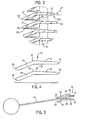
- Fig. 3 along with Figs. 1 and 2, there is shown an enlarged cross sectional view of the louvers 32 of the present invention illustrating the configuration and geometry of the front portion 34 and the rear portion 36.
- the rear portion 36 of a louver 32 is preferably in a generally horizontal plane, and the front portion is angled downwardly with respect to the horizontal plane. This arrangement allows air to enter the enclosure more linearly, thereby creating less turbulence and providing more efficient cooling.
- the louvers are tapered front to back from the front edge 38 to the back edge 40.
- the aforementioned arrangement prevents intrusion of articles of a certain size.
- the orientation of the louver arrangement can be described by a line 37 extending along the front portion 34 from the front edge 38 to the intermediate edge 42 of a first louver 32A that continues to extend to and intersect with the rear edge 40 of a rear portion 36 of a louver 32B immediate above the first louver 32A.
- any moisture that lands or collects on the louvers 32 will drain downwardly and away for the interior of the enclosure 12.
- the rear portion 36 oriented in a generally horizontal plane, the air that passes through the louvers 32 inwardly to the interior of the enclosure 12 enters the interior linearly, thereby having less turbulence and thus creating more efficient cooling.
- FIG. 4 there is shown a side cross-sectional view of two adjacent louvers 32 and illustrating the configuration and orientation of each louver 32, which is typical of the louvers 32 of the enclosure 12 (Fig. 1).
- the side profile of the louvers 32 can be seen and that side profile is the same for adjacent louvers 32.
- the intermediate edge 42 can be seen to be offset or displaced outwardly from a straight line passing between the front edge 38 and the rear edge 40.
- the preferred orientation is with the rear portion 36 in a generally horizontal plane with the front portion 34 angled downwardly with respect to a horizontal plane in the direction facing outwardly from the interior of the enclosure 12 (Fig. 1).
- Fig. 5 there is shown a schematic view of adjacent louvers 32 of the present invention and with a probe 44 that is in a position to attempt to pass the probe 44 between adjacent louvers 32.
- the probe 44 is a standard designated probe that is used for a safety rating test for welding apparatus.
- the diameter of the cylindrical probe is 2.5 mm.
- the test applies to any adjacent louvers 32.
- the louvers 32 in Fig. 5 will be referred to as an upper louver 46 and a lower louver 48.
- the standards basically require that the probe 44 be prevented from passing though the louvers 32 so that an end of the probe 44 cannot reach the interior of the welding apparatus.
- the louvers 32 are configured and spaced apart such that an attempt to introduce the probe 44 through the space between the upper and lower louvers 46, 48 results in the probe 44 encountering the front edge 38 of the upper louver 46 and the intermediate edge 42 of the lower louver 48 such that the path or angle of the probe 44 is determined by those edges. Further introduction of the probe 44 results in the probe 44 encountering the rear edge 40 of the upper louver 46. The probe 44 is therefore prevented by that rear edge 40 from passing further into the interior of the enclosure 12 (Fig. 1) and thereby satisfies the rating test.
- louvers 32 Accordingly, by the configuration and spacing apart of the louvers 32, considerable air can pass through the space between the louvers 32 into and out of the enclosure for cooling. However, the safety rating can still be maintained with the present louvers since the probe 44 cannot pass through adjacent louvers 32.
- the set of louvers 32 are connected to one another through a single center post 50 and is constructed to form a one-piece assembly 52 wherein a lower half 54 of the assembly 52 includes the series of louvers 32 that terminate at a midpoint 56 of the assembly 52.
- An uppermost louver 58 is formed without a horizontal rear portion, and is constructed such that the front portion 34 of the uppermost louver 58 is connected to a vertically extending member 60 that forms an upper half 62 of the one-piece assembly 52 to form the rear panel 16 of the welder 10.
- the vertically extending member 60 of the uppermost louver 58 includes mounting bosses 64 extending therefrom for attachment of the one-piece assembly 52 to the enclosure 12 of the welder 10.
- welding devices not only includes welders, but also includes any system that requires high power outputs, such as heating and cutting systems. Therefore, the present invention is equivalently applicable with any device requiring high power output, including welders, plasma cutters, induction heaters, and the like.
- Reference to welding power, welding-type power, or welders generally, includes welding, cutting, or heating power.
- Description of a welding apparatus illustrates just one embodiment in which the present invention may be implemented. The present invention is equivalently applicable with many high power systems, such as cutting and induction heating systems, or any similar systems.
Landscapes
- Engineering & Computer Science (AREA)
- Microelectronics & Electronic Packaging (AREA)
- Physics & Mathematics (AREA)
- Plasma & Fusion (AREA)
- Mechanical Engineering (AREA)
- Thermal Sciences (AREA)
- Lining Or Joining Of Plastics Or The Like (AREA)
Applications Claiming Priority (2)
| Application Number | Priority Date | Filing Date | Title |
|---|---|---|---|
| US10/065,582 US6814659B2 (en) | 2002-10-31 | 2002-10-31 | Louver configuration for welding apparatus |
| US65582 | 2002-10-31 |
Publications (3)
| Publication Number | Publication Date |
|---|---|
| EP1415749A2 true EP1415749A2 (de) | 2004-05-06 |
| EP1415749A3 EP1415749A3 (de) | 2005-11-30 |
| EP1415749B1 EP1415749B1 (de) | 2011-03-23 |
Family
ID=32092208
Family Applications (1)
| Application Number | Title | Priority Date | Filing Date |
|---|---|---|---|
| EP03019709A Expired - Lifetime EP1415749B1 (de) | 2002-10-31 | 2003-08-29 | Klappen für eine Schweissvorrichtung |
Country Status (3)
| Country | Link |
|---|---|
| US (1) | US6814659B2 (de) |
| EP (1) | EP1415749B1 (de) |
| DE (1) | DE60336445D1 (de) |
Families Citing this family (13)
| Publication number | Priority date | Publication date | Assignee | Title |
|---|---|---|---|---|
| US7529087B2 (en) * | 2006-02-24 | 2009-05-05 | Cisco Technology, Inc. | Method and apparatus for ventilating a computerized device |
| US20080163578A1 (en) * | 2007-01-08 | 2008-07-10 | Shin Jong Chang | Louver blades tapered in one direction |
| US20090130970A1 (en) * | 2007-11-21 | 2009-05-21 | Corey Scott Jacak | Exhaust fan and method of operating the same |
| CN101883479A (zh) * | 2009-05-06 | 2010-11-10 | 鸿富锦精密工业(深圳)有限公司 | 电子装置壳体 |
| US8339784B2 (en) * | 2010-01-06 | 2012-12-25 | Methode Electronics, Inc. | Thermal management for electronic device housing |
| GB2482129B (en) * | 2010-07-19 | 2012-12-19 | Vkr Holding As | Ventilation arrangements |
| BRMU9101461U2 (pt) * | 2011-07-12 | 2013-07-09 | Diaferia Flavio Albertini | disposiÇço construtiva introduzida em porta de rack |
| AU2012216658B2 (en) | 2011-09-13 | 2016-09-15 | Black & Decker Inc | Method of reducing air compressor noise |
| US8899378B2 (en) | 2011-09-13 | 2014-12-02 | Black & Decker Inc. | Compressor intake muffler and filter |
| US9557072B2 (en) * | 2011-10-28 | 2017-01-31 | Dometic Sweden Ab | Vent cover |
| US11111913B2 (en) | 2015-10-07 | 2021-09-07 | Black & Decker Inc. | Oil lubricated compressor |
| CN110149779B (zh) * | 2019-04-29 | 2020-06-30 | 上海沪工焊接集团股份有限公司 | 一种机芯支架 |
| EP3813500B1 (de) * | 2019-10-24 | 2023-09-20 | Andreas Stihl AG & Co. KG | Lüftungsvorrichtung mit spritzwasserschutz und arbeitsgerät mit einer solchen lüftungsvorrichtung |
Family Cites Families (24)
| Publication number | Priority date | Publication date | Assignee | Title |
|---|---|---|---|---|
| US3217631A (en) * | 1963-07-16 | 1965-11-16 | Formica Corp | Louver |
| US3253118A (en) * | 1964-04-07 | 1966-05-24 | Westinghouse Electric Corp | Welding apparatus and method of welding |
| US3662670A (en) * | 1970-05-26 | 1972-05-16 | Bell Telephone Labor Inc | Blast-actuated valve-closure system |
| US3926104A (en) * | 1974-06-24 | 1975-12-16 | Midwest Mechanical Services In | Industrial safety apparatus for disposing of welding fumes |
| US3996845A (en) * | 1975-07-16 | 1976-12-14 | Anemostat Products Division, Dynamics Corporation Of America | Air handling grille and method of making the same |
| US4141285A (en) * | 1977-05-04 | 1979-02-27 | Hendriksen Henrik V | Nozzle for drawing off welding fumes |
| US4163650A (en) * | 1978-07-24 | 1979-08-07 | Tepco, Incorporated | Portable electronic precipitator |
| US4665466A (en) * | 1983-09-16 | 1987-05-12 | Service Machine Company | Low headroom ventilating apparatus for cooling an electrical enclosure |
| GB2174876B (en) * | 1985-03-14 | 1988-04-20 | Toshiba Kk | Microwave oven |
| US5182482A (en) * | 1991-05-15 | 1993-01-26 | Siemens Energy & Automation, Inc. | Dynamoelectric machine having improved ventilation |
| US5201879A (en) * | 1991-09-18 | 1993-04-13 | S&C Electric Company | Vent for enclosures |
| JPH06168610A (ja) * | 1992-11-30 | 1994-06-14 | Mitsubishi Electric Corp | 屋内用照明装置 |
| ITBS940116A1 (it) * | 1994-10-05 | 1996-04-05 | Antonio Gigola | Parete o pannello divisorio oscurante formato da elementi componibili e adatto preferibilmente per attrezzare prese d'aria poiche' assicura |
| US5642260A (en) * | 1996-01-16 | 1997-06-24 | Illinois Tool Works Inc. | Welding power supply housing |
| US5730652A (en) * | 1996-04-04 | 1998-03-24 | Tomkins Industries, Inc. | Damper with stationary pitot-static sensing vanes |
| US5702493A (en) * | 1996-10-31 | 1997-12-30 | Everetts; Randy Roger | Welding fume funnel with magnetic coupling means |
| US6060689A (en) * | 1998-02-23 | 2000-05-09 | Wilson; Tim R. | Portable welding ventilation system |
| JP3223450B2 (ja) * | 1999-06-07 | 2001-10-29 | モリオキ産業株式会社 | 超高磁気流体処理装置 |
| US6290740B1 (en) * | 1999-09-15 | 2001-09-18 | Sportsman, Inc. | Large size clean air workstation |
| US6311445B1 (en) * | 2000-03-22 | 2001-11-06 | The United States Of America As Represented By The Secretary Of The Navy | Modular louver system |
| US6489591B1 (en) * | 2000-04-10 | 2002-12-03 | Illinois Tool Works Inc. | Cooling air circuits for welding machine |
| US6508704B1 (en) * | 2000-06-29 | 2003-01-21 | Infocus Systems, Inc. | Air vent apparatus for blocking light |
| US6285548B1 (en) * | 2000-08-18 | 2001-09-04 | Quantum Bridge Communications, Inc. | Face plate for a chassis for high frequency components |
| US6494780B1 (en) * | 2001-09-14 | 2002-12-17 | Cary Products Company, Inc. | Louver with slidable face plate |
-
2002
- 2002-10-31 US US10/065,582 patent/US6814659B2/en not_active Expired - Lifetime
-
2003
- 2003-08-29 DE DE60336445T patent/DE60336445D1/de not_active Expired - Lifetime
- 2003-08-29 EP EP03019709A patent/EP1415749B1/de not_active Expired - Lifetime
Also Published As
| Publication number | Publication date |
|---|---|
| EP1415749A3 (de) | 2005-11-30 |
| US20040087266A1 (en) | 2004-05-06 |
| US6814659B2 (en) | 2004-11-09 |
| EP1415749B1 (de) | 2011-03-23 |
| DE60336445D1 (de) | 2011-05-05 |
Similar Documents
| Publication | Publication Date | Title |
|---|---|---|
| US6814659B2 (en) | Louver configuration for welding apparatus | |
| DE69709058T2 (de) | Mikrowellenofen | |
| CA2857024C (en) | Shroud for an electrical enclosure | |
| US6315656B1 (en) | Fan for mounting on a wall member of a control cabinet | |
| EP3288355B1 (de) | Gehäuse für elektronische vorrichtungen mit luftauslass mit flüssigkeitseintrittsabschwächung | |
| JP2012172855A (ja) | 空気調和機 | |
| ES2937916T3 (es) | Cubierta impermeable | |
| US6036736A (en) | Ventilating method and apparatus | |
| DE19964489B4 (de) | Induktionskochfeld mit Kühlgebläse | |
| DE60108718T2 (de) | Abzugshaubenvorrichtung eines Mikrowellenofens versehen mit einer belüfteten Abzugshaube | |
| US20150116911A1 (en) | Arc deflecting and ventilation assembly for electrical enclosures and systems for arc deflecting and ventilation | |
| US5204497A (en) | Computer front panel with offset airflow louvers | |
| DE112019006948T5 (de) | Außeneinheit für eine Klimaanlage und Klimaanlage | |
| DE102016208840B4 (de) | Dunstabzugshaube und Luftleiteinheit | |
| JP2000193275A (ja) | 分離型空気調和機の室外機電源カバ―装置 | |
| US10896792B2 (en) | Instrument panel structure | |
| JP6789136B2 (ja) | 浴室乾燥機 | |
| DE19929194A1 (de) | Elektrischer Anschlußkasten zur Verwendung in einem Kraftfahrzeug | |
| JP7094355B2 (ja) | 空気調和装置の室外機 | |
| US20050155302A1 (en) | Modular wall panel with heated ventilator | |
| US10483728B2 (en) | Electrical enclosure with ventilation structure | |
| US5788565A (en) | Smoke exhausting device | |
| DE3027566A1 (de) | Backofen | |
| KR20230046479A (ko) | 인덕션 레인지 | |
| JP2009293817A (ja) | 開放式プッシュプル型換気装置 |
Legal Events
| Date | Code | Title | Description |
|---|---|---|---|
| PUAI | Public reference made under article 153(3) epc to a published international application that has entered the european phase |
Free format text: ORIGINAL CODE: 0009012 |
|
| AK | Designated contracting states |
Kind code of ref document: A2 Designated state(s): AT BE BG CH CY CZ DE DK EE ES FI FR GB GR HU IE IT LI LU MC NL PT RO SE SI SK TR |
|
| AX | Request for extension of the european patent |
Extension state: AL LT LV MK |
|
| PUAL | Search report despatched |
Free format text: ORIGINAL CODE: 0009013 |
|
| AK | Designated contracting states |
Kind code of ref document: A3 Designated state(s): AT BE BG CH CY CZ DE DK EE ES FI FR GB GR HU IE IT LI LU MC NL PT RO SE SI SK TR |
|
| AX | Request for extension of the european patent |
Extension state: AL LT LV MK |
|
| 17P | Request for examination filed |
Effective date: 20060404 |
|
| AKX | Designation fees paid |
Designated state(s): DE FR IT |
|
| 17Q | First examination report despatched |
Effective date: 20071112 |
|
| GRAP | Despatch of communication of intention to grant a patent |
Free format text: ORIGINAL CODE: EPIDOSNIGR1 |
|
| GRAS | Grant fee paid |
Free format text: ORIGINAL CODE: EPIDOSNIGR3 |
|
| GRAA | (expected) grant |
Free format text: ORIGINAL CODE: 0009210 |
|
| AK | Designated contracting states |
Kind code of ref document: B1 Designated state(s): DE FR IT |
|
| REF | Corresponds to: |
Ref document number: 60336445 Country of ref document: DE Date of ref document: 20110505 Kind code of ref document: P |
|
| REG | Reference to a national code |
Ref country code: DE Ref legal event code: R096 Ref document number: 60336445 Country of ref document: DE Effective date: 20110505 |
|
| PLBE | No opposition filed within time limit |
Free format text: ORIGINAL CODE: 0009261 |
|
| STAA | Information on the status of an ep patent application or granted ep patent |
Free format text: STATUS: NO OPPOSITION FILED WITHIN TIME LIMIT |
|
| 26N | No opposition filed |
Effective date: 20111227 |
|
| REG | Reference to a national code |
Ref country code: DE Ref legal event code: R097 Ref document number: 60336445 Country of ref document: DE Effective date: 20111227 |
|
| PGFP | Annual fee paid to national office [announced via postgrant information from national office to epo] |
Ref country code: DE Payment date: 20140827 Year of fee payment: 12 |
|
| PGFP | Annual fee paid to national office [announced via postgrant information from national office to epo] |
Ref country code: FR Payment date: 20140818 Year of fee payment: 12 |
|
| PGFP | Annual fee paid to national office [announced via postgrant information from national office to epo] |
Ref country code: IT Payment date: 20140825 Year of fee payment: 12 |
|
| REG | Reference to a national code |
Ref country code: DE Ref legal event code: R119 Ref document number: 60336445 Country of ref document: DE |
|
| PG25 | Lapsed in a contracting state [announced via postgrant information from national office to epo] |
Ref country code: IT Free format text: LAPSE BECAUSE OF NON-PAYMENT OF DUE FEES Effective date: 20150829 |
|
| REG | Reference to a national code |
Ref country code: FR Ref legal event code: ST Effective date: 20160429 |
|
| PG25 | Lapsed in a contracting state [announced via postgrant information from national office to epo] |
Ref country code: DE Free format text: LAPSE BECAUSE OF NON-PAYMENT OF DUE FEES Effective date: 20160301 |
|
| PG25 | Lapsed in a contracting state [announced via postgrant information from national office to epo] |
Ref country code: FR Free format text: LAPSE BECAUSE OF NON-PAYMENT OF DUE FEES Effective date: 20150831 |