EP1413863A1 - Erkennen einer Sitzbelegung ohne Alterung mit einem Blasenwandler durch eine Zwischenschicht - Google Patents
Erkennen einer Sitzbelegung ohne Alterung mit einem Blasenwandler durch eine Zwischenschicht Download PDFInfo
- Publication number
- EP1413863A1 EP1413863A1 EP03023680A EP03023680A EP1413863A1 EP 1413863 A1 EP1413863 A1 EP 1413863A1 EP 03023680 A EP03023680 A EP 03023680A EP 03023680 A EP03023680 A EP 03023680A EP 1413863 A1 EP1413863 A1 EP 1413863A1
- Authority
- EP
- European Patent Office
- Prior art keywords
- layer
- intermediate layer
- sensor
- cushion
- seat
- Prior art date
- Legal status (The legal status is an assumption and is not a legal conclusion. Google has not performed a legal analysis and makes no representation as to the accuracy of the status listed.)
- Granted
Links
- 230000032683 aging Effects 0.000 title abstract description 3
- 239000012530 fluid Substances 0.000 claims description 20
- 239000000463 material Substances 0.000 claims description 7
- 239000004814 polyurethane Substances 0.000 claims description 4
- 229920002635 polyurethane Polymers 0.000 claims description 4
- 230000000295 complement effect Effects 0.000 claims description 3
- 239000006260 foam Substances 0.000 claims description 3
- 239000004619 high density foam Substances 0.000 claims description 3
- 239000002313 adhesive film Substances 0.000 abstract description 3
- 229920005830 Polyurethane Foam Polymers 0.000 abstract 1
- 239000011496 polyurethane foam Substances 0.000 abstract 1
- 239000010410 layer Substances 0.000 description 93
- 238000001514 detection method Methods 0.000 description 7
- 239000006261 foam material Substances 0.000 description 5
- 230000006835 compression Effects 0.000 description 3
- 238000007906 compression Methods 0.000 description 3
- 230000001133 acceleration Effects 0.000 description 1
- 239000000853 adhesive Substances 0.000 description 1
- 230000001070 adhesive effect Effects 0.000 description 1
- 238000010276 construction Methods 0.000 description 1
- 230000001419 dependent effect Effects 0.000 description 1
- 230000005484 gravity Effects 0.000 description 1
- 239000011229 interlayer Substances 0.000 description 1
- 238000004519 manufacturing process Methods 0.000 description 1
- 239000011159 matrix material Substances 0.000 description 1
- 230000002035 prolonged effect Effects 0.000 description 1
- 239000011343 solid material Substances 0.000 description 1
Images
Classifications
-
- B—PERFORMING OPERATIONS; TRANSPORTING
- B60—VEHICLES IN GENERAL
- B60R—VEHICLES, VEHICLE FITTINGS, OR VEHICLE PARTS, NOT OTHERWISE PROVIDED FOR
- B60R21/00—Arrangements or fittings on vehicles for protecting or preventing injuries to occupants or pedestrians in case of accidents or other traffic risks
- B60R21/01—Electrical circuits for triggering passive safety arrangements, e.g. airbags, safety belt tighteners, in case of vehicle accidents or impending vehicle accidents
- B60R21/015—Electrical circuits for triggering passive safety arrangements, e.g. airbags, safety belt tighteners, in case of vehicle accidents or impending vehicle accidents including means for detecting the presence or position of passengers, passenger seats or child seats, and the related safety parameters therefor, e.g. speed or timing of airbag inflation in relation to occupant position or seat belt use
- B60R21/01512—Passenger detection systems
- B60R21/01516—Passenger detection systems using force or pressure sensing means
-
- B—PERFORMING OPERATIONS; TRANSPORTING
- B60—VEHICLES IN GENERAL
- B60N—SEATS SPECIALLY ADAPTED FOR VEHICLES; VEHICLE PASSENGER ACCOMMODATION NOT OTHERWISE PROVIDED FOR
- B60N2/00—Seats specially adapted for vehicles; Arrangement or mounting of seats in vehicles
- B60N2/002—Seats provided with an occupancy detection means mounted therein or thereon
- B60N2/0021—Seats provided with an occupancy detection means mounted therein or thereon characterised by the type of sensor or measurement
- B60N2/003—Seats provided with an occupancy detection means mounted therein or thereon characterised by the type of sensor or measurement characterised by the sensor mounting location in or on the seat
- B60N2/0033—Seats provided with an occupancy detection means mounted therein or thereon characterised by the type of sensor or measurement characterised by the sensor mounting location in or on the seat mounted on or in the foam cushion
-
- B—PERFORMING OPERATIONS; TRANSPORTING
- B60—VEHICLES IN GENERAL
- B60N—SEATS SPECIALLY ADAPTED FOR VEHICLES; VEHICLE PASSENGER ACCOMMODATION NOT OTHERWISE PROVIDED FOR
- B60N2/00—Seats specially adapted for vehicles; Arrangement or mounting of seats in vehicles
- B60N2/002—Seats provided with an occupancy detection means mounted therein or thereon
- B60N2/0021—Seats provided with an occupancy detection means mounted therein or thereon characterised by the type of sensor or measurement
- B60N2/0024—Seats provided with an occupancy detection means mounted therein or thereon characterised by the type of sensor or measurement for identifying, categorising or investigation of the occupant or object on the seat
- B60N2/0025—Seats provided with an occupancy detection means mounted therein or thereon characterised by the type of sensor or measurement for identifying, categorising or investigation of the occupant or object on the seat by using weight measurement
-
- G—PHYSICS
- G01—MEASURING; TESTING
- G01G—WEIGHING
- G01G19/00—Weighing apparatus or methods adapted for special purposes not provided for in the preceding groups
- G01G19/40—Weighing apparatus or methods adapted for special purposes not provided for in the preceding groups with provisions for indicating, recording, or computing price or other quantities dependent on the weight
- G01G19/413—Weighing apparatus or methods adapted for special purposes not provided for in the preceding groups with provisions for indicating, recording, or computing price or other quantities dependent on the weight using electromechanical or electronic computing means
- G01G19/414—Weighing apparatus or methods adapted for special purposes not provided for in the preceding groups with provisions for indicating, recording, or computing price or other quantities dependent on the weight using electromechanical or electronic computing means using electronic computing means only
- G01G19/4142—Weighing apparatus or methods adapted for special purposes not provided for in the preceding groups with provisions for indicating, recording, or computing price or other quantities dependent on the weight using electromechanical or electronic computing means using electronic computing means only for controlling activation of safety devices, e.g. airbag systems
-
- B—PERFORMING OPERATIONS; TRANSPORTING
- B60—VEHICLES IN GENERAL
- B60N—SEATS SPECIALLY ADAPTED FOR VEHICLES; VEHICLE PASSENGER ACCOMMODATION NOT OTHERWISE PROVIDED FOR
- B60N2210/00—Sensor types, e.g. for passenger detection systems or for controlling seats
- B60N2210/40—Force or pressure sensors
- B60N2210/44—Force or pressure sensors using fluids
Definitions
- the invention relates to a device for detecting the occupancy of a seat, in particular a motor vehicle seat, with at least one cushion layer serving as a seat cushion and a sensor layer arranged underneath, by means of which a force acting on the cushion layer when the seat is occupied can be detected.
- the sensor layer can have a sensor mat filled with a fluid, in which the seat occupancy is detected by determining the increase in the fluid pressure in the sensor mat when a weight is applied to the cushion layer.
- p
- / A m
- F the force exerted by the weight, i.e. the product of the mass m of the weight and the acceleration due to gravity g
- A the area is via which the force is exerted on the sensor mat, i.e. the contact area between the cushion layer and the sensor mat.
- the contact area A increases over time due to a deformation of the cushion layer on the side facing the sensor layer, as a result of which an increasingly reduced fluid pressure p in the sensor mat is determined. In particular, this results in a longer or frequent seat occupancy in an incorrect detection of the seat occupancy.
- the change in the contact area A is dependent on factors that are difficult to measure and compensate for, such as age-related compression or change in hardness of the cushion layer or moisture in the cushion layer.
- the invention has for its object to provide a device of the type mentioned, which enables a permanently reliable detection of seat occupancy.
- the device according to the invention is characterized in particular by the fact that an intermediate layer is arranged between the cushion layer and the sensor layer.
- the intermediate layer creates a defined border area between the cushion layer and the sensor mat, which enables the cushion layer and the sensor mat to interact with one another via a permanently constant contact surface.
- the contact area A can be kept constant even when the seat occupancy is prolonged. This enables the seat occupancy to be recognized independently of the age of the cushion layer, ie the hardness of the foam material, the foam compression and the moisture in the foam material. A seat occupancy can thus be recognized essentially error-free at any time and in particular if the seat is occupied for a longer period of time.
- the intermediate layer is formed from a harder material than the cushion layer. This ensures that the intermediate layer does not deform significantly when the cushion layer acts on the intermediate layer when the seat is occupied. This helps to maintain the defined contact area between the cushion layer and the sensor layer, thereby avoiding errors in the detection of a seat occupancy.
- the intermediate layer is formed from a high-density foam material and in particular from a rigid foam.
- Such an intermediate layer is stronger than the cushion layer and can therefore not be significantly deformed by the cushion layer. A change in the contact area between the cushion layer and the sensor layer is therefore essentially excluded.
- the intermediate layer can be formed from polyurethane. Because of its high strength, this material is particularly suitable for the intermediate layer and can also be manufactured and processed with little economic effort.
- the intermediate layer can lie essentially against the sensor layer over its entire surface. In this way, a permanently constant contact area between the intermediate layer and the sensor layer and thus a permanently reliable detection of a seat occupancy is ensured.
- a surface of the intermediate layer adjoining the sensor layer is adapted to a surface of the sensor layer facing the intermediate layer and is in particular complementary to the contour of the surface of the sensor layer facing the intermediate layer. It is thereby achieved that the intermediate layer abuts the sensor layer everywhere, particularly in the case of an uneven surface contour of the sensor layer. Air chambers between the sensor layer and the intermediate layer are essentially excluded. The reliability of the detection of a seat occupancy is thus further increased.
- the surface of the intermediate layer adjoining the cushion layer can be adapted to the surface of the cushion layer facing the intermediate layer and can in particular be flat.
- a force acting on the cushion layer when the seat is occupied can be transmitted particularly uniformly to the intermediate layer and thus to the sensor layer, and the result of the detection of the seat occupation is further improved.
- the production of the cushion layer or the intermediate layer is also simplified.
- the sensor layer preferably has a sensor mat filled with a fluid.
- a sensor mat is a simple means for determining a force acting on the cushion layer.
- the sensor mat can be easily integrated into a vehicle seat and also has a low overall height.
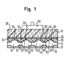
- the device for recognizing a vehicle seat occupancy shown in FIG. 1 has a cushion layer 10 serving as a seat cushion for the vehicle seat.
- the cushion layer 10 is formed from a foam material which is of such strength that, on the one hand, maximum seating comfort and, on the other hand, maximum seating stability is achieved.
- the cushion layer 10 is carried by a seat pan 12, which is arranged below the cushion layer 10.
- a flexible sensor mat 14 filled with a fluid is arranged between the cushion layer 10 and the seat pan 12.
- the sensor mat 14 has a plurality of bubble-like or spherical fluid cells 16. Adjacent fluid cells 16 are each connected to one another by a fluid channel 18. A surface of the sensor mat 14 which faces the cushion layer 10 consequently has hemispherical elevations 20 which are spaced apart from one another by flat regions 22 which are formed by the fluid channels 18.
- the weight 28 passes over the cushion layer 10 exerted a force on the sensor mat 14, which leads to an increase in pressure of the fluid in the sensor mat 14.
- This pressure increase can be measured by suitable pressure sensors, not shown.
- pA
- the force F can be determined from the area A, via which the force F generated by the weight 28 acts on the sensor mat 14, and from the pressure p of the fluid in the sensor mat 14, and thus an occupancy of the vehicle seat can be recognized.
- an intermediate layer 30 is provided which is inserted between the cushion layer 10 and the sensor mat 14.
- the intermediate layer 30 is formed from a harder material than the cushion layer 10, preferably from a high-density foam material such as polyurethane. The intermediate layer 30 thus has a higher strength than the cushion layer 10.
- An upper side of the intermediate layer 30 facing the cushion layer 10 is adapted to an underside 24 of the cushion layer 10 facing the intermediate layer 30.
- the surfaces of the cushion layer 10 and the intermediate layer 30 facing each other are formed flat.
- the intermediate layer 30 can be fastened to the cushion layer 10, for example, by means of an adhesive or an adhesive film 36.
- the intermediate layer 30 is made as thin as possible in order to cause the smallest possible increase in the overall height of the device and thus to ensure a compact construction of the vehicle seat.
- An underside of the intermediate layer 30 facing the sensor mat 14 is formed in such a way that the intermediate layer 30 lies against the sensor mat 14 essentially over its entire surface.
- the underside of the intermediate layer 30 is complementary to the surface of the sensor mat 14, that is to say it has a matrix of hemispherical depressions 32, adjacent depressions 32 each being separated from one another by a flat web 34.
- the depressions 32 are designed such that they are essentially filled by the hemispherical elevations 20 of the fluid cells, while the flat webs 34 adjoin the flat regions 22 of the fluid channels 18. Gaps or air chambers between the sensor mat 14 and the intermediate layer 30 are thus largely excluded.
- the force is transmitted to the sensor mat 14 via the intermediate layer 30. Since the intermediate layer 30 is comparatively stiff, the force is distributed over the entire base area of the intermediate layer 30. At the same time, the intermediate layer 30 is made of such a solid material that it does not deform when force is applied, in particular in the area in which it touches the sensor mat 14 is applied. As a result, the contact area over which the intermediate layer 30 and the sensor mat 14 are in contact with one another is always constant. Hence the area A is also used for the calculation the acting force F from the increase in pressure of the fluid inside the sensor mat 14 is always constant. Regardless of the aging or compression of the foam material or varying moisture in the foam material of the cushion layer 10, reliable detection of seat occupancy is thus permanently ensured.
Landscapes
- Engineering & Computer Science (AREA)
- Mechanical Engineering (AREA)
- Aviation & Aerospace Engineering (AREA)
- Transportation (AREA)
- Physics & Mathematics (AREA)
- Theoretical Computer Science (AREA)
- Mathematical Physics (AREA)
- General Physics & Mathematics (AREA)
- Seats For Vehicles (AREA)
- Mattresses And Other Support Structures For Chairs And Beds (AREA)
- Air Bags (AREA)
- Toilet Supplies (AREA)
- Heating, Cooling, Or Curing Plastics Or The Like In General (AREA)
- Input From Keyboards Or The Like (AREA)
Abstract
Description
- Die Erfindung betrifft eine Vorrichtung zur Erkennung der Belegung eines Sitzes, insbesondere eines Kraftfahrzeugsitzes, mit wenigstens einer als Sitzpolster dienenden Polsterschicht und einer darunter angeordneten Sensorschicht, durch die eine bei Belegung des Sitzes auf die Polsterschicht wirkende Kraft detektierbar ist.
- Grundsätzlich sind derartige Vorrichtungen bekannt. Beispielsweise kann die Sensorschicht eine mit einem Fluid gefüllte Sensormatte aufweisen, bei der die Erkennung einer Sitzbelegung durch eine Bestimmung der Erhöhung des Fluiddrucks in der Sensormatte bei Beaufschlagung der Polsterschicht mit einem Gewicht erfolgt. Für den gemessenen Druck gilt p = |F |/A = m |g |/A, wobei F die durch das Gewicht ausgeübte Kraft ist, das heißt das Produkt aus der Masse m des Gewichts und der Erdbeschleunigung g, und wobei A die Fläche ist, über welche die Kraft auf die Sensormatte ausgeübt wird, dass heißt die Kontaktfläche zwischen Polsterschicht und Sensormatte.
- Problematisch ist bei bekannten Vorrichtungen, dass sich die Kontaktfläche A aufgrund einer Verformung der Polsterschicht an der zur Sensorschicht weisenden Seite im Laufe der Zeit vergrößert, wodurch ein zunehmend reduzierter Fluiddruck p in der Sensormatte ermittelt wird. Insbesondere eine länger andauernde oder häufige Sitzbelegung resultiert somit in einer fehlerhaften Erkennung der Sitzbelegung. Die Veränderung der Kontaktfläche A ist dabei abhängig von Faktoren, die nur schwer zu messen und zu kompensieren sind, wie beispielsweise altersbedingte Kompression oder Härteveränderung der Polsterschicht oder Feuchtigkeit in der Polsterschicht.
- Der Erfindung liegt die Aufgabe zugrunde, eine Vorrichtung der eingangs genannten Art zu schaffen, die eine dauerhaft zuverlässige Erkennung einer Sitzbelegung ermöglicht.
- Zur Lösung der Aufgabe ist eine Vorrichtung mit den Merkmalen des Anspruchs 1 vorgesehen.
- Die erfindungsgemäße Vorrichtung zeichnet sich insbesondere dadurch aus, dass eine Zwischenschicht zwischen der Polsterschicht und der Sensorschicht angeordnet ist. Durch die Zwischenschicht wird ein definierter Grenzbereich zwischen der Polsterschicht und der Sensormatte geschaffen, der es ermöglicht, dass die Polsterschicht und die Sensormatte über eine dauerhaft gleichbleibende Kontaktfläche miteinander in Wechselwirkung stehen. Auf diese Weise kann die Kontaktfläche A auch bei einer länger andauernden Sitzbelegung konstant gehalten werden. Dies ermöglicht eine von dem Alter der Polsterschicht, d.h. der Härte des Schaummaterials, von der Schaumkompression und von der Feuchtigkeit im Schaummaterial unabhängige Erkennung der Sitzbelegung. Somit kann eine Sitzbelegung jederzeit und insbesondere bei einer länger andauernden Belegung des Sitzes im Wesentlichen fehlerfrei erkannt werden.
- Vorteilhafte Ausführungsformen sind den Unteransprüchen, der Beschreibung und der Zeichnung zu entnehmen.
- So ist die Zwischenschicht bei einer vorteilhaften Ausbildung der Erfindung aus einem härteren Material als die Polsterschicht gebildet. Dadurch ist sichergestellt, dass sich die Zwischenschicht nicht wesentlich verformt, wenn die Polsterschicht bei einer Sitzbelegung auf die Zwischenschicht einwirkt. Dies trägt zum Erhalt des definierten Kontaktbereichs zwischen Polsterschicht und Sensorschicht bei, wodurch Fehler bei der Erkennung einer Sitzbelegung vermieden werden.
- Nach einer weiteren Ausführungsform ist die Zwischenschicht aus einem hochdichten Schaummaterial und insbesondere aus einem Hartschaum gebildet. Eine derartige Zwischenschicht ist fester als die Polsterschicht und lässt sich dadurch nicht wesentlich durch die Polsterschicht verformen. Eine Veränderung des Kontaktbereichs zwischen Polsterschicht und Sensorschicht ist somit im Wesentlichen ausgeschlossen.
- Die Zwischenschicht kann aus Polyurethan gebildet sein. Dieses Material ist wegen seiner hohen Festigkeit besonders gut für die Zwischenschicht geeignet und lässt sich darüber hinaus mit geringem wirtschaftlichem Aufwand herstellen und verarbeiten.
- Die Zwischenschicht kann im Wesentlichen über ihre gesamte Fläche hinweg an der Sensorschicht anliegen. Auf diese Weise ist eine dauerhaft gleichbleibende Kontaktfläche zwischen Zwischenschicht und Sensorschicht und dadurch eine dauerhaft zuverlässige Erkennung einer Sitzbelegung gewährleistet.
- Vorteilhafterweise ist eine an die Sensorschicht angrenzende Oberfläche der Zwischenschicht an eine zur Zwischenschicht weisende Oberfläche der Sensorschicht angepasst und insbesondere komplementär zu der Kontur der zur Zwischenschicht weisenden Oberfläche der Sensorschicht ausgebildet. Dadurch wird erreicht, dass die Zwischenschicht insbesondere im Falle einer unebenen Oberflächenkontur der Sensorschicht überall an der Sensorschicht anliegt. Luftkammern zwischen der Sensorschicht und der Zwischenschicht sind dadurch im Wesentlichen ausgeschlossen. Die Zuverlässigkeit der Erkennung einer Sitzbelegung wird somit weiter erhöht.
- Die an die Polsterschicht angrenzende Oberfläche der Zwischenschicht kann an die zur Zwischenschicht weisende Oberfläche der Polsterschicht angepasst und insbesondere plan sein. Dadurch ist eine bei Belegung des Sitzes auf die Polsterschicht wirkende Kraft besonders gleichmäßig auf die Zwischenschicht und somit auf die Sensorschicht übertragbar und das Ergebnis der Erkennung der Sitzbelegung wird weiter verbessert. Im Falle planer Oberflächen ist außerdem die Herstellung der Polsterschicht bzw. der Zwischenschicht vereinfacht.
- Vorzugsweise weist die Sensorschicht eine mit einem Fluid gefüllte Sensormatte auf. Eine derartige Sensormatte stellt ein einfaches Mittel zur Bestimmung einer auf die Polsterschicht wirkenden Kraft dar. Die Sensormatte lässt sich gut in einen Fahrzeugsitz integrieren und weist darüber hinaus eine geringe Bauhöhe auf.
- Nachfolgend wird die Erfindung rein beispielhaft anhand einer vorteilhaften Ausführungsform und unter Bezugnahme auf die beigefügte Zeichnung beschrieben. Es zeigt:
- Fig. 1
- einen schematischen Querschnitt durch eine vorteilhafte Ausführungsform einer erfindungsgemäßen Vorrichtung zur Erkennung einer Sitzbelegung.
- Die in Fig. 1 dargestellte Vorrichtung zur Erkennung einer Kraftfahrzeugsitzbelegung weist eine als Sitzpolster für den Fahrzeugsitz dienende Polsterschicht 10 auf. Die Polsterschicht 10 ist aus einem Schaummaterial gebildet, das eine derartige Festigkeit besitzt, dass einerseits ein maximaler Sitzkomfort und andererseits eine maximale Sitzstabilität erreicht wird.
- Die Polsterschicht 10 ist von einer Sitzpfanne 12 getragen, die unterhalb der Polsterschicht 10 angeordnet ist. Zwischen der Polsterschicht 10 und der Sitzpfanne 12 ist eine flexible und mit einem Fluid gefüllte Sensormatte 14 angeordnet. Die Sensormatte 14 weist eine Vielzahl von blasen- oder kugelartigen Fluidzellen 16 auf. Benachbarte Fluidzellen 16 sind jeweils durch einen Fluidkanal 18 miteinander verbunden. Eine zur Polsterschicht 10 weisende Oberfläche der Sensormatte 14 weist folglich halbkugelartige Erhebungen 20 auf, die durch ebene Bereiche 22, die durch die Fluidkanäle 18 gebildet sind, voneinander beabstandet sind.
- Findet eine Belegung des Fahrzeugsitzes statt, wie es schematisch durch ein auf einer Oberseite 26 der Polsterschicht 10 angeordnetes Gewicht 28 dargestellt ist, so wird durch das Gewicht 28 über die Polsterschicht 10 eine Kraft auf die Sensormatte 14 ausgeübt, die zu einer Druckerhöhung des Fluids in der Sensormatte 14 führt. Diese Druckerhöhung ist durch geeignete, nicht gezeigte Drucksensoren messbar. Gemäß der Gleichung

- Um eine definierte und dauerhaft gleich bleibende Fläche A zu schaffen, über die sich bei einer Sitzbelegung die Kraft F auf die Sensormatte 14 verteilt, ist eine Zwischenschicht 30 vorgesehen, die zwischen die Polsterschicht 10 und die Sensormatte 14 eingefügt ist. Die Zwischenschicht 30 ist aus einem härteren Material als die Polsterschicht 10 gebildet, vorzugsweise aus einem hochdichten Schaummaterial, wie beispielsweise Polyurethan. Die Zwischenschicht 30 weist also eine höhere Festigkeit als die Polsterschicht 10 auf.
- Eine zur Polsterschicht 10 weisende Oberseite der Zwischenschicht 30 ist an eine zur Zwischenschicht 30 weisende Unterseite 24 der Polsterschicht 10 angepasst. Im dargestellten Ausführungsbeispiel sind die jeweils zueinander weisenden Oberflächen der Polsterschicht 10 und der Zwischenschicht 30 plan ausgebildet. Die Zwischenschicht 30 kann beispielsweise mittels eines Klebstoffs oder einer Klebefolie 36 an der Polsterschicht 10 befestigt sein.
- Die Zwischenschicht 30 ist möglichst dünn ausgebildet, um eine möglichst geringe Erhöhung der Bauhöhe der Vorrichtung zu verursachen und somit eine kompakte Bauweise des Fahrzeugsitzes sicherzustellen.
- Eine zur Sensormatte 14 weisende Unterseite der Zwischenschicht 30 ist derart ausgebildet, dass die Zwischenschicht 30 im Wesentlichen über ihre gesamte Fläche hinweg an der Sensormatte 14 anliegt. Zu diesem Zweck ist die Unterseite der Zwischenschicht 30 komplementär zu der Oberfläche der Sensormatte 14 ausgebildet, das heißt sie weist eine Matrix von halbkugelförmigen Vertiefungen 32 auf, wobei benachbarte Vertiefungen 32 jeweils durch einen ebenen Steg 34 voneinander getrennt sind. Die Vertiefungen 32 sind derart ausgebildet, dass sie durch die halbkugelartigen Erhebungen 20 der Fluidzellen im Wesentlichen ausgefüllt werden, während die ebenen Stege 34 an die ebenen Bereiche 22 der Fluidkanäle 18 angrenzen. Zwischenräume oder Luftkammern zwischen der Sensormatte 14 und der Zwischenschicht 30 sind somit weitgehend ausgeschlossen.
- Wird bei einer Belegung des Fahrzeugsitzes durch das Gewicht 28 eine Kraft auf die Polsterschicht 10 ausgeübt, so wird die Kraft über die Zwischenschicht 30 auf die Sensormatte 14 übertragen. Da die Zwischenschicht 30 vergleichsweise steif ist, verteilt sich die Kraft über die gesamte Grundfläche der Zwischenschicht 30. Gleichzeitig besteht die Zwischenschicht 30 aus einem derart festen Material, dass sie sich bei Krafteinwirkung insbesondere in dem Bereich nicht verformt, in dem sie an der Sensormatte 14 anliegt. Dadurch ist die Kontaktfläche, über welche die Zwischenschicht 30 und die Sensormatte 14 miteinander in Berührung stehen, stets konstant. Folglich ist auch die Fläche A, die zur Berechnung der einwirkenden Kraft F aus der Druckerhöhung des Fluids im Inneren der Sensormatte 14 zugrunde gelegt wird, stets konstant. Unabhängig von der Alterung oder Kompression des Schaummaterials oder variierender Feuchtigkeit in dem Schaummaterial der Polsterschicht 10 ist somit dauerhaft eine zuverlässige Erkennung einer Sitzbelegung gewährleistet.
-
- 10
- Polsterschicht
- 12
- Sitzpfanne
- 14
- Sensormatte
- 16
- Fluidzelle
- 18
- Fluidkanal
- 20
- Erhebung
- 22
- ebener Bereich
- 24
- Unterseite
- 26
- Oberseite
- 28
- Gewicht
- 30
- Zwischenschicht
- 32
- Vertiefung
- 34
- ebener Steg
- 36
- Klebefolie
Claims (11)
- Vorrichtung zur Erkennung der Belegung eines Sitzes, insbesondere eines Kraftfahrzeugsitzes, mit wenigstens einer als Sitzpolster dienenden Polsterschicht (10) und einer darunter angeordneten Sensorschicht (14), durch die eine bei Belegung des Sitzes auf die Polsterschicht (10) wirkende Kraft detektierbar ist,
gekennzeichnet durch
eine Zwischenschicht (30), die zwischen der Polsterschicht und der Sensorschicht angeordnet ist. - Vorrichtung nach Anspruch 1,
dadurch gekennzeichnet,
dass die Zwischenschicht (30) aus einem härteren Material als die Polsterschicht gebildet ist. - Vorrichtung nach Anspruch 1 oder 2,
dadurch gekennzeichnet,
dass die Zwischenschicht (30) aus einem hochdichten Schaummaterial und insbesondere aus einem Hartschaum gebildet ist. - Vorrichtung nach einem der vorherigen Ansprüche,
dadurch gekennzeichnet,
dass die Zwischenschicht (30) aus Polyurethan (PUR) gebildet ist. - Vorrichtung nach einem der vorherigen Ansprüche,
dadurch gekennzeichnet,
dass die Zwischenschicht (30) im wesentlichen über ihre gesamte Fläche hinweg an der Sensorschicht (14) anliegt. - Vorrichtung nach einem der vorherigen Ansprüche,
dadurch gekennzeichnet,
dass eine an die Sensorschicht (14) angrenzende Oberfläche der Zwischenschicht (30) an eine zur Zwischenschicht (30) weisende Oberfläche der Sensorschicht (14) angepasst und insbesondere komplementär zu der Kontur der zur Zwischenschicht (30) weisenden Oberfläche der Sensorschicht (14) ausgebildet ist. - Vorrichtung nach einem der vorherigen Ansprüche,
dadurch gekennzeichnet,
dass die an die Polsterschicht (10) angrenzende Oberfläche der Zwischenschicht (30) an die zur Zwischenschicht (30) weisende Oberfläche (24) der Polsterschicht (10) angepasst ist und insbesondere plan ist. - Vorrichtung nach einem der vorherigen Ansprüche,
dadurch gekennzeichnet,
dass die Sensorschicht (14) eine mit einem Fluid gefüllte Sensormatte aufweist. - Vorrichtung nach Anspruch 8,
dadurch gekennzeichnet,
dass die Sensormatte (14) eine Vielzahl von, insbesondere in einer Ebene angeordneten, blasenartigen Fluidzellen (16) aufweist, wobei zueinander benachbarte Fluidzellen (16) jeweils durch einen Fluidkanal (18) miteinander verbunden sind. - Vorrichtung nach einem der vorherigen Ansprüche,
dadurch gekennzeichnet,
dass die Sensorschicht (14) zwischen einer Sitzpfanne (12) und der Zwischenschicht (30) angeordnet ist. - Vorrichtung nach einem der vorherigen Ansprüche,
dadurch gekennzeichnet,
dass die Zwischenschicht (30) fest mit der Polsterschicht (10) verbunden und insbesondere verklebt ist.
Applications Claiming Priority (2)
| Application Number | Priority Date | Filing Date | Title |
|---|---|---|---|
| DE10249871A DE10249871A1 (de) | 2002-10-25 | 2002-10-25 | Vorrichtung zur Erkennung einer Sitzbelegung |
| DE10249871 | 2002-10-25 |
Publications (2)
| Publication Number | Publication Date |
|---|---|
| EP1413863A1 true EP1413863A1 (de) | 2004-04-28 |
| EP1413863B1 EP1413863B1 (de) | 2006-01-11 |
Family
ID=32049616
Family Applications (1)
| Application Number | Title | Priority Date | Filing Date |
|---|---|---|---|
| EP03023680A Expired - Lifetime EP1413863B1 (de) | 2002-10-25 | 2003-10-17 | Erkennen einer Sitzbelegung ohne Alterung mit einem Blasenwandler durch eine Zwischenschicht |
Country Status (3)
| Country | Link |
|---|---|
| EP (1) | EP1413863B1 (de) |
| AT (1) | ATE315776T1 (de) |
| DE (2) | DE10249871A1 (de) |
Cited By (1)
| Publication number | Priority date | Publication date | Assignee | Title |
|---|---|---|---|---|
| EP2492137A3 (de) * | 2011-02-24 | 2014-02-26 | I.G. Bauerhin GmbH | Belegungserfassungseinrichtung zum Detektieren des Belegungszustandes eines Kraftfahrzeugsitzes |
Families Citing this family (6)
| Publication number | Priority date | Publication date | Assignee | Title |
|---|---|---|---|---|
| US20050184496A1 (en) | 2003-10-03 | 2005-08-25 | Speckhart Frank H. | Sensor pad for controlling airbag deployment and associated support |
| DE202004019805U1 (de) | 2004-12-23 | 2005-06-23 | Robert Bosch Gmbh | Sensormatte |
| DE102005056882B4 (de) | 2005-01-24 | 2012-06-14 | F.S. Fehrer Automotive Gmbh | Kraftfahrzeugsitz mit Insassendetektor |
| DE102010033624A1 (de) | 2010-08-06 | 2012-02-09 | Daimler Ag | Sitzplatzbelegungserkennungssystem für ein Kraftfahrzeug |
| DE102011012367C5 (de) * | 2011-02-24 | 2019-04-04 | I.G. Bauerhin Gmbh | Belegungserfassungseinrichtung zum Detektieren des Belegungszustandes eines Kraftfahrzeugsitzes |
| US10137802B2 (en) | 2016-03-11 | 2018-11-27 | Ford Global Technologies, Llc | Detecting occupant presence on a vehicle seat |
Citations (6)
| Publication number | Priority date | Publication date | Assignee | Title |
|---|---|---|---|---|
| US5176424A (en) * | 1988-06-10 | 1993-01-05 | Mazda Motor Corporation | Automobile seat assembly |
| US5918696A (en) * | 1997-09-05 | 1999-07-06 | Automotive Systems Laboratory, Inc. | Seat weight sensor with means for distributing loads |
| US5957491A (en) * | 1996-12-19 | 1999-09-28 | Automotive Systems Laboratory, Inc. | Seat weight sensor having fluid filled bladder |
| US5979585A (en) * | 1997-09-05 | 1999-11-09 | Automotive Systems Laboratory, Inc. | Seat weight sensor having self-regulating fluid filled bladder |
| US6392166B1 (en) * | 2000-01-28 | 2002-05-21 | Delphi Technologies, Inc. | Stress relief method for a fluid filled elastomeric bladder |
| EP1245433A2 (de) * | 2001-03-26 | 2002-10-02 | Delphi Technologies, Inc. | Sitzinsassengewichtsdetektionssystem mit Kompensation von Alterung und Verwendung des Sitzes |
Family Cites Families (6)
| Publication number | Priority date | Publication date | Assignee | Title |
|---|---|---|---|---|
| IT1224463B (it) * | 1988-10-03 | 1990-10-04 | Fiat Auto Spa | Sedile a struttura strattificata particolarmente per autoveicoli |
| JP3728711B2 (ja) * | 1996-11-29 | 2005-12-21 | アイシン精機株式会社 | 着座検出装置 |
| DE19845730B4 (de) * | 1998-10-05 | 2005-02-10 | Audi Ag | Polsterträger |
| DE19938698A1 (de) * | 1999-08-14 | 2001-02-15 | Volkswagen Ag | Fahrzeugsitz |
| JP2001080404A (ja) * | 1999-09-17 | 2001-03-27 | Aisin Seiki Co Ltd | 着座検知装置 |
| DE20014200U1 (de) * | 2000-08-17 | 2000-12-14 | Siemens AG, 80333 München | Sensoranordnung |
-
2002
- 2002-10-25 DE DE10249871A patent/DE10249871A1/de not_active Withdrawn
-
2003
- 2003-10-17 AT AT03023680T patent/ATE315776T1/de not_active IP Right Cessation
- 2003-10-17 DE DE50302168T patent/DE50302168D1/de not_active Expired - Lifetime
- 2003-10-17 EP EP03023680A patent/EP1413863B1/de not_active Expired - Lifetime
Patent Citations (6)
| Publication number | Priority date | Publication date | Assignee | Title |
|---|---|---|---|---|
| US5176424A (en) * | 1988-06-10 | 1993-01-05 | Mazda Motor Corporation | Automobile seat assembly |
| US5957491A (en) * | 1996-12-19 | 1999-09-28 | Automotive Systems Laboratory, Inc. | Seat weight sensor having fluid filled bladder |
| US5918696A (en) * | 1997-09-05 | 1999-07-06 | Automotive Systems Laboratory, Inc. | Seat weight sensor with means for distributing loads |
| US5979585A (en) * | 1997-09-05 | 1999-11-09 | Automotive Systems Laboratory, Inc. | Seat weight sensor having self-regulating fluid filled bladder |
| US6392166B1 (en) * | 2000-01-28 | 2002-05-21 | Delphi Technologies, Inc. | Stress relief method for a fluid filled elastomeric bladder |
| EP1245433A2 (de) * | 2001-03-26 | 2002-10-02 | Delphi Technologies, Inc. | Sitzinsassengewichtsdetektionssystem mit Kompensation von Alterung und Verwendung des Sitzes |
Cited By (2)
| Publication number | Priority date | Publication date | Assignee | Title |
|---|---|---|---|---|
| EP2492137A3 (de) * | 2011-02-24 | 2014-02-26 | I.G. Bauerhin GmbH | Belegungserfassungseinrichtung zum Detektieren des Belegungszustandes eines Kraftfahrzeugsitzes |
| DE102012003243B4 (de) * | 2011-02-24 | 2020-09-17 | I.G. Bauerhin Gmbh | Belegungserfassungseinrichtung zum Detektieren eines Belegungszustandes eines Kraftfahrzeugsitzes |
Also Published As
| Publication number | Publication date |
|---|---|
| ATE315776T1 (de) | 2006-02-15 |
| DE10249871A1 (de) | 2004-05-06 |
| DE50302168D1 (de) | 2006-04-06 |
| EP1413863B1 (de) | 2006-01-11 |
Similar Documents
| Publication | Publication Date | Title |
|---|---|---|
| EP0705549B1 (de) | Hohlkörper für die Benutzung als Sitzunterlage | |
| EP2406102B1 (de) | Fahrzeugsitzpolster | |
| DE112013005102B4 (de) | Sitzbelegungssensoreinheit zum Erkennen eines Belegungszustands eines Sitzes und Fahrzeugsitz mit einer solchen Sitzbelegungssensoreinheit | |
| EP4119742B1 (de) | Entkopplungsmatte | |
| DE60006727T2 (de) | Fahrradsattel | |
| EP2492137B1 (de) | Belegungserfassungseinrichtung zum Detektieren des Belegungszustandes eines Kraftfahrzeugsitzes | |
| EP1413863B1 (de) | Erkennen einer Sitzbelegung ohne Alterung mit einem Blasenwandler durch eine Zwischenschicht | |
| DE102006006780B4 (de) | Kollisionsfeststellungssensor für Fahrzeuge und diesen benutzende Vorrichtung zur Beurteilung von Hindernissen | |
| EP1427611B1 (de) | Vorrichtung zur gewichtsklassifizierung von personen | |
| EP1053455A1 (de) | Drucksensibler flächensensor | |
| CH658129A5 (de) | Vorrichtung zum messen einer kraft. | |
| EP0541884B1 (de) | Gleisoberbau mit Zwischenplatte | |
| DE3738762A1 (de) | Antirutscheinrichtung an einer abstellflaeche | |
| DE102011012367B4 (de) | Belegungserfassungseinrichtung zum Detektieren des Belegungszustandes eines Kraftfahrzeugsitzes | |
| DE102005056882B4 (de) | Kraftfahrzeugsitz mit Insassendetektor | |
| DE10353596A1 (de) | Sitz | |
| AT395254B (de) | Gleisoberbau mit zwischenplatte | |
| EP1067012A3 (de) | Sitzelement, insbesondere ein Kraftfahrzeugsitz mit Belastungserkennungsvorrichtung | |
| AT389171B (de) | Vorrichtung zum messen von belastungen in verbundkoerpern | |
| CH719125B1 (de) | Raumverkleidungselement | |
| DE102017116137B4 (de) | Kontinuierliche Profiltiefenerkennung bei Fahrzeugreifen | |
| DE29720363U1 (de) | Anordnung zur Gewichtserkennung, insbesondere für Systeme zur Erkennung der Sitzbelegung | |
| DE10028462A1 (de) | Bodendämmung für Fahrzeuge und Fahrzeugbodenaufbau mit einer derartigen Bodendämmung | |
| EP0726449B1 (de) | Tragbare Messvorrichtung zur Gewichtsbestimmung von Fahrzeugen | |
| DE29717506U1 (de) | Montageeinrichtung |
Legal Events
| Date | Code | Title | Description |
|---|---|---|---|
| PUAI | Public reference made under article 153(3) epc to a published international application that has entered the european phase |
Free format text: ORIGINAL CODE: 0009012 |
|
| AK | Designated contracting states |
Kind code of ref document: A1 Designated state(s): AT BE BG CH CY CZ DE DK EE ES FI FR GB GR HU IE IT LI LU MC NL PT RO SE SI SK TR |
|
| AX | Request for extension of the european patent |
Extension state: AL LT LV MK |
|
| 17P | Request for examination filed |
Effective date: 20040622 |
|
| AKX | Designation fees paid |
Designated state(s): AT BE BG CH CY CZ DE DK EE ES FI FR GB GR HU IE IT LI LU MC NL PT RO SE SI SK TR |
|
| 17Q | First examination report despatched |
Effective date: 20041227 |
|
| GRAP | Despatch of communication of intention to grant a patent |
Free format text: ORIGINAL CODE: EPIDOSNIGR1 |
|
| GRAS | Grant fee paid |
Free format text: ORIGINAL CODE: EPIDOSNIGR3 |
|
| GRAA | (expected) grant |
Free format text: ORIGINAL CODE: 0009210 |
|
| AK | Designated contracting states |
Kind code of ref document: B1 Designated state(s): AT BE BG CH CY CZ DE DK EE ES FI FR GB GR HU IE IT LI LU MC NL PT RO SE SI SK TR |
|
| PG25 | Lapsed in a contracting state [announced via postgrant information from national office to epo] |
Ref country code: NL Free format text: LAPSE BECAUSE OF FAILURE TO SUBMIT A TRANSLATION OF THE DESCRIPTION OR TO PAY THE FEE WITHIN THE PRESCRIBED TIME-LIMIT Effective date: 20060111 Ref country code: RO Free format text: LAPSE BECAUSE OF FAILURE TO SUBMIT A TRANSLATION OF THE DESCRIPTION OR TO PAY THE FEE WITHIN THE PRESCRIBED TIME-LIMIT Effective date: 20060111 Ref country code: IE Free format text: LAPSE BECAUSE OF FAILURE TO SUBMIT A TRANSLATION OF THE DESCRIPTION OR TO PAY THE FEE WITHIN THE PRESCRIBED TIME-LIMIT Effective date: 20060111 Ref country code: SI Free format text: LAPSE BECAUSE OF FAILURE TO SUBMIT A TRANSLATION OF THE DESCRIPTION OR TO PAY THE FEE WITHIN THE PRESCRIBED TIME-LIMIT Effective date: 20060111 Ref country code: FI Free format text: LAPSE BECAUSE OF FAILURE TO SUBMIT A TRANSLATION OF THE DESCRIPTION OR TO PAY THE FEE WITHIN THE PRESCRIBED TIME-LIMIT Effective date: 20060111 Ref country code: SK Free format text: LAPSE BECAUSE OF FAILURE TO SUBMIT A TRANSLATION OF THE DESCRIPTION OR TO PAY THE FEE WITHIN THE PRESCRIBED TIME-LIMIT Effective date: 20060111 |
|
| REG | Reference to a national code |
Ref country code: CH Ref legal event code: EP |
|
| GBT | Gb: translation of ep patent filed (gb section 77(6)(a)/1977) |
Effective date: 20060111 |
|
| REG | Reference to a national code |
Ref country code: IE Ref legal event code: FG4D Free format text: LANGUAGE OF EP DOCUMENT: GERMAN |
|
| REF | Corresponds to: |
Ref document number: 50302168 Country of ref document: DE Date of ref document: 20060406 Kind code of ref document: P |
|
| PG25 | Lapsed in a contracting state [announced via postgrant information from national office to epo] |
Ref country code: DK Free format text: LAPSE BECAUSE OF FAILURE TO SUBMIT A TRANSLATION OF THE DESCRIPTION OR TO PAY THE FEE WITHIN THE PRESCRIBED TIME-LIMIT Effective date: 20060411 Ref country code: BG Free format text: LAPSE BECAUSE OF FAILURE TO SUBMIT A TRANSLATION OF THE DESCRIPTION OR TO PAY THE FEE WITHIN THE PRESCRIBED TIME-LIMIT Effective date: 20060411 Ref country code: SE Free format text: LAPSE BECAUSE OF FAILURE TO SUBMIT A TRANSLATION OF THE DESCRIPTION OR TO PAY THE FEE WITHIN THE PRESCRIBED TIME-LIMIT Effective date: 20060411 |
|
| PG25 | Lapsed in a contracting state [announced via postgrant information from national office to epo] |
Ref country code: ES Free format text: LAPSE BECAUSE OF FAILURE TO SUBMIT A TRANSLATION OF THE DESCRIPTION OR TO PAY THE FEE WITHIN THE PRESCRIBED TIME-LIMIT Effective date: 20060422 |
|
| PG25 | Lapsed in a contracting state [announced via postgrant information from national office to epo] |
Ref country code: PT Free format text: LAPSE BECAUSE OF FAILURE TO SUBMIT A TRANSLATION OF THE DESCRIPTION OR TO PAY THE FEE WITHIN THE PRESCRIBED TIME-LIMIT Effective date: 20060612 |
|
| NLV1 | Nl: lapsed or annulled due to failure to fulfill the requirements of art. 29p and 29m of the patents act | ||
| ET | Fr: translation filed | ||
| REG | Reference to a national code |
Ref country code: IE Ref legal event code: FD4D |
|
| PG25 | Lapsed in a contracting state [announced via postgrant information from national office to epo] |
Ref country code: MC Free format text: LAPSE BECAUSE OF NON-PAYMENT OF DUE FEES Effective date: 20061031 |
|
| PLBE | No opposition filed within time limit |
Free format text: ORIGINAL CODE: 0009261 |
|
| STAA | Information on the status of an ep patent application or granted ep patent |
Free format text: STATUS: NO OPPOSITION FILED WITHIN TIME LIMIT |
|
| 26N | No opposition filed |
Effective date: 20061012 |
|
| BERE | Be: lapsed |
Owner name: DELPHI TECHNOLOGIES, INC. Effective date: 20061031 |
|
| PG25 | Lapsed in a contracting state [announced via postgrant information from national office to epo] |
Ref country code: AT Free format text: LAPSE BECAUSE OF NON-PAYMENT OF DUE FEES Effective date: 20061017 |
|
| PG25 | Lapsed in a contracting state [announced via postgrant information from national office to epo] |
Ref country code: CZ Free format text: LAPSE BECAUSE OF FAILURE TO SUBMIT A TRANSLATION OF THE DESCRIPTION OR TO PAY THE FEE WITHIN THE PRESCRIBED TIME-LIMIT Effective date: 20060111 Ref country code: GR Free format text: LAPSE BECAUSE OF FAILURE TO SUBMIT A TRANSLATION OF THE DESCRIPTION OR TO PAY THE FEE WITHIN THE PRESCRIBED TIME-LIMIT Effective date: 20060412 |
|
| REG | Reference to a national code |
Ref country code: CH Ref legal event code: PL |
|
| PG25 | Lapsed in a contracting state [announced via postgrant information from national office to epo] |
Ref country code: EE Free format text: LAPSE BECAUSE OF FAILURE TO SUBMIT A TRANSLATION OF THE DESCRIPTION OR TO PAY THE FEE WITHIN THE PRESCRIBED TIME-LIMIT Effective date: 20060111 |
|
| PG25 | Lapsed in a contracting state [announced via postgrant information from national office to epo] |
Ref country code: HU Free format text: LAPSE BECAUSE OF FAILURE TO SUBMIT A TRANSLATION OF THE DESCRIPTION OR TO PAY THE FEE WITHIN THE PRESCRIBED TIME-LIMIT Effective date: 20060712 Ref country code: TR Free format text: LAPSE BECAUSE OF FAILURE TO SUBMIT A TRANSLATION OF THE DESCRIPTION OR TO PAY THE FEE WITHIN THE PRESCRIBED TIME-LIMIT Effective date: 20060111 Ref country code: CH Free format text: LAPSE BECAUSE OF NON-PAYMENT OF DUE FEES Effective date: 20071031 Ref country code: LU Free format text: LAPSE BECAUSE OF NON-PAYMENT OF DUE FEES Effective date: 20061017 Ref country code: LI Free format text: LAPSE BECAUSE OF NON-PAYMENT OF DUE FEES Effective date: 20071031 |
|
| PG25 | Lapsed in a contracting state [announced via postgrant information from national office to epo] |
Ref country code: CY Free format text: LAPSE BECAUSE OF FAILURE TO SUBMIT A TRANSLATION OF THE DESCRIPTION OR TO PAY THE FEE WITHIN THE PRESCRIBED TIME-LIMIT Effective date: 20060111 |
|
| PG25 | Lapsed in a contracting state [announced via postgrant information from national office to epo] |
Ref country code: BE Free format text: LAPSE BECAUSE OF FAILURE TO SUBMIT A TRANSLATION OF THE DESCRIPTION OR TO PAY THE FEE WITHIN THE PRESCRIBED TIME-LIMIT Effective date: 20061031 |
|
| PGFP | Annual fee paid to national office [announced via postgrant information from national office to epo] |
Ref country code: DE Payment date: 20091015 Year of fee payment: 7 |
|
| PGFP | Annual fee paid to national office [announced via postgrant information from national office to epo] |
Ref country code: FR Payment date: 20091029 Year of fee payment: 7 Ref country code: GB Payment date: 20091014 Year of fee payment: 7 Ref country code: IT Payment date: 20091017 Year of fee payment: 7 |
|
| GBPC | Gb: european patent ceased through non-payment of renewal fee |
Effective date: 20101017 |
|
| PG25 | Lapsed in a contracting state [announced via postgrant information from national office to epo] |
Ref country code: FR Free format text: LAPSE BECAUSE OF NON-PAYMENT OF DUE FEES Effective date: 20101102 |
|
| REG | Reference to a national code |
Ref country code: FR Ref legal event code: ST Effective date: 20110630 |
|
| PG25 | Lapsed in a contracting state [announced via postgrant information from national office to epo] |
Ref country code: GB Free format text: LAPSE BECAUSE OF NON-PAYMENT OF DUE FEES Effective date: 20101017 |
|
| REG | Reference to a national code |
Ref country code: DE Ref legal event code: R119 Ref document number: 50302168 Country of ref document: DE Effective date: 20110502 |
|
| PG25 | Lapsed in a contracting state [announced via postgrant information from national office to epo] |
Ref country code: IT Free format text: LAPSE BECAUSE OF NON-PAYMENT OF DUE FEES Effective date: 20101017 |
|
| PG25 | Lapsed in a contracting state [announced via postgrant information from national office to epo] |
Ref country code: DE Free format text: LAPSE BECAUSE OF NON-PAYMENT OF DUE FEES Effective date: 20110502 |